Lapsed, fee not paid5 drawings
Hardware & Electronics · US 9,756,168 B1
Multifunction mobile devices and appliance control
A wireless communication and control system including a wireless device.
US 9,756,172 B2 · Assignee: Apple Inc. · Inventors: Piemonte; Patrick S. et al.
Sheet 1 of 14 from the published document. All sheets in the USPTO PDF
Methods and apparatus for an environment analysis tool on a mobile device which may construct a model of the surrounding environment in order to determine whether or not characteristics of the model implicate a degradation in wireless signal quality. In response to an analysis of the constructed model to determine signal quality, the environment analysis tool may alter the behavior of any number of hardware or software functions to avoid or reduce efforts to receive or use the affected signal over the duration of the mobile device's presence within the environment with the signal-degrading characteristics.
The performance of various software or hardware functions on a mobile device may depend on characteristics of the surrounding environment. Specifically, when a mobile device has functionality that depends on wireless communication, the wireless reception and transmission efforts of the mobile device may become less efficient or may become fruitless due to interference with a given wireless signal. For example, areas with a dense amount of tall buildings may be characterized as urban canyons, which may impede, among other signals, GPS signals. In such a case, any attempts by the mobile device to search for a GPS signal while the mobile device is in the urban canyon may be a waste of processing cycles or battery power.
1 of 14 drawing sheets so far from the published document, cropped to the drawing. Every sheet is in the USPTO PDF.
What the patent claimed, word for word. All of it is now free to use.
The performance of various software or hardware functions on a mobile device may depend on characteristics of the surrounding environment. Specifically, when a mobile device has functionality that depends on wireless communication, the wireless reception and transmission efforts of the mobile device may become less efficient or may become fruitless due to interference with a given wireless signal. For example, areas with a dense amount of tall buildings may be characterized as urban canyons, which may impede, among other signals, GPS signals. In such a case, any attempts by the mobile device to search for a GPS signal while the mobile device is in the urban canyon may be a waste of processing cycles or battery power.
In one embodiment, a mobile device may construct a model of the surrounding environment in order to determine whether or not one or more characteristics of the model implicate a degradation in wireless signal quality. In response to an analysis of the constructed model to determine possible effects on signal quality, the mobile device may alter the behavior of any number of hardware or software functions to avoid or reduce efforts to receive or use the affected signal over the duration of the mobile device's presence within the environment with the signal-degrading characteristics.
FIG. 1A is an illustration of a mobile device suitable to implement an environment analysis tool, according to some embodiments.
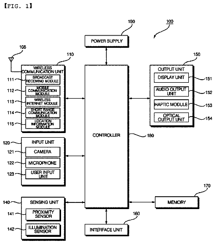
FIG. 1B is a diagram illustrating example components within a mobile device suitable for implementing an environment analysis tool, according to some embodiments.
FIG. 2 illustrates a touch screen on a mobile device, according to some embodiments.
FIG. 3 illustrates another mobile device configurable to implement a mapping application and an environment analysis tool, according to some embodiments.
FIGS. 4A-4E depict example flowcharts corresponding to different embodiments of an environment analysis tool, according to some embodiments.
FIG. 5 depicts an illustration of a model of a surrounding environment, according to some embodiments.
FIG. 6 illustrates an environment analysis tool module, according to some embodiments.
FIG. 7 depicts elements of an example computer system capable of implementing an environment analysis tool.
FIG. 8 depicts an illustration of a cloud computing environment that may be used in some embodiments of the environment analysis tool.
FIG. 9 depicts elements of a map service operating environment, according to some embodiments.
While the invention is described herein by way of example for several embodiments and illustrative drawings, those skilled in the art will recognize that the invention is not limited to the embodiments or drawings described. It should be understood that the drawings and detailed description are not intended to limit the invention to the particular forms disclosed, but on the contrary, the intention is to cover all modifications, equivalents and alternatives falling within the spirit and scope of the present invention. The headings used are for organizational purposes only and are not meant to be used to limit the scope of the description. As used throughout this application, the word “may” is used in a permissive sense (meaning “having the potential to”), rather than the mandatory sense (meaning “must”). Similarly, the words “include”, “including”, and “includes” mean “including, but not limited to.” DETAILED DESCRIPTION OF EMBODIMENTS
Various embodiments are presented of an environment analysis tool on a mobile device which may determine when, how, or for how long the mobile device alters functionality related to signal search or signal use based on the mobile device's presence within an environment which may degrade signal quality used by the mobile device.
In some cases, a mobile device may have access to information regarding the surrounding environment, including structures, terrain, or heat maps depicting signal strength. The information regarding the surrounding environment may be determined from received mapping information, where the mapping information may include information on terrain, and locations, shapes, and dimensions of surrounding objects. The information regarding the surrounding environment may also be determined from heat maps which may provide information on specific locations or areas where a given signal may be poorly received or not at all received.
In some cases, an environment analysis tool on a mobile device, given mapping information for the surrounding environment, may construct a model representing the surrounding environment. The model may be constructed in a variety of ways. From the model, the mobile device may identify heights of surrounding buildings and identify an arrangement of those buildings that may be an urban canyon where various types of signals may be degraded or absent. In response, the environment analysis tool may cause the mobile device to less aggressively use or cease using or searching for a GPS signal until the urban canyon has been exited. In other cases, the environment analysis tool may cause the mobile device to power down the GPS circuitry or transition the GPS circuitry to a low-power state until the urban canyon has been exited. Without GPS data to determine a location, the environment analysis tool may rely on other sensors to determine location and to determine when the urban canyon has been exited. For example, the environment analysis tool may rely on a combination of a compass, gyroscope or accelerometer within the mobile device to determine a location. In other examples, the environment analysis tool may use Wi-Fi hotspots to provide information regarding location. In other example, the environment analysis tool may triangulate a location based on cell phone towers until an urban canyon is exited.
In some cases, the environment analysis tool may adjust hardware or software functionality based on determining a degradation of various types of signals, including GPS, Wi-Fi, or cellular signals. However, the environment analysis tool may equally be applied to adjust hardware or software functionality on other types of mobile device signals that may be affected by characteristics of the surrounding environment.
As noted above, in some cases the environment analysis tool may determine the loss or impending loss of a given signal, and in response cause the mobile device to change the mode or frequency in which the given signal is used or searched for. In some cases, the environment analysis tool, in response to determining the loss or impending loss of a given signal, may instruct the mobile device to use alternate frequencies. In some cases, the environment analysis tool may instruct the mobile device to enter a passive search mode or a low-power mode or to power down the circuitry or components associated with searching for or processing the signal. The affected components on the mobile device may be software components, hardware components, or both.
In some cases, the environment analysis tool may calculate tradeoffs before determining a response. For example, if based on the current user/mobile device trajectory, the environment analysis tool determines that a signal may only be lost or degraded for a few minutes, and that the resulting power savings in changing modes related to using/detecting the degraded signal would be miniscule, the environment analysis tool may elect to not alter any mode settings. In other cases, the environment analysis tool may, based on the length of time in which the mobile device is to be in an area with a degraded signal, determine to enter a low-power mode instead of powering down components corresponding the signal. These environment analysis tool determinations may also be based on the amount of signal degradation that is calculated to be expected. In other words, if the signal degradation is determined to be small, the environment analysis tool may elect to not make any mode or processing changes within the mobile device.
Regarding determinations of impending signal loss or degradation, the environment analysis tool may rely on various methods. As noted above, the environment analysis tool may receive mapping information from which a model of the surrounding environment is constructed. The model may be constructed in multiple ways. For example, the environment analysis tool may use three-dimensional mapping information of a surrounding area in conjunction with two-dimensional information for the surrounding area, where the two-dimensional information includes building footprints and the three-dimensional information includes height information for one or more points within a given building footprint. In this way, the environment analysis tool may construct a quick three-dimensional model of the surrounding environment based on mapping information that includes vector graphics data instead of (or in addition to) raster data.
In other cases, the environment analysis tool may simply use three-dimensional mapping information to construct a three-dimensional model of the surrounding environment. For example, the environment analysis tool may create a two-dimensional representation of a region of the surrounding environment, where the two-dimensional representation is divided into multiple segments. In this example, the environment analysis tool may use three-dimensional mapping information to correlate a height value for an object in the three-dimensional mapping information with each of the segments in the two-dimensional representation of the region. In this way, each of the two-dimensional segments may be modified to include a height value, thereby producing a rough three-dimensional model of the surrounding environment.
In an embodiment, three-dimensional data may be three-dimensional mesh data, which may contain data defining the location and orientation of thousands of triangles for a given map view. Further in this embodiment, two-dimensional data may be obtained from maps for a given city or county which define the locations and the dimensions of footprints for structures, roads, sidewalks, plazas, or other objects. In this embodiment, in the interest of speed and computational complexity, a three-dimensional proxy may be constructed through the transformation of the two-dimensional model into a three-dimensional model using selected pieces of information from the three-dimensional model to enhance the two-dimensional model. For example, if the two-dimensional model provides information regarding the footprint of a given building, the environment analysis tool may then reference the three-dimensional model to identify the corresponding location of the footprint of the building. Once the location of the footprint of the building is determined in the three-dimensional model, one or more height values may be extracted from the three-dimensional model for the building. Now, given the footprint of the building and the one or more height values, a rough box or polygon may be extruded to one of the height values, or to some value derived from the height values in order to generate an approximate three-dimensional shape. This process may be repeated for each object in the two-dimensional data, thereby creating a rough, low-resolution version of the surrounding environment.
Other response to the environment analysis tool determining that a mobile device has entered or is about to enter a region with an absent or degraded signal is to prefetch information that may not be available while the mobile device is in the region of the degraded/absent signal. For example, in some cases, a mobile device may provide a user with a mapping application that may include a navigation view. To generate the navigation view, the mapping application may rely on mapping information received along a signal that is expected to be degraded or absent. In this case, the environment analysis tool may prefetch or request the mapping information that may be needed while the mobile device is within the region of the degraded/absent signal. For example, if the environment analysis tool determines that an urban canyon exists for the next two city blocks, then the environment analysis tool may prefetch or request mapping information in order for a mapping application to provide uninterrupted mapping services while the mobile device is within the urban canyon. Similarly, to prevent an interruption in other mobile device services, the environment analysis tool may prefetch other types of information that may not be available while the mobile device is within a region where a particular signal is degraded or absent.
Detailed Description Considerations
In the following detailed description, numerous details are set forth to provide a thorough understanding of the claimed subject matter. However, it will be understood by those skilled in the art that the claimed subject matter may be practiced without these specific details. In other instances, methods, apparatus or systems that would be known by one of ordinary skill have not been described in detail so as not to obscure claimed subject matter.
It will also be understood that, although the terms first, second, etc. may be used herein to describe various elements, these elements should not be limited by these terms. These terms are only used to distinguish one element from another. For example, a first contact could be termed a second contact, and, similarly, a second contact could be termed a first contact, without departing from the scope of the present invention. The first contact and the second contact are both contacts, but they are not the same contact.
Embodiments of electronic devices, user interfaces for such devices, and associated processes for using such devices are described. In some embodiments, the device is a portable communications device, such as a mobile telephone, that also contains other functions, such as PDA and/or music player functions. Exemplary embodiments of mobile devices include, without limitation, the iPhone®, iPod Touch®, and iPad® devices from Apple Inc. of Cupertino, Calif. Other portable electronic devices, such as laptops or tablet computers with touch-sensitive surfaces (e.g., touch screen displays and/or touch pads), may also be used. It should also be understood that, in some embodiments, the device is not a portable communications device, but is a desktop computer with a touch-sensitive surface (e.g., a touch screen display and/or a touch pad). In some embodiments, the device is a gaming computer with orientation sensors (e.g., orientation sensors in a gaming controller).
In the discussion that follows, an electronic device that includes a display and a touch-sensitive surface is described. It should be understood, however, that the electronic device may include one or more other physical user-interface devices, such as a physical keyboard, a mouse and/or a joystick.
The device typically supports a variety of applications, such as one or more of the following: a drawing application, a presentation application, a word processing application, a website creation application, a disk authoring application, a spreadsheet application, a gaming application, a telephone application, a video conferencing application, an e-mail application, an instant messaging application, a workout support application, a photo management application, a digital camera application, a digital video camera application, a web browsing application, a digital music player application, and/or a digital video player application.
The various applications that may be executed on the device may use at least one common physical user-interface device, such as the touch-sensitive surface. One or more functions of the touch-sensitive surface as well as corresponding information displayed on the device may be adjusted and/or varied from one application to the next and/or within a respective application. In this way, a common physical architecture (such as the touch-sensitive surface) of the device may support the variety of applications with user interfaces that are intuitive and transparent to the user.
Some portions of the detailed description which follow are presented in terms of algorithms or symbolic representations of operations on binary digital signals stored within a memory of a specific apparatus or special purpose computing device or platform. In the context of this particular specification, the term specific apparatus or the like includes a general purpose computer once it is programmed to perform particular functions pursuant to instructions from program software. Algorithmic descriptions or symbolic representations are examples of techniques used by those of ordinary skill in the signal processing or related arts to convey the substance of their work to others skilled in the art. An algorithm is here, and is generally, considered to be a self-consistent sequence of operations or similar signal processing leading to a desired result. In this context, operations or processing involve physical manipulation of physical quantities. Typically, although not necessarily, such quantities may take the form of electrical or magnetic signals capable of being stored, transferred, combined, compared or otherwise manipulated. It has proven convenient at times, principally for reasons of common usage, to refer to such signals as bits, data, values, elements, symbols, characters, terms, numbers, numerals or the like. It should be understood, however, that all of these or similar terms are to be associated with appropriate physical quantities and are merely convenient labels. Unless specifically stated otherwise, as apparent from the following discussion, it is appreciated that throughout this specification discussions utilizing terms such as “processing”, “computing”, “calculating”, “determining”, or the like refer to actions or processes of a specific apparatus, such as a special purpose computer or a similar special purpose electronic computing device. In the context of this specification, therefore, a special purpose computer or a similar special purpose electronic computing device is capable of manipulating or transforming signals, typically represented as physical electronic or magnetic quantities within memories, registers, or other information storage devices, transmission devices, or display devices of the special purpose computer or similar special purpose electronic computing device.
Example Mobile Device
Attention is now directed toward embodiments of portable devices with touch-sensitive displays. FIG. 1A is a block diagram illustrating portable mobile device 100 with touch-sensitive displays 112 in accordance with some embodiments. Touch-sensitive display 112 is sometimes called a “touch screen” for convenience, and may also be known as or called a touch-sensitive display system. Device 100 may include memory 102 (which may include one or more computer-readable storage mediums, including non-transitory computer-readable storage mediums), memory controller 122 , one or more processing units (CPU's) 120 , peripherals interface 118 , RF circuitry 108 , audio circuitry 110 , speaker 111 , microphone 113 , input/output (I/O) subsystem 106 , other input or control devices 116 , and external port 124 . Device 100 may include one or more optical sensors 164 . These components may communicate over one or more communication buses or signal lines 103 .
It should be appreciated that device 100 is only one example of a portable mobile device, and that device 100 may have more or fewer components than shown, may combine two or more components, or may have a different configuration or arrangement of the components. The various components shown in FIG. 1A may be implemented in hardware, software, or a combination of both hardware and software, including one or more signal processing and/or application specific integrated circuits.
Memory 102 may include high-speed random access memory and may also include non-volatile memory, such as one or more magnetic disk storage devices, flash memory devices, or other non-volatile solid-state memory devices. Access to memory 102 by other components of device 100 , such as CPU 120 and the peripherals interface 118 , may be controlled by memory controller 122 .
Peripherals interface 118 can be used to couple input and output peripherals of the device to CPU 120 and memory 102 . The one or more processors 120 run or execute various software programs and/or sets of instructions stored in memory 102 to perform various functions for device 100 and to process data.
In some embodiments, peripherals interface 118 , CPU 120 , and memory controller 122 may be implemented on a single chip, such as chip 104 . In some other embodiments, they may be implemented on separate chips.
RF (radio frequency) circuitry 108 receives and sends RF signals, also called electromagnetic signals. RF circuitry 108 converts electrical signals to/from electromagnetic signals and communicates with communications networks and other communications devices via the electromagnetic signals. RF circuitry 108 may include well-known circuitry for performing these functions, including but not limited to an antenna system, an RF transceiver, one or more amplifiers, a tuner, one or more oscillators, a digital signal processor, a CODEC chipset, a subscriber identity module (SIM) card, memory, and so forth. RF circuitry 108 may communicate with networks, such as the Internet, also referred to as the World Wide Web (WWW), an intranet and/or a wireless network, such as a cellular telephone network, a wireless local area network (LAN) and/or a metropolitan area network (MAN), and other devices by wireless communication. The wireless communication may use any of multiple communications standards, protocols and technologies, including but not limited to Global System for Mobile Communications (GSM), Enhanced Data GSM Environment (EDGE), high-speed downlink packet access (HSDPA), high-speed uplink packet access (HSUPA), wideband code division multiple access (W-CDMA), code division multiple access (CDMA), time division multiple access (TDMA), Bluetooth, Wireless Fidelity (Wi-Fi) (e.g., IEEE 802.11a, IEEE 802.11b, IEEE 802.11g and/or IEEE 802.11n), voice over Internet Protocol (VoIP), Wi-MAX, a protocol for e-mail (e.g., Internet message access protocol (IMAP) and/or post office protocol (POP)), instant messaging (e.g., extensible messaging and presence protocol (XMPP), Session Initiation Protocol for Instant Messaging and Presence Leveraging Extensions (SIMPLE), Instant Messaging and Presence Service (IMPS)), and/or Short Message Service (SMS), or any other suitable communication protocol, including communication protocols not yet developed as of the filing date of this document.
Audio circuitry 110 , speaker 111 , and microphone 113 provide an audio interface between a user and device 100 . Audio circuitry 110 receives audio data from peripherals interface 118 , converts the audio data to an electrical signal, and transmits the electrical signal to speaker 111 . Speaker 111 converts the electrical signal to human-audible sound waves. Audio circuitry 110 also receives electrical signals converted by microphone 113 from sound waves. Audio circuitry 110 converts the electrical signal to audio data and transmits the audio data to peripherals interface 118 for processing. Audio data may be retrieved from and/or transmitted to memory 102 and/or RF circuitry 108 by peripherals interface 118 . In some embodiments, audio circuitry 110 also includes a headset jack (e.g., 212 , FIG. 2 ). The headset jack provides an interface between audio circuitry 110 and removable audio input/output peripherals, such as output-only headphones or a headset with both output (e.g., a headphone for one or both ears) and input (e.g., a microphone).
I/O subsystem 106 couples input/output peripherals on device 100 , such as touch screen 112 and other input control devices 116 , to peripherals interface 118 . I/O subsystem 106 may include display controller 156 and one or more input controllers 160 for other input or control devices. The one or more input controllers 160 receive/send electrical signals from/to other input or control devices 116 . The other input control devices 116 may include physical buttons (e.g., push buttons, rocker buttons, etc.), dials, slider switches, joysticks, click wheels, and so forth. In some alternate embodiments, input controller(s) 160 may be coupled to any (or none) of the following: a keyboard, infrared port, USB port, and a pointer device such as a mouse. The one or more buttons (e.g., 208 , FIG. 2 ) may include an up/down button for volume control of speaker 111 and/or microphone 113 . The one or more buttons may include a push button (e.g., 206 , FIG. 2 ).
Touch-sensitive display 112 provides an input interface and an output interface between the device and a user. Display controller 156 receives and/or sends electrical signals from/to touch screen 112 . Touch screen 112 displays visual output to the user. The visual output may include graphics, text, icons, video, and any combination thereof (collectively termed “graphics”). In some embodiments, some or all of the visual output may correspond to user-interface objects.
Touch screen 112 has a touch-sensitive surface, sensor or set of sensors that accepts input from the user based on haptic and/or tactile contact. Touch screen 112 and display controller 156 (along with any associated modules and/or sets of instructions in memory 102 ) detect contact (and any movement or breaking of the contact) on touch screen 112 and converts the detected contact into interaction with user-interface objects (e.g., one or more soft keys, icons, web pages or images) that are displayed on touch screen 112 . In an exemplary embodiment, a point of contact between touch screen 112 and the user corresponds to a finger of the user.
Touch screen 112 may use LCD (liquid crystal display) technology, LPD (light emitting polymer display) technology, or LED (light emitting diode) technology, although other display technologies may be used in other embodiments. Touch screen 112 and display controller 156 may detect contact and any movement or breaking thereof using any of multiple touch sensing technologies now known or later developed, including but not limited to capacitive, resistive, infrared, and surface acoustic wave technologies, as well as other proximity sensor arrays or other elements for determining one or more points of contact with touch screen 112 . In an exemplary embodiment, projected mutual capacitance sensing technology is used, such as that found in the iPhone®, iPod Touch®, and iPad® from Apple Inc. of Cupertino, Calif.
Touch screen 112 may have a video resolution in excess of 100 dpi. In some embodiments, the touch screen has a video resolution of approximately 160 dpi. The user may make contact with touch screen 112 using any suitable object or appendage, such as a stylus, a finger, and so forth. In some embodiments, the user interface is designed to work primarily with finger-based contacts and gestures, which can be less precise than stylus-based input due to the larger area of contact of a finger on the touch screen. In some embodiments, the device translates the rough finger-based input into a precise pointer/cursor position or command for performing the actions desired by the user.
In some embodiments, in addition to the touch screen, device 100 may include a touchpad (not shown) for activating or deactivating particular functions. In some embodiments, the touchpad is a touch-sensitive area of the device that, unlike the touch screen, does not display visual output. The touchpad may be a touch-sensitive surface that is separate from touch screen 112 or an extension of the touch-sensitive surface formed by the touch screen.
Device 100 also includes power system 162 for powering the various components. Power system 162 may include a power management system, one or more power sources (e.g., battery, alternating current (AC)), a recharging system, a power failure detection circuit, a power converter or inverter, a power status indicator (e.g., a light-emitting diode (LED)) and any other components associated with the generation, management and distribution of power in portable devices.
Device 100 may also include one or more optical sensors 164 . FIG. 1A shows an optical sensor coupled to optical sensor controller 158 in I/O subsystem 106 . Optical sensor 164 may include charge-coupled device (CCD) or complementary metal-oxide semiconductor (CMOS) phototransistors. Optical sensor 164 receives light from the environment, projected through one or more lens, and converts the light to data representing an image. In conjunction with imaging module 143 (also called a camera module), optical sensor 164 may capture still images or video. In some embodiments, an optical sensor is located on the back of device 100 , opposite touch screen display 112 on the front of the device, so that the touch screen display may be used as a viewfinder for still and/or video image acquisition. In some embodiments, another optical sensor is located on the front of the device so that the user's image may be obtained for videoconferencing while the user views the other video conference participants on the touch screen display.
Device 100 may also include one or more proximity sensors 166 . FIG. 1A shows proximity sensor 166 coupled to peripherals interface 118 . Alternately, proximity sensor 166 may be coupled to input controller 160 in I/O subsystem 106 . In some embodiments, the proximity sensor turns off and disables touch screen 112 when the mobile device is placed near the user's ear (e.g., when the user is making a phone call).
Device 100 includes one or more orientation sensors 168 . In some embodiments, the one or more orientation sensors include one or more accelerometers (e.g., one or more linear accelerometers and/or one or more rotational accelerometers). In some embodiments, the one or more orientation sensors include one or more gyroscopes. In some embodiments, the one or more orientation sensors include one or more magnetometers. In some embodiments, the one or more orientation sensors include one or more of global positioning system (GPS), Global Navigation Satellite System (GLONASS), and/or other global navigation system receivers. The GPS, GLONASS, and/or other global navigation system receivers may be used for obtaining information concerning the location and orientation (e.g., portrait or landscape) of device 100 . In some embodiments, the one or more orientation sensors include any combination of orientation/rotation sensors. FIG. 1A shows the one or more orientation sensors 168 coupled to peripherals interface 118 . Alternately, the one or more orientation sensors 168 may be coupled to an input controller 160 in I/O subsystem 106 . In some embodiments, information is displayed on the touch screen display in a portrait view or a landscape view based on an analysis of data received from the one or more orientation sensors.
In some embodiments, the software components stored in memory 102 include operating system 126 , communication module (or set of instructions) 128 , contact/motion module (or set of instructions) 130 , graphics module (or set of instructions) 132 , text input module (or set of instructions) 134 , Global Positioning System (GPS) module (or set of instructions) 135 , and applications (or sets of instructions) 136 . Furthermore, in some embodiments memory 102 stores device/global internal state 157 , as shown in FIGS. 1A and 3 . Device/global internal state 157 includes one or more of: active application state, indicating which applications, if any, are currently active; display state, indicating what applications, views or other information occupy various regions of touch screen display 112 ; sensor state, including information obtained from the device's various sensors and input control devices 116 ; and location information concerning the device's location and/or attitude.
Operating system 126 (e.g., Darwin, RTXC, LINUX, UNIX, OS X, WINDOWS, or an embedded operating system such as VxWorks) includes various software components and/or drivers for controlling and managing general system tasks (e.g., memory management, storage device control, power management, etc.) and facilitates communication between various hardware and software components.
Communication module 128 facilitates communication with other devices over one or more external ports 124 and also includes various software components for handling data received by RF circuitry 108 and/or external port 124 . External port 124 (e.g., Universal Serial Bus (USB), FIREWIRE, etc.) is adapted for coupling directly to other devices or indirectly over a network (e.g., the Internet, wireless LAN, etc.). In some embodiments, the external port is a multi-pin (e.g., 30-pin) connector that is the same as, or similar to and/or compatible with the 30-pin connector used on iPod (trademark of Apple Inc.) devices.
Contact/motion module 130 may detect contact with touch screen 112 (in conjunction with display controller 156 ) and other touch sensitive devices (e.g., a touchpad or physical click wheel). Contact/motion module 130 includes various software components for performing various operations related to detection of contact, such as determining if contact has occurred (e.g., detecting a finger-down event), determining if there is movement of the contact and tracking the movement across the touch-sensitive surface (e.g., detecting one or more finger-dragging events), and determining if the contact has ceased (e.g., detecting a finger-up event or a break in contact). Contact/motion module 130 receives contact data from the touch-sensitive surface. Determining movement of the point of contact, which is represented by a series of contact data, may include determining speed (magnitude), velocity (magnitude and direction), and/or an acceleration (a change in magnitude and/or direction) of the point of contact. These operations may be applied to single contacts (e.g., one finger contacts) or to multiple simultaneous contacts (e.g., “multitouch”/multiple finger contacts). In some embodiments, contact/motion module 130 and display controller 156 detect contact on a touchpad.
Contact/motion module 130 may detect a gesture input by a user. Different gestures on the touch-sensitive surface have different contact patterns. Thus, a gesture may be detected by detecting a particular contact pattern. For example, detecting a finger tap gesture includes detecting a finger-down event followed by detecting a finger-up (lift off) event at the same position (or substantially the same position) as the finger-down event (e.g., at the position of an icon). As another example, detecting a finger swipe gesture on the touch-sensitive surface includes detecting a finger-down event followed by detecting one or more finger-dragging events, and subsequently followed by detecting a finger-up (lift off) event.
Graphics module 132 includes various known software components for rendering and displaying graphics on touch screen 112 or other display, including components for changing the intensity of graphics that are displayed. As used herein, the term “graphics” includes any object that can be displayed to a user, including without limitation text, web pages, icons (such as user-interface objects including soft keys), digital images, videos, animations and the like.
In some embodiments, graphics module 132 stores data representing graphics to be used. Each graphic may be assigned a corresponding code. Graphics module 132 receives, from applications etc., one or more codes specifying graphics to be displayed along with, if necessary, coordinate data and other graphic property data, and then generates screen image data to output to display controller 156 .
Text input module 134 , which may be a component of graphics module 132 , provides soft keyboards for entering text in various applications (e.g., contacts 137 , e-mail 140 , IM 141 , browser 147 , and any other application that needs text input).
GPS module 135 determines the location of the device and provides this information for use in various applications (e.g., to telephone 138 for use in location-based dialing, to camera 143 as picture/video metadata, and to applications that provide location-based services such as weather widgets, local yellow page widgets, and map/navigation widgets).
Applications 136 may include the following modules (or sets of instructions), or a subset or superset thereof: contacts module 137 (sometimes called an address book or contact list); telephone module 138 ; video conferencing module 139 ; e-mail client module 140 ; instant messaging (IM) module 141 ; workout support module 142 ; camera module 143 for still and/or video images; image management module 144 ; browser module 147 ; calendar module 148 ; widget modules 149 , which may include one or more of: weather widget 149 - 1 , stocks widget 149 - 2 , calculator widget 149 - 3 , alarm clock widget 149 - 4 , dictionary widget 149 - 5 , and other widgets obtained by the user, as well as user-created widgets 149 - 6 ; widget creator module 150 for making user-created widgets 149 - 6 ; search module 151 ; video and music player module 152 , which may be made up of a video player module and a music player module; notes module 153 ; map module 154 ; and/or online video module 155 .
Examples of other applications 136 that may be stored in memory 102 include other word processing applications, other image editing applications, drawing applications, presentation applications, JAVA-enabled applications, encryption, digital rights management, voice recognition, and voice replication.
In conjunction with touch screen 112 , display controller 156 , contact module 130 , graphics module 132 , and text input module 134 , contacts module 137 may be used to manage an address book or contact list (e.g., stored in application internal state 192 of contacts module 137 in memory 102 or memory 370 ), including: adding name(s) to the address book; deleting name(s) from the address book; associating telephone number(s), e-mail address(es), physical address(es) or other information with a name; associating an image with a name; categorizing and sorting names; providing telephone numbers or e-mail addresses to initiate and/or facilitate communications by telephone 138 , video conference 139 , e-mail 140 , or IM 141 ; and so forth.
In conjunction with RF circuitry 108 , audio circuitry 110 , speaker 111 , microphone 113 , touch screen 112 , display controller 156 , contact module 130 , graphics module 132 , and text input module 134 , telephone module 138 may be used to enter a sequence of characters corresponding to a telephone number, access one or more telephone numbers in address book 137 , modify a telephone number that has been entered, dial a respective telephone number, conduct a conversation and disconnect or hang up when the conversation is completed. As noted above, the wireless communication may use any of multiple communications standards, protocols and technologies.
In conjunction with RF circuitry 108 , audio circuitry 110 , speaker 111 , microphone 113 , touch screen 112 , display controller 156 , optical sensor 164 , optical sensor controller 158 , contact module 130 , graphics module 132 , text input module 134 , contact list 137 , and telephone module 138 , videoconferencing module 139 includes executable instructions to initiate, conduct, and terminate a video conference between a user and one or more other participants in accordance with user instructions.
The description continues in the full USPTO document.
About 6,155 words. The USPTO PDF has it with every drawing.
Fees are due 3.5, 7.5 and 11.5 years after grant. This patent expired on September 5, 2025, so the fee marked "not paid" was the one that went unpaid.
Methods and Apparatus for Determining Environmental Factors to Modify Hardware or System Operation
Filed Aug 2012 · published Dec 2013Methods and apparatus for determining environmental factors to modify hardware or system operation
Filed Aug 2012 · granted Sep 2017Earlier publications, parents and continuations. None of them can still be enforced, or this patent would not be listed.
Prior art cited by the examiner or applicant. Useful when you check your own idea for novelty.
Everything on this page comes from the documents linked above.