Background
The Internet of Things (IoT) may be thought of as network of smart objects having identifiable virtual representations. Every smart object capable of communicating may be seen as part of the IoT. In the future, the IoT is expected to grow as smart objects become more common in everyday use. Accordingly, the IoT is expected to become more dynamic and more complex as more data is gathered from smart objects.
Brief description of the drawings
FIGS. 1A and 1B are diagrams of an overview of an example implementation described herein;
FIG. 2 is a diagram of an example environment in which systems and/or methods described herein may be implemented;
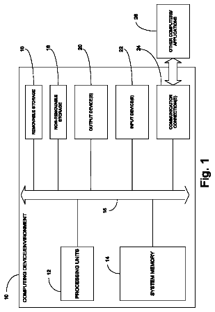
FIG. 3 is a diagram of example components of a device that corresponds to one or more devices of FIG. 2 ;
FIG. 4 is a flowchart of an example process for obtaining a label and transmitting the label;
FIG. 5A is a diagram of a data structure storing example values for a label header included in the label and related to the example process shown in FIG. 4 .
FIG. 5B is a diagram of a data structure storing example values for a use case flag included in the label and related to the example process shown in FIG. 4 ;
FIG. 5C is a diagram of a data structure storing example values for a data flow flag included in the label and related to the example process shown in FIG. 4 ;
FIG. 5D is a diagram of a data structure storing example values for an economy and lifecycle flag included in the label and related to the example process shown in FIG. 4 ;
FIG. 5E is a diagram of a data structure storing example values for a management and control flag included in the label and related to the example process shown in FIG. 4 ;
FIGS. 6A and 6B are diagrams of example labels relating to the example process shown in FIG. 4 ;
FIG. 7 is a flowchart of an example process for managing a smart device or an environment based on the label; and
FIGS. 8A and 8B are diagrams of an example implementation relating to the example process shown in FIG. 7 .
Detailed description of preferred embodiments
The following detailed description of example implementations refers to the accompanying drawings. The same reference numbers in different drawings may identify the same or similar elements.
Managing the IoT becomes more complex as the IoT grows and smart devices transmit data. For example, different hardware and software options and incompatible technological lifecycle time spans for smart devices may result in serious challenges for device orchestration, management, and network scaling. Implementations described herein provide a label including a universal, high-level labeling scheme that may facilitate managing the IoT.
FIGS. 1A and 1B are diagrams of an overview of an example implementation 100 described herein. In example implementation 100 , assume multiple smart devices each store a label including various flags.
As shown in FIG. 1A , the smart devices may transmit the labels to a server device (or another kind of device). The server device may receive the labels. Based on the labels, the server device may manage the smart devices and/or allocate resources within an environment. For example, server device may allocate local storage to store information for the smart devices, allocate bandwidth to be used by the smart devices, and/or provide power based on power requirements for the smart devices.
FIG. 1B illustrates an example of the label used in example implementation 100 having a universal labeling scheme including various flags. The label may include a use case flag, a data flow flag, an economy and lifecycle flag, and a management and control flag. The use case flag may indicate a kind of use for a smart device. The data flow flag may indicate a direction of data flow for a smart device. The economy and lifecycle flag may indicate service information for a smart device, energy information for a smart device, and/or redundancy mechanisms for a smart device. The management and control flag may indicate an administrative requirement for a smart device.
Accordingly, the server device may obtain information about different smart devices in an environment using the label (e.g., a universal label). Thus, the server device may manage multiple different kinds of smart devices and/or allocate resources in the environment based on the multiple different kinds of smart devices identified by the labels.
FIG. 2 is a diagram of an example environment 200 in which systems and/or methods described herein may be implemented. As shown in FIG. 2 , environment 200 may include a smart device 210 , a server device 220 , and a network 230 .
Smart device 210 may include a device capable of receiving and providing information, such as a label. For example, smart device 210 may include a mobile phone (e.g., a smart phone, a radiotelephone, a thermostat, an oven, etc.), a computing device (e.g., a desktop computer, a laptop computer, a tablet computer, a handheld computer, a camera, an audio recorder, a camcorder, etc.), an appliance (e.g., a refrigerator, a microwave, a stove, etc.), a medical device, a car, a light bulb, and/or a similar device. In some implementations, smart device 210 may include a communication interface that allows smart device 210 to receive information from and/or transmit information to server device 220 and/or another device in environment 200 . Additionally, or alternatively, smart device 210 may be any device with a processor, a memory, and a communication device. A processor, a memory, and/or a communication device may be added to or included in any object to make the object a smart device 210 . For example, a smart device 210 may be a shoe, a chair, a road, etc. In other words, smart device 210 may be any “thing” in the IoT.
Server device 220 may include one or more devices capable of processing and/or routing information. In some implementations, server device 220 may include a communication interface that allows server device 220 to receive information from and/or transmit information to other devices in environment 200 .
Network 230 may include one or more wired and/or wireless networks. For example, network 240 may include a cellular network, a public land mobile network (“PLMN”), a second generation (“2G”) network, a third generation (“3G”) network, a fourth generation (“4G”) network, a fifth generation (“5G”) network, a long term evolution (“LTE”) network, and/or a similar type of network. Additionally, or alternatively, network 270 may include a local area network (“LAN”), a wireless personal area network (“WPAN”), a wide area network (“WAN”), a metropolitan area network (“MAN”), a telephone network (e.g., the Public Switched Telephone Network (“PSTN”)), an ad hoc network, an intranet, the Internet, a fiber optic-based network, and/or a combination of these or other types of networks.
The number of devices and/or networks shown in FIG. 2 is provided for explanatory purposes. In practice, there may be additional devices and/or networks, fewer devices and/or networks, different devices and/or networks, or differently arranged devices and/or networks than those shown in FIG. 2 . Furthermore, two or more devices shown in FIG. 2 may be implemented within a single device, or a single device shown in FIG. 2 may be implemented as multiple, distributed devices. Additionally, one or more of the devices of environment 200 may perform one or more functions described as being performed by another one or more devices of environment 200 . Devices of environment 200 may interconnect via wired connections, wireless connections, or a combination of wired and wireless connections.
FIG. 3 is a diagram of example components of a device 300 that corresponds to one or more devices of FIG. 2 . Device 300 may correspond to smart device 210 and/or server device 220 . Additionally, or alternatively, smart device 210 and/or server device 220 may include one or more devices 300 and/or one or more components of device 300 .
As illustrated in FIG. 3 , device 300 may include a bus 310 , a processor 320 , a memory 330 , an input component 340 , an output component 350 , and/or a communication interface 360 .
Bus 310 may include a path that permits communication among the components of device 300 . Processor 320 may include a processor (e.g., a central processing unit, a graphics processing unit, an accelerated processing unit), a microprocessor, and/or another type of processing component (e.g., a field-programmable gate array (“FPGA”), an application-specific integrated circuit (“ASIC”), etc.) that interprets and/or executes instructions. Memory 330 may include a random access memory (“RAM”), a read only memory (“ROM”), and/or another type of dynamic or static storage device (e.g., a flash, magnetic, or optical memory) that stores information and/or instructions for use by processor 320 .
Input component 340 may include a component that permits a user to input information to device 300 (e.g., a touch screen display, a keyboard, a keypad, a mouse, a button, a switch, etc.). If device 300 corresponds to smart device 210 , input component 340 may also include a sensor for sensing information. For example, input component 340 may include a sensor, such as a camera, a microphone, an accelerometer, a gyroscope, a GPS device, a magnetometer, a gravity sensor, a rotational sensor, a temperature/thermal sensor, a proximity sensor, a light sensor, a pressure sensor, a humidity sensor, an infrared sensor, a radio wave sensor, a dual lens camera, and/or another component that permits smart device 210 to receive input and/or detect conditions in the vicinity of smart device 210 .
Output component 350 may include a component that outputs information from device 300 (e.g., a display, a speaker, one or more light-emitting diodes (“LEDs”), etc.).
Communication interface 360 may include a transceiver-like component, such as a transceiver and/or a separate receiver and transmitter that enables device 300 to communicate with other devices, such as via a wired connection, a wireless connection, or a combination of wired and wireless connections. For example, communication interface 360 may include an Ethernet interface, an optical interface, a coaxial interface, an infrared interface, a radio frequency (“RF”) interface, a universal serial bus (“USB”) interface, or the like.
Device 300 may perform various operations described herein. Device 300 may perform these operations in response to processor 320 executing software instructions included in a computer-readable medium, such as memory 330 . A computer-readable medium is defined as a non-transitory memory device. A memory device includes memory space within a single storage device or memory space spread across multiple storage devices.
Software instructions may be read into memory 330 from another computer-readable medium or from another device via communication interface 360 . When executed, software instructions stored in memory 330 may cause processor 320 to perform one or more processes described herein. Additionally, or alternatively, hardwired circuitry may be used in place of or in combination with software instructions to perform one or more processes described herein. Thus, implementations described herein are not limited to any specific combination of hardware circuitry and software.
The number of components shown in FIG. 3 is provided for explanatory purposes. In practice, device 300 may include additional components, fewer components, different components, or differently arranged components than those shown in FIG. 3 .
FIG. 4 is a flowchart of an example process 400 for obtaining a label and transmitting the label. In some implementations, one or more process blocks of FIG. 4 may be performed by smart device 210 . For example, smart device 210 may obtain a label, store the label, and transmit the label. Additionally, or alternatively, one or more process blocks of FIG. 4 may be performed by another device or a group of devices separate from or including smart device 210 .
The label may be a bit sequence used to store binary values and may include a label header and/or different flags. For example, the label may include a use case flag, a data flow flag, an economy and lifecycle flag, and/or a management and control flag. In some implementations, the label may include other flags not disclosed herein. An example of a label is described in more detail with respect to FIGS. 5A-5E .
As shown in FIG. 4 , process 400 may include obtaining the label (block 410 ). For example, smart device 210 may obtain the label. The label may be associated with smart device 210 and/or include information about smart device 210 .
A label generating device may create the label and send the label to smart device 210 . For example, a manufacturer of smart device 210 may create the label and transmit the label to smart device 210 . Smart device 210 may then receive the label from the label generating device.
In some implementations, smart device 210 may generate the label. Accordingly, smart device 210 may obtain the label by generating the label. Additionally, or alternatively, the label may be programmed and/or input into smart device during and/or after manufacture of smart device 210 .
Smart device 210 may obtain more than one label. For example, smart device 210 may have multiple functions. For instance, a smart phone may execute different applications or programs that serve different functions. Smart device 210 may obtain a label for each function and/or application. Additionally, or alternatively, smart device 210 may obtain a label that can be used for multiple functions and/or applications.
As further shown in FIG. 4 , process 400 may include storing the label (block 420 ). For example, smart device 210 may store the label in a memory of smart device 210 .
A label may be static and stored in a fixed manner that does not allow smart device 210 to change the label. Additionally, or alternatively, a label may be dynamic and stored in a manner allowing smart device 210 to change the label autonomously and/or based on a remote trigger (e.g., based on instructions received from server device 220 ). Smart device 210 may store more than one label. For example, smart device 210 may store labels for different functions and/or applications, and these labels may be static and/or dynamic.
In some implementations, smart device 210 may process the label. For example, the label may be configurable and smart device 210 may apply processing logic to the received label before storing the label. Additionally, or alternatively, the label may include information causing smart device 210 to execute processing. For example, the label may include information identifying sleep, wakeup, power on, and/or power off times. Accordingly, smart device 210 may enter an active mode, a standby mode, a power on mode, and/or a power off mode based on the label.
As further shown in FIG. 4 , process 400 may include transmitting the label (block 430 ). For example, smart device 210 may transmit the label to server device 220 and/or another smart device 210 .
In some implementations, smart device 210 may transmit the label once to register smart device 210 with server device 220 and/or another smart device 210 . Additionally, or alternatively, smart device 210 may periodically transmit the label to maintain registration in a local network. For example, smart device 210 may be in a local network and may transmit the label to server device 220 in the local network once to register the smart device 210 in the local network. Smart device 210 may periodically transmit the label to maintain registration in the local network. In other words, server device 220 may be informed that smart device 210 is still in the local network and has not been removed from the local network.
In some implementations, smart device 210 may include the label in every data packet smart device 210 transmits. For example, smart device 210 may include the label in a header, a footer, and/or a payload of a data packet.
In some implementations, smart device 210 may transmit the label when server device 220 or another device requests the label and/or reads the label from smart device 210 .
In some implementations, smart device 210 may transmit more than one label. For example, smart device 210 may transmit different labels for different functions and/or applications. Additionally, or alternatively, different labels may be transmitted at different times and/or at different frequencies.
While a series of blocks has been described with regard to FIG. 4 , the blocks and/or the order of the blocks may be modified in some implementations. Additionally, or alternatively, non-dependent blocks may be performed in parallel.
FIG. 5A is a diagram of a data structure 500 storing example values for a label header 510 included in a label and related to process 400 shown in FIG. 4 . Smart device 210 and/or server device 220 may store data structure 500 in a memory.
Label header 510 may indicate administrative information associated with the label. For example, label header 510 may include a version value indicating a version of the label, a catalogue value indicating whether flags in the label include relevant information, and/or a write value indicating whether the label is configurable. In some implementations, label header 510 may include a catalogue value for each flag in the label. Data structure 500 may associate the version value, the catalogue value, and/or the write value with descriptions used to interpret label header 510 .
Data structure 500 may include a version description field associated with a version value field, a catalogue description field associated with a catalogue value field, and/or a write description field associated with a write value field.
A version entry in data structure 500 may include a description in the version description field and a corresponding version value in the version value field. The description may indicate that the version value indicates a version of the label (e.g., a version name, a version number, etc.). In some implementations, each version value may correspond to a version of the label. Additionally, or alternatively, a predetermined version value (e.g., 255) may indicate the label should be ignored and/or not processed. As shown in FIG. 5A , the version value may have 255 different values (e.g., 1 to 255). In some implementations, the version value may have additional, fewer, or different values.
A catalogue entry in data structure 500 may include a description in the catalogue description field and a corresponding catalogue value in the catalogue value field. The description may indicate that a flag associated with the catalogue value is relevant or not relevant. For example, the catalogue value having a first value (e.g., 0) may indicate an associated flag (e.g., the use case flag, the data flow flag, the economy and lifecycle flag, and/or the management and control flag) may not be relevant and should be ignored. On the other hand, the catalogue value having a second value (e.g., 1) may indicate an associated flag (e.g., the use case flag, the data flow flag, the economy and lifecycle flag, and/or the management and control flag) may be relevant and should be used for processing. As shown in FIG. 5A , the catalogue value may have two different values (e.g., 0 and 1). In some implementations, the catalogue value may have additional, fewer, or different values.
Label header 510 may include more than one catalogue value. For example, label header 510 may include a catalogue value for each of the use case flag, the data flow flag, the economy and lifecycle flag, and/or the management and control flag. An order of the catalogue values in label header 510 may indicate which catalogue value corresponds to which flag. For example, a first catalogue value may correspond to the use case flag, a second catalogue value may correspond to the data flow flag, a third catalogue value may correspond to the economy and lifecycle flag, and/or a fourth catalogue value may correspond to the management and control flag. In some implementations, the order of the catalogue values may be different and correspond to different flags.
A write entry in data structure 500 may include a description in the write description field and a corresponding write value in the write value field. The description may indicate whether the label is configurable and/or whether the label is rewritable. For example, the write value having a first value (e.g., 0) may indicate that the label is not configurable and/or is not rewritable (e.g., fixed). On the other hand, the write value having a second value (e.g., 1) may indicate that the label is configurable and/or is rewritable (e.g., dynamic). As shown in FIG. 5A , the write value may have two different values (e.g., 0 and 1). In some implementations, the write value may have additional, fewer, or different values. For example, the write value may have a third value indicating the label is configurable and/or updatable autonomously. Additionally, or alternatively, the write value may have a fourth value indicating the label is configurable and/or updateable based on a remote trigger (e.g., based on instructions received from server device 220 and/or another remote device). It will be appreciated that these first, second, third, and fourth values are given as examples, and more than or fewer than the ones listed here may be used in the write value field of structure 500 .
Label header 510 may include a version value (e.g., 1 to 255) that is represented by 8 bits. In some implementations, greater than or less than 8 bits may represent the version value. Label header 510 may include a catalogue value (e.g., 0 or 1) that is represented by one bit. In some implementations, greater than one bit may represent the catalogue value. Additionally, or alternatively, label header 510 may include multiple catalogue values. For example, label header 510 may include seven catalogue values represented by seven bits (e.g., a catalogue value for each of the use flag, the data flow flag, the economy lifecycle flag, and/or the management and control flag, and three bits for possible flags to be added). In some implementations, label header 510 may include greater than or less than seven catalogue values represented by greater than or less than seven bits. Label header 510 may include a write value (e.g., 0 or 1) that is represented by one bit. In some implementations, more than one bit may represent the write value. Accordingly, label header 510 may have a length of two bytes (e.g., 16 bits). In some implementations, label header 510 may have a length greater than or less than two bytes.
In some implementations, label header 510 may have a value (001-255)(0-1)(0-1)(0-1)(0-1)(0-1)(0-1)(0-1)(0-1), where the first value represents a version value, the second through fourth values represent catalogue values for possible flags, the fifth through eighth values represent catalogue values for the use flag, the data flow flag, the economy lifecycle flag, and the management and control flag, and the ninth value represents a write value. For example, a value of 14700011110 may indicate the label is set to version 147, all of the use flag, the data flow flag, the economy lifecycle flag, and the management and control flag are relevant, and the label is not configurable.
Label header 510 may be used by server device 220 and/or smart device 210 to implement various version control mechanisms based on the version of the label. Additionally, or alternatively, label header 510 may indicate to server device 220 and/or smart device 210 which flags are relevant and include information that may be used for processing. Furthermore, label header 510 may be used by server device 220 and/or smart device 210 to determine if the label is configurable.
While FIG. 5A shows data structure 500 as having a particular number and arrangement of fields, in practice data structure 500 may include fewer fields, additional fields, or different fields than are shown in FIG. 5A .
FIG. 5B is a diagram of a data structure 520 storing example values for a use case flag 530 included in a label and related to process 400 shown in FIG. 4 . Smart device 210 and/or server device 220 may store data structure 520 in a memory.
Use case flag 530 may indicate system imminent behavior for use cases related to the kind of smart device 210 . In other words, use case flag 530 may indicate a kind of transmitter from which smart device 210 receives data and/or a kind of receiver to which smart device 210 transmits data. In some implementations, use case flag 530 may indicate a kind of communication used by the device. Data structure 520 may associate a value for use case flag 530 with a description used to interpret use case flag 530 .
Data structure 520 may include a description field and a value field associated with use case flag 530 . The description field may include information indicating a description and/or a type of use case. The value field may include a value included in use case flag 530 that identifies the use case. The values provided in FIG. 5B are example values and the values may be any values that identify the use cases. An entry in data structure 520 may include a description in the description field and a corresponding value in the value field.
As shown in FIG. 5B , data structure 520 may include entries for four different types of use cases for smart device 210 : machine-to-machine (M2M), machine-to-human (M2H), human-to-machine (H2M), and/or human-to-human (H2H). In some implementations, data structure 520 may include entries for other types of use cases.
An entry for the M2M use case may include a description, in the description field, indicating data is exchanged between machines and/or sent from a machine to a machine. In other words, a machine transmitter transmits data to a machine receiver. For example, a M2M use case may apply to a device on a car that sends data indicating driving behavior to an insurance company server and/or a navigation server. Use case flag 530 may have a first value, which identifies the M2M use case, in the value field (shown as value “U1” in FIG. 5B ).
An entry for the M2H use case may include a description, in the description field, indicating data is sent from a machine to a human. In other words, a machine transmitter sends data to a human receiver. A human receiver may receive the data through an output component 350 of the machine (e.g., a LED, a display, a speaker, a haptic feedback device, etc.). For example, a M2H use case may apply to a display that is advertising content to a user or a speaker emitting a sound to a user. Use case flag 530 may have a second value, which identifies the M2H use case, in the value field (shown as value “U2” in FIG. 5B ).
An entry for the H2M use case may include a description, in the description field, indicating data is sent from a human to a machine. In other words, a human transmitter sends data to a machine receiver. For example, a H2M use case may apply to a medical device that records medical information from a human (e.g., blood pressure, heart rate, etc.) Additionally, or alternatively, a H2M use case may apply to an input component 340 that a person uses to input information into a machine (e.g., a keyboard, a microphone, etc.). Use case flag 530 may have a third value, which identifies the H2M use case, in the value field (shown as value “U3” in FIG. 5B ).
An entry for the H2H use case may include a description, in the description field, indicating data is sent from a human to a human and/or exchanged between humans. In other words, a human transmitter sends data to a human receiver. For example, a H2H use case may apply to a person sending a text message to another person. In some implementations, the H2H use case may involve machines that transmit and/or receive the data as long as a human inputs the data and a human receives the data. Use case flag 530 may have a fourth value, which identifies the H2H use case, in the value field (shown as value “U4” in FIG. 5B ).
In some implementations, use case flag 530 may be represented by two bits assuming use case flag has four different possible values. However, use case flag 530 may have additional or fewer bits representing additional use cases, fewer use cases, and/or different use cases.
Use case flag 530 may improve social acceptance of the IoT by increasing transparency of devices. For example, people may be hesitant to accept potentially billions of objects in everyday life being smart objects with the ability to communicate information. However, use case flag 530 may be used by smart device 210 and/or server device 220 to present information to a user indicating a use case for smart device 210 and allow users to understand the use for smart device 210 .
Accordingly, a label, stored by smart device 210 , may include a value for use case flag 530 and smart device 210 may transmit the label. Server device 220 and/or another smart device 210 may receive the label including the value for use case flag 530 from smart device 210 . Thus, server device 220 and/or another smart device 210 may determine a description and/or type of use case for smart device 210 based on the value for use case flag 530 from data structure 520 .
While FIG. 5B shows data structure 520 as having a particular number and arrangement of fields, in practice data structure 520 may include fewer fields, additional fields, or different fields than are shown in FIG. 5B .
FIG. 5C is a diagram of a data structure 540 storing example values for a data flow flag 550 included in a label and related to process 400 shown in FIG. 4 . Smart device 210 and/or server device 220 may store data structure 540 in a memory. The term “data,” as used with regard to data flow flag 550 , may refer to data which is usage related, in contrast to control or management data. Likewise, the term “data flow,” or the like, may represent traffic of usage data.
Data flow flag 550 may include a data flow value indicating a direction of data flow, a data storage value indicating where data is stored, and/or a time period value indicating a time period data is stored. Data structure 540 may associate the data flow value, the data storage value, and/or the time period value of data flow flag 550 with descriptions used to interpret data flow flag 550 .
Data structure 540 may include a data flow description field associated with a data flow value field, a data storage description field associated with a data storage value field, and/or a time period description field associated with a time period value field.
A data flow entry in data structure 540 may include a description in the data field description field and a corresponding data flow value in the data flow value field. As shown in FIG. 5C , data structure 540 may include data flow entries for three types of data flows for smart device 210 : out, in, and bidirectional. However, data structure 540 may include data flow entries for other types of data flows.
A data flow entry for an out data flow may include a description, in the data flow description field, indicating data is transmitted by smart device 210 and no data is received via communication with another device. For example, a temperature sensor sending temperature data to server device 220 without receiving information back from server device 220 may store a label having a data flow flag with the data flow value indicating an out data flow. The data flow value in the data flow value field may have a first value for an out data flow (shown as value “D1” in FIG. 5C ).
A data flow entry for an in data flow may include a description, in the data flow description field, indicating data is received by smart device 210 and no data is transmitted by smart device 210 . For example, an in data flow may apply to a display that receives advertisements from server device 220 for displaying to a person, but that does not send data back to server device 220 . The data flow value in the data flow value field may have a second value for an in data flow (shown as value “D2” in FIG. 5C ).
A data flow entry for a bidirectional data flow may include a description, in the data flow description field, indicating data flows in both directions (i.e., data is received by smart device 210 and sent out by smart device 210 ). For example, a bidirectional data flow may apply to a navigation device that sends position data to a server and receives data indicating directions. The data flow value in the data flow value field may have a third value for a bidirectional data flow (shown as value “D3” in FIG. 5C ).
A data storage entry in data structure 540 may include a description in the data storage description field and a data storage value in the data flow value field. As shown in FIG. 5C , data structure 540 may include data storage entries for four types of data storage for smart device 210 : no data storage, unit data storage, local data storage, and/or remote data storage. However, data structure 540 may include data storage entries for other types of data storage.
A data storage entry for no data storage may include a description, in the data storage description field, indicating no data is stored. The data storage value in the data storage value field may have a first value for no data storage (shown as value “0” in FIG. 5C ).
A data storage entry for unit data storage may include a description, in the data storage description field, indicating data is stored in a memory of smart device 210 . The data storage value in the data storage value field may have a second value for unit data storage (shown as value “1” in FIG. 5C ).
A data storage entry for local data storage may include a description, in the data storage description field, indicating data is stored in a local network of smart device 210 . The data storage value in the data storage value field may have a third value for local data storage (shown as value “2” in FIG. 5C ).
A data storage entry for remote data storage may include a description, in the data storage description field, indicating data is stored remotely relative to smart device 210 . The data storage value in the data storage value field may have a fourth value for remote data storage (shown as value “3” in FIG. 5C ).
A time period entry in data structure 540 may include a description in the time period description field and a corresponding time period value in the time period value field.
A time period entry may include a description, in the time period description field, indicating a unit of time and/or a time period to store the data. For example, the time period description field may indicate a number of seconds, minutes, hours, days, weeks, months, and/or years to store the data. The time period value in the time period value field may indicate a number of time units (e.g., hours) to store the data. The time period value may be a value from 0 to n+1, where n indicates a maximum specified time period the data can be stored and n+1 indicates storing the data for an unlimited time. For example, the time period value may indicate a number of hours and n may be equal to 17520 (e.g., the equivalent of 2 years). Accordingly, a time period value of 17521 (i.e., n+1) may indicate storing the data for an unlimited time.
Data flow flag 550 may include a data flow value (e.g., D1, D2, or D3) that is represented by two bits. In some implementations, greater than or less than two bits may represent the data flow value. Data flow flag 550 may include a data storage value (e.g., 0, 1, 2, or 3) that is represented by two bits. In some implementations, greater than or less than two bits may represent the data storage value. Data flow flag 550 may include a time period value (e.g., 0 to n+1) that is represented by a number of bits depending on the value of n. For example, assuming n is equal to 17520 as previously discussed, the data flow value may be presented by 15 bits. In some implementations, greater than or less than 15 bits may represent the time period value.
In some implementations, data flow flag 550 may have a value D(1-3)(0-3)(0-n+1). For example, data flow flag 550 having a value D12n may represent a smart device 210 that sends data out with a requirement for local storage (on a server/gateway) for a time period n.
Data flow flag 550 may improve social acceptance of the IoT by increasing transparency of devices. For example, a user may be unsure what smart devices 210 around the user are transmitting data. However, data flow flag 550 may indicate to a user what kinds of data flows are used by an object and this may ease any privacy concerns a user has about the IoT. Additionally, or alternatively, data flow flag may allow for improved management of bandwidth allocation. For example, server device 220 may manage bandwidth allocation for a number of smart devices 210 . Data flow flag 550 may allow server device 220 to know how many smart devices 210 and which smart devices 210 need bandwidth to send or transmit data and allocate bandwidth accordingly. In some implementations, a local gateway may allocate dynamic bandwidth requirements over a fixed wide area network (WAN) or mobile network based on data flow flag 550 . Furthermore, data flow flag may 550 may provide insight in data storage requirements for a wireless private area network (WPAN) and could allocate resources dynamically.
Accordingly, a label, stored by smart device 210 , may include a value for data flow flag 550 and smart device 210 may transmit the label. Server device 220 and/or another smart device 210 may receive the label including the value for data flow flag 550 from smart device 210 . Thus, server device 220 and/or another smart device 210 may determine a kind of data flow, where data is stored, and/or a time period data is stored for smart device 210 based on the value/s for data flow flag 550 from data structure 540 .
While FIG. 5C shows data structure 540 as having a particular number and arrangement of fields, in practice data structure 540 may include fewer fields, additional fields, or different fields than are shown in FIG. 5C .
FIG. 5D is a diagram of a data structure 560 storing example values for an economy and lifecycle flag 570 included in the label and related to process 400 shown in FIG. 4 . Smart device 210 and/or server device 220 may store data structure 560 in a memory.
Economy and lifecycle flag 570 may include a service value indicating service information for smart device 210 , an energy value indicating energy information for smart device 210 , a redundancy value indicating redundancy mechanisms for smart device 210 , and/or an open value left open for future use. Data structure 560 may associate the service value, the energy value, the redundancy value, and/or the open value with descriptions used to interpret economy and lifecycle flag 570 .
Data structure 560 may include a service description field associated with a service value field, an energy description field associated with an energy value field, a redundancy description field associated with a redundancy value field, and/or an open description field associated with an open value field.
The description continues in the full USPTO document.
 Lapsed, fee not paid7 drawings