 Lapsed, fee not paid2 drawings
Consumer Products · US 9,754,459 B1
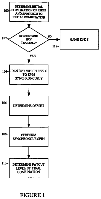
Slot machine with synchronized spinning reels
A slot machine that can spin two or more of the reels in unison.
US 9,755,444 B2 · Assignee: MOPHIE, INC. · Inventors: To; Nguyen et al.
Sheet 1 of 24 from the published document. All sheets in the USPTO PDF
A protective case can house a portable electronic device. The portable electronic device can have a switch (e.g., for switching an operational mode of the portable electronic device). The protective case can have a switch cover that engages the switch of the portable electronic device when the portable electronic device is in the protective case. The switch cover can be moved between positions corresponding to positions of the switch of the portable electronic device. As the switch cover is moved, the switch cover correspondingly moves the switch.
Field This application generally relates to covers for mechanical switches, and more particularly to protective cases for mobile electronic devices having switch covers configured to actuate mechanical switches on the mobile electronic devices. Description of the Related Art Many mobile devices (e.g., mobile phones, digital assistants, mobile communication devices, handheld video game devices, handheld computing devices, personal music/video/content players, navigation systems, sensors, and storage devices) may be expensive, may have fragile equipment such as breakable glass touchscreens and lenses, may have easily scuffed decorative finishes, may have delicate internal electronic components, and may have easily broken or lost buttons and/or switches. People have also become more and more dependent on the data, contacts, and calendars stored in their mobile devices, even as the devices s
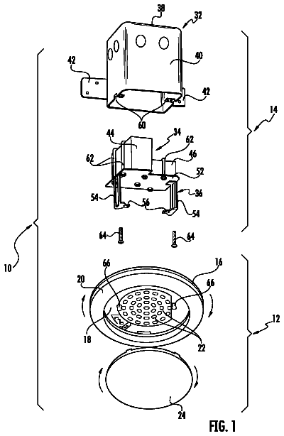
1 of 24 drawing sheets so far from the published document, cropped to the drawing. Every sheet is in the USPTO PDF.
What the patent claimed, word for word. All of it is now free to use.
Field
This application generally relates to covers for mechanical switches, and more particularly to protective cases for mobile electronic devices having switch covers configured to actuate mechanical switches on the mobile electronic devices.
Description of the Related Art
Many mobile devices (e.g., mobile phones, digital assistants, mobile communication devices, handheld video game devices, handheld computing devices, personal music/video/content players, navigation systems, sensors, and storage devices) may be expensive, may have fragile equipment such as breakable glass touchscreens and lenses, may have easily scuffed decorative finishes, may have delicate internal electronic components, and may have easily broken or lost buttons and/or switches. People have also become more and more dependent on the data, contacts, and calendars stored in their mobile devices, even as the devices shrink and incorporate more expensive and more sensitive components. These expensive devices and the critical stored data can be protected with a relatively inexpensive protective case. Additionally as the mobile device form factor shrinks, the mechanical controls can similarly shrink.
Additionally, such mobile devices are typically designed to satisfy the needs of a wide array of consumers. While some consumers are comfortable with no case or decorative cases providing minimal protection, for other consumers, these devices are frequently used in harmful environments such that external covers capable of protecting the internal device from liquid, dust, crushing, and impact are beneficial. Consequently, users who wish to protect their mobile device in harmful environments (e.g., military, law enforcement, construction workers, and outdoors enthusiasts) often protect their cases with bulky, durable cases.
One solution to access buttons through an external case is to include depressible pass-through buttons that do not directly expose the device, thereby providing additional protection without noticeable access ports. However, some mobile devices incorporate switches or toggles, which mechanically move from a first position to a second position. Sometimes the switches or toggles visibly identify the present status, such as through a 1 and 0 or red and green indicator. A depressible pass-through button on a case does not adequately control a switch or toggle on a mobile device and does not provide any visible identifier of the current switch or toggle status. Previous solutions often include pass-through holes in the case or thin, flexible membranes for switches and toggles. Pass-through holes and thin membranes reduce the protection provided by the case, and as the size of mobile devices shrinks, the space available to access a switch or toggle is more and more restricted, and any interference can negatively impact the accessibility of a switch or toggle. Additionally, very small switches sometimes require fingernail operation, and repetitive fingernail access on a membrane can damage or pierce the membrane, reducing the functionality and eliminating and waterproof or protective benefit. Further, pass-through holes and membranes frequently interrupt the aesthetics of the external case.
According to embodiments disclosed herein, a mobile device peripheral that incorporates a convenient switch cover for a mobile device switch that can protect a switch on the mobile device, and the switch cover can adjust position to fit over the mobile device switch regardless of the mobile device switch's position. The switch cover is capable of moving in the same direction as the mobile device switch and externally indicating the position of the covered mobile device switch.
According to embodiments disclosed herein, a switch cover corresponds to an underlying switch on a mobile device. A switch can be built into a mobile device. A switch cover can be built into a cover for the mobile device. The switch cover can have a switch base with an internal switch guide on an internal surface of the cover and an external feature on the external surface of the cover. The internal switch guide can be shaped to fit over (for example, engage and/or mate with) the mobile device's switch when the mobile device is inserted into a case (or shell) that can house the mobile device. The case can include an additional back-up battery that can transfer electrical charge to the mobile device. The switch cover can be freely movable with minimal resistance, such that when the switch cover is in a relative “up” position while the mobile device's switch is in a relative “down” position, the switch cover will move to slip over the mobile device switch, without adjusting the mobile device switch position. State differently, the up position cover moves into a down position to correspond to the down position of the switch, and the switch does not move from the down position to the up position, when the mobile device is inserted into the case. Such an adjusting movement of the cover can be achieved through the shape of the internal switch guide. The internal switch guide can have two guide rails that sandwich the switch when the mobile device is in the case. One end of the internal switch guide can be open so that the mobile device switch can slide in. In some embodiments, the other end of the internal switch guide can be closed to help position the cover at a desired position relative the switch and/or the mobile device.
The internal switch guide can be substantially u-shaped, and the guiderails of the U can be either parallel or divergent to facilitate switch capture and/or movement of the cover to correspond to the position of the switch. In some embodiments, at the open end of the switch guide, the ends of the guide rails from which the switch would enter the internal switch guide can be angled away from the a centerline between the two guide rails such that when the internal switch guide is slid over the switch, the angled ends contact the switch to move the cover to match a position of the switch as the angled ends slide against the switch without moving the switch, for example, causing the cover to linearly translate at a rate corresponding to the angle of the angled ends.
The switch base can be disposed in a cavity of a shell or case. Edges, walls, and/or flanges (for example, guiding end portions) of the switch base can be sandwiched between an internal wall and an external wall of the shell. The sandwiching of the edges of the switch base with minimal friction can allow the cover to move relatively freely within a desired range and/or plane without the switch base slipping out of the cavity. The linear motion within a plane can be further guided with a guide feature disposed on the switch base, such as an elevated feature that slides within a guide path on an internal wall and/or external wall of the case.
In some embodiments, a shell including a switch cover for use with a switch of a portable electronic device can include one or more of the following: a switch cover configured to move relative to the shell; and/or an opening in the shell engaging the switch cover while allowing the switch cover to move relative to the shell. The switch can include one or more of the following: a base having an inner surface and an outer surface, the inner surface configured to face a switch of a portable electronic device when the portable electronic device is in the shell, the outer surface configured to face away from the switch; and/or a guide on the inner surface of the base, the guide configured to engage the switch of the portable electronic device when the portable electronic device is in the shell. The switch cover is configured such that the guide moves the switch of the portable electronic device when the portable electronic device is in the shell and the switch cover is moved relative to the shell. Stated differently, when the portable electronic device is in the shell and the switch cover is moved relative to the shell, the guide moves the switch of the portable electronic device.
In some embodiments, the shell can include one or more of the following: the shell comprises a cavity about the opening in shell, the cavity engaging the switch cover to allow movement of the switch cover along a desired direction; the shell comprises an outer wall and an inner wall, the outer wall comprising an outer wall recess formed in the outer wall, the inner wall comprising an inner wall recess formed in the inner wall, and wherein the outer wall recess and the inner wall recess form the cavity about the opening in the shell; the cavity engages the base of the switch cover, the cavity shaped to correspond to a shape of the base to allow movement of the base along a desired direction, while inhibiting at least one of movement of the switch cover along other directions or rotational movement of the switch cover; the base comprises a guiding end portion, the cavity engaging the guiding end portion to guide the base along the desired direction; the base comprises two or more guiding end portions, the cavity engaging at least one of the guiding end portions to guide the base along the desired direction and to inhibit movement of the base beyond a perimeter of the cavity; the base comprises a protruding portion configured to engage the shell to guide movement of the switch cover along the desired direction; the protruding portion is on the inner surface of the base, the protruding portion engaging the inner wall of the shell to guide movement of the switch cover along the desired direction; the inner wall comprises a guiding track, and the protruding portion protrudes into the guiding track to guide movement of the switch cover in the desired direction along the guiding tracks; the shell further comprises spacers positioned between the outer wall and the inner walls to maintain a predetermined width of the cavity between the outer wall recess and the inner wall recess; the guide comprises a first guiderail on the inner surface of the base and a second guiderail on the inner surface of the base, the first guiderail corresponding to a first side of the switch of the portable electronic device, the second guiderail corresponding to a second side of the switch of the portable device, the first side of the switch opposite the second side of switch, wherein when the switch cover is moved in a first direction, the first guiderail pushes the first side of the switch to move the switch toward a first switch position, and wherein when the switch cover is moved in a second direction, the second guiderail pushes the second side of the switch to move the switch toward a second switch position; the first and second guiderails form a pathway between the first and second guiderails configured such that the switch slides between the first and second guiderails when the portable electronic device is being inserted into the shell; the first and second guiderails comprise divergent ends, wherein at least one of the divergent ends contact the switch when the portable electronic device is being inserted into the shell, and wherein the divergent ends facilitate positioning the switch cover to correspond to a position of the switch as the portable electronic device is inserted into the shell; the base comprises a back support on the inner surface of the base, wherein the guide and the back support have surfaces facing the portable electronic device when the portable electronic device is in the shell, and wherein the surfaces are on a same plane to position the switch cover at a predetermined distance from the portable electronic device; the predetermined distance from the portable electronic device is constant between positions of the switch cover; the switch cover comprises a handle on the outer surface to allow a user to move the switch cover relative to the shell; the switch cover comprises a switch cover visual indicator that, when the portable electronic device is in the shell, corresponds to a switch visual indicator that indicates an operational mode of the portable electronic device; the switch cover visual indicator is not visible to a user in a first position of the switch cover, and wherein the visual indicator is visible to the user in a second position of the switch cover; the shell houses the portable electronic device and the guide engages the switch of the portable electronic device; movement for the switch is a linear translation; and/or movement for the switch cover is a linear translation.
In some embodiments, a protective case for use with a mobile electronic device having a switch that is configured to move between a first switch position and a second switch position can include one or more of the following: a housing configured to at least partially enclose the mobile electronic device; and/or a switch cover movable between a first position and a second position. The switch cover is configured to move the switch to the first switch position when the switch cover is moved to the first position. The switch cover is configured to move the switch to the second switch position when the switch cover is moved to the second position.
In some embodiments, the protective case can include one or more of the following: the shell comprises a cavity about the opening in shell, the cavity engaging the switch cover to allow movement of the switch cover between the first and second positions; the housing comprises an outer wall and an inner wall, the outer wall comprising an outer wall recess formed in the outer wall, the inner wall comprising an inner wall recess formed in the inner wall, and wherein the outer wall recess and the inner wall recess form the cavity in the housing; the cavity engages a base of the switch cover, the cavity shaped to correspond to a shape of the base to allow movement of the base between the first and second positions corresponding to the first and second switch positions, while inhibiting at least one of movement of the switch cover along other directions or rotational movement of the switch cover; the base comprises a guiding end portion, the cavity engaging the guiding end portion to guide the base between the first and second positions; the base comprises two or more guiding end portions, the cavity engaging at least one of the guiding end portions in the first position or the second position; the base comprises a protruding portion configured to engage the housing to guide movement of the switch cover between the first and second positions; the protruding portion engages the inner wall of the housing to guide movement of the switch cover between the first and second positions; the inner wall comprises a guiding track, and the protruding portion extends into the guiding track to guide movement of the switch cover between the first and second positions along the guiding tracks; the housing further comprises spacers positioned between the outer wall and the inner walls to maintain a predetermined width of the cavity between the outer wall recess and the inner wall recess; the switch cover comprises a first guide on an inner surface of the switch cover and a second guide on the inner surface of the switch cover, the inner surface configured to face the mobile electronic device, the first guide corresponding to a first side of the switch of the mobile electronic device, the second guide corresponding to a second side of the switch of the portable device, the first side of the switch opposite the second side of switch, wherein when the switch cover is moved in a first direction, the first guide pushes the first side of the switch to move the switch toward a first switch position, and wherein when the switch cover is moved in a second direction, the second guide pushes the second side of the switch to move the switch toward a second switch position; the first and second guides form a pathway between the first and second guides configured such that the switch to slide between the first and second guides when the mobile electronic device is being inserted into the housing; the first and second guides comprise divergent ends, wherein at least one of the divergent ends contact the switch when the mobile electronic device is being inserted into the housing, and wherein the divergent ends facilitate positioning the switch cover to correspond to a position of the switch as the mobile electronic device is inserted into the housing; the switch cover comprises a back support facing the mobile electronic device when the mobile device is in the housing, wherein the back support comprises a flat surface to position the switch cover at a predetermined distance from the mobile electronic device; the predetermined distance from the mobile electronic device is constant between the first and second position; the switch cover comprises a handle on the outer surface to allow a user to move the switch cover between the first and second positions; the switch cover comprises a switch cover visual indicator that, when the mobile electronic device is in the housing, corresponds to a switch visual indicator that indicates an operational mode of the mobile electronic device; the switch cover visual indicator is not visible to a user in the first position of the switch cover, and wherein the visual indicator is visible to the user in the second position of the switch cover; the housing at least partially encloses the mobile electronic device and the switch cover operably connects to the switch of the mobile electronic device; movement for the switch between the first switch position and the second switch position is a linear translation; and/or movement for the switch cover between the first position and the second position is a linear translation.
In some embodiments, a cover for a switch can including one or more of the following: a switch base having a first surface facing toward the switch and a second surface facing away from the switch; an internal switch capture guide, on the first surface, with a first guide rail that corresponds to a first side of the switch and a second guide rail corresponding to a second side of the switch when the switch is disposed in the cover; and/or an external feature on the second surface approximately corresponding to the position of the switch.
In some embodiments, the cover can include one or more of the following: an imaginary line from the first guide rail to the second guide rail would align with a direction that the switch moves; the internal switch capture guide has at least one open side; the internal switch capture guide approximates a U-shape; the two guide rails are slightly divergent such that when the internal switch capture guide is slid over a switch, the cover will move to match a position of the switch; the two guide rails are substantially parallel, but the ends are angled in a way that when the internal switch capture guide is slid over a switch, the cover will move to match a position of the switch; the switch base is disposed in a cavity in a shell; a portion of the switch base is sandwiched between an internal wall and an external wall of the shell; the portion of the switch base is the entire outline of the switch base; the switch base can move relative to the shell in the direction that the switch moves; the switch base incorporates a directional guide feature; the directional guide feature is a raised portion on the switch base that corresponds to a path in the shell; the path in the shell is parallel to the direction that the switch moves; the external feature mirrors a shape of the switch; the switch base is substantially planar; and/or the internal switch capture guide adjusts to fit over the switch regardless of switch orientation.
In some embodiments, the cover can include one or more of the following: an imaginary line from the first guide rail to the second guide rail aligns with a direction that the switch is configured to move; the internal switch capture guide has at least one open side for accepting the switch; the internal switch capture guide approximates a U-shape; the first and second guide rails are slightly divergent such that when the internal switch capture guide is slid over the switch, the cover will move to match a position of the switch; the first and second guide rails are substantially parallel, but ends of the first and second guide rails are angled in a way that when the internal switch capture guide is slid over the switch, the cover will move to match a position of the switch; the switch base is disposed in a cavity in a shell; a portion of the switch base is sandwiched between an internal wall and an external wall of the shell; the portion of the switch base is an entire outline of the switch base; the switch base can move relative to the shell in a direction that the switch is configured to move; the switch base incorporates a directional guide feature; the directional guide feature is a raised portion on the switch base that corresponds to a path in the shell; the path in the shell is parallel to the direction that the switch is configured to move; the external feature mirrors a shape of the switch; the switch base is substantially planar; and/or the internal switch capture guide adjusts to fit over the switch regardless of switch orientation.
In some embodiments, a case for a mobile device can incorporate the cover, and the switch can be attached to the mobile device. The internal switch capture guide can adjust to fit over the switch regardless of switch orientation when the mobile device is inserted into the case. The case can include a battery. In some embodiments, the battery of the case can charge the mobile device.
The foregoing is a summary and contains simplifications, generalization, and omissions of detail. Those skilled in the art will appreciate that the summary is illustrative only and is not intended to be in any way limiting. Other aspects, features, and advantages of the devices and/or processes and/or other subject matter described herein will become apparent in the teachings set forth herein. The summary is provided to introduce a selection of concepts in a simplified form that are further described below in the Detailed Description. This summary is not intended to identify key features or essential features of any subject matter described herein.
The foregoing and other features of the present disclosure will become more fully apparent from the following description, taken in conjunction with the accompanying drawings. Understanding that these drawings depict only some embodiments in accordance with the disclosure and are, therefore, not to be considered limiting of its scope, the disclosure will be described with additional specificity and detail through use of the accompanying drawings.
FIG. 1A is a side, top, perspective view of an example embodiment of a shell or case having a switch cover in a first position.
FIG. 1B is a detailed view of a portion of the shell of FIG. 1A .
FIG. 2A is a side, top, perspective view of an example embodiment of a shell or case having a switch cover in a second position.
FIG. 2B is a detailed view of a portion of the shell of FIG. 2A .
FIG. 3A is a side, top, perspective view of an example embodiment of a shell or case having an opening.
FIG. 3B is a side, top, perspective view of an example embodiment of a shell or case with a battery.
FIG. 4 is an inner, side, top, perspective view of an example embodiment a shell.
FIG. 5 is a side, top, perspective view of an example embodiment of a shell.
FIG. 6 is a side, top, perspective view of an example embodiment of an inner wall of a shell with a mobile device.
FIG. 7 is a side, top, perspective view of an example embodiment of an inner wall of a shell with a switch cover in a first position.
FIG. 8 illustrates an example embodiment of an inner wall of a shell with a switch cover in a second position.
FIG. 9 is an inner side, top, perspective view of an example embodiment of an outer wall of a shell.
FIG. 10 is an inner side, top, perspective view of an example embodiment of an outer wall of a shell with a switch cover in a first position.
FIG. 11 illustrates an example embodiment of an outer wall of a shell with a switch cover in a second position.
FIGS. 12-15 illustrate an example embodiment of a switch cover.
FIGS. 16-19 illustrate another example embodiment of a switch cover.
FIGS. 20A-B and 21 A-B illustrate an example embodiment of a switch cover incorporated into a shell.
FIGS. 22A-B show an example embodiment of a partial cutout view of a shell with a mobile device being inserted into the shell.
FIGS. 23A-B show an example embodiment of a partial cutout view of a shell with a mobile device being inserted into the shell.
FIG. 24 is a side, perspective cross-sectional view of an example embodiment of a shell with a mobile device.
FIG. 25 is a cross-sectional top view of an example embodiment of a switch cover in a shell.
FIG. 26 is a cross-sectional top view of another example embodiment of a switch cover in a shell.
In the following description, reference is made to the accompanying drawings, which form a part hereof. In the drawings, similar symbols typically identify similar components, unless context dictates otherwise. The illustrative embodiments described in the description and drawings are not meant to be limiting. Other embodiments may be utilized, and other changes may be made, without departing from the spirit or scope of the subject matter presented here. It will be readily understood that the aspects of the present disclosure, as generally described herein, and illustrated in the Figures, may be arranged, substituted, combined, and designed in a wide variety of different configurations, all of which are explicitly contemplated and made a part of this disclosure.
Further, the following description contains simplifications, generalization, and omissions of detail. Those skilled in the art will appreciate that the description is illustrative only and is not intended to be in any way limiting. This description is not intended to identify key features or essential features of any subject matter described herein.
Various embodiments disclosed in this application generally relate to covers for mechanical switches, particularly to covers for mechanical switches on mobile devices (for example, smart phones). The covers can be incorporated into cases or shells protecting the mobile device. The covers can allow for convenient access to a mobile device switch or toggle (for example, without reducing protection, interrupting aesthetic, and/or reducing performance/accessibility).
FIG. 1A is a side, top, perspective view of an example embodiment of a shell 100 (for example, a case or a battery case). The shell or case 100 can be used to protect a portable electronic device 119 (e.g., see FIG. 6 ). The portable electronic device can include a mobile device, mobile phone, or tablet. The portable electronic device 119 can have a switch or toggle 121 built into the mobile device 119 (e.g., see FIGS. 6, 22A -B, and 23 A-B). A switch cover 102 can be integrated into the shell or case 100 . The switch cover 102 can be positioned to engage and/or mate with the switch 121 of the mobile device 119 as discussed herein. The shell 100 can have other features to engage and/or mate with other controls of the mobile device 119 . For example, as illustrated in FIG. 1A-B , the shell 100 can have volume buttons and/or rockers 103 . The volume buttons 103 can engage and/or mate with volume controls of the mobile device 119 .
FIG. 1B is a partial view of an embodiment of a shell 100 illustrating an enlarged view of the switch cover 102 . FIG. 1B illustrates the switch cover 102 in a first position. The switch cover 102 can move in a linear fashion or have a linear translational movement as discussed herein. For example, the switch cover 102 can move up and down. In some embodiments, the switch cover 102 can move side to side. The first position as illustrated in FIG. 1B can be considered an up position. References to up and down can refer to an orientation in which the screen (for example, touchscreen) of the mobile device 119 would face upward, even though the case 100 and mobile device 119 could be positioned in various other orientations during use. The up position, or first position, can correspond to the switch cover 102 positioning the switch 121 of the mobile device 119 into a normal (e.g., not silent or auditory) mode of the mobile device 119 .
The switch cover 102 can have a handle 104 , for example, an extension or protrusion as discussed herein. The handle 104 can be an elongated shape (for example, a bar shape) to provide a lever or gripping portion to facilitate linearly translating the switch cover 102 by the user, although various other shapes can be used. In some embodiments, the handle 104 can protrude beyond a periphery of the shell 100 to facilitate gripping of the switch cover 102 by the user in order to move (e.g., to linearly translate) the switch cover 102 as discussed herein. In some embodiments, the switch cover 102 can be flush with the periphery of the shell 100 or recessed below the periphery of the shell 100 , while still allowing the user to engage the cover 102 to move (e.g., linearly translate) the cover 102 .
FIG. 2A is a side, top, perspective view of an example embodiment of a shell 100 . FIG. 2B is a partial view of an embodiment of the shell 100 illustrating an enlarged view of the switch cover 102 . FIG. 2B illustrates the switch cover 102 in a second position. The second position as illustrated in FIG. 2B can be considered a down position. The down position or second position can correspond to the switch cover 102 positioning the switch 121 of the mobile device 119 into a quiet (e.g., vibrate or silent) mode of the mobile device 119 . Other configurations are possible. For example, the up position or first position of the switch cover can be configured to position the switch 121 into the quiet (e.g. vibrate or silent) mode, and the down position or second position can be configured to position the switch 121 into the normal (e.g., not silent or auditory) mode.
FIG. 3A is a side, top, perspective view of an example embodiment of an opening 106 in the shell or case 100 . The opening (for example, cutout or lumen) 106 can be shaped to house accept, engage, and/or mate with the switch cover 102 as discussed herein. The opening 106 can be generally rectangular or square. In some embodiments, the opening 106 can be other suitable shapes to correspond to the shape or shapes of the switch cover 102 . For example, the opening 106 may be generally round, cylindrical, and/or a combination of shapes, such as rectangular and having rounded or circular sides or corners. The opening 106 can have open ends on both sides to accept the switch cover 102 . The switch cover 102 can be inserted into the opening 106 and secured while allowing movement of the cover 102 as discussed herein. The opening 106 can be positioned in the shell 100 such that when the opening 106 houses the switch cover 102 and the mobile device 119 is inserted into the shell 100 , the switch cover 102 can engage or toggle the switch 121 of the mobile device 119 as discussed herein.
In some embodiments, the shell 100 may be made or formed from two or more walls. As illustrated in FIG. 3A , the shell may comprise an outer wall 108 and inner wall 110 . The outer wall 108 may envelope and/or cover wholly or partially the inner wall 110 . The outer wall 108 may provide protection for the shell 100 , components of the shell 100 (for example, the cover 102 ), and/or the mobile device 119 inserted therein. The inner wall 110 may be shaped and sized to accept the mobile device 119 and secure the mobile device 119 in a predetermined position within the shell 100 .
FIG. 3B is a side, top, perspective view of an example embodiment of shell or case 100 with a battery 109 . The case 100 can include a battery 109 (e.g., housed between the inner wall 110 and the outer wall 108 ). The battery 109 is illustrated by dashed lines in FIG. 3B , showing an example location for the battery 109 in the case 100 . The case 100 can include an electrical connector 111 that is electrically coupled to the battery 109 and configured to engage a port on the mobile device 119 such that the battery 109 of the case 100 can be electrically connected to the mobile device 121 to selectively charge the mobile device 121 when, for example, an internal battery of the mobile device 121 is depleted of charge or low on power.
Returning to FIG. 3A , the opening 106 can be formed from two corresponding openings in the outer wall 108 and the inner wall 110 . The outer wall 108 can have an outer opening (for example, cutout or lumen) 112 to accept and/or engage the switch cover 102 as discussed herein. The outer opening 112 can be sized and shaped to allow a desired motion of the switch 102 , and in particular the handle 104 , as discussed herein. For example, the outer opening 112 can be sized and shaped to allow and/or permit the movement of the handle 104 by the user to move the cover 102 into a desired position (for example, a first or second position as discussed herein). The outer opening 112 can be generally rectangular or square. In some embodiments, the outer opening 112 can be other suitable shapes to correspond to the shape of the switch cover 102 . For example, the outer opening 112 may be generally round, cylindrical, and/or a combination of shapes, such as rectangular and having rounded or circular sides or corners. In some embodiments, the outer opening 112 can be sized and shaped to accept the handle 104 of the cover 102 to protrude through the outer opening 112 and allow movement of the handle 104 to position the cover 102 as discussed herein.
The inner wall 110 can have an inner opening (for example, cutout or lumen) 114 to accept and/or engage the switch cover 102 as discussed herein. The inner opening 114 can be sized and shaped to allow a desired motion of the switch 102 , and in particular the internal switch guide 130 (see FIGS. 12-19 ) as discussed herein. For example, the inner opening 114 can be sized and shaped to allow and/or permit the movement of the internal switch guide 130 to move the switch 121 of the mobile device 119 into a desired position (for example, a first or second position as discussed herein).
FIG. 4 is an inner, side, top, perspective view of an example embodiment a shell or case 100 . As discussed in reference to FIG. 3A , the shell 100 can have an outer wall 108 and an inner wall 110 with an outer opening 112 and an inner opening 114 , respectively. As illustrated in FIG. 4 , the inner opening 114 can be formed in or housed in a channel 115 formed in the inner wall 110 . The channel 115 can be a relatively thinned wall region of the inner wall 110 . The cannel 115 can be formed in the inner wall 110 along a side of the shell 100 . The channel 115 can span a majority of the side of the shell 100 . The span of the channel 115 can correspond to aligning the switch 121 and other controls of the mobile device 119 such that the cover 102 can engage the switch 121 as discussed herein and the volume rockers 103 can engage the volume controls of the mobile device 119 .
The channel 115 can provide space or clearance between the inner wall 110 and the mobile device 119 . The clearance provided by the channel 115 can allow for functionality, engagement, and/or mating of the switch cover 102 and other control element(s) (for example, volume controls 103 ) with the switch 121 and other control element(s) of the mobile device 119 as discussed herein. For example, the channel 115 can allow and/or facilitate the mobile device 119 to be inserted into the shell 100 when the switch 121 protrudes beyond a periphery of the mobile device 119 . Similarly, the channel 115 can allow and/or facilitate insertion of the mobile device 119 into the shell 100 when other mobile control element(s) (for example, volume controls) of the mobile device 119 protrude beyond the periphery of the mobile device 119 .
FIG. 5 is a side, top, perspective view of an example embodiment of a shell 100 . An inner opening 114 can be formed in the inner wall 110 of the shell 100 . The inner opening 114 can be generally rectangular or square. In some embodiments, the inner opening 114 can be other suitable shapes to correspond to the shape of the switch cover 102 . For example, the inner opening 114 may be generally round, cylindrical, and/or a combination of shapes, such as rectangular and having rounded or circular sides or corners. As illustrated in FIGS. 3A and 4 , the outer opening 112 and inner openings 114 can correspond in shape. Stated differently, the outer opening 112 and inner opening 114 can have similar shapes (for example, rectangular as illustrated). In some embodiments, the outer opening 112 and inner opening 114 may be different shapes to correspond to and accept/allow movement of the handle 104 and/or internal switch guide 130 , respectively, as discussed herein.
The inner opening 114 can be formed in the inner wall 110 at a relatively thinned wall region 116 of the inner wall 110 . The thinned wall region 116 can also be considered an inner wall recess 116 about or around the inner opening 114 . The inner wall recess 116 can correspond with or be positioned at a region corresponding to the channel 115 of the inner wall 114 (e.g., see FIG. 4 ). In some embodiments, the corresponding positions (directly opposite sides of the inner wall 114 ) of the channel 115 and the inner wall recess 116 can form a relatively thin or thinnest portion of the inner wall 114 about the periphery of the shell 100 . The thin region of the corresponding positions of the channel 115 and the inner wall recess 116 can reduce the size and bulk of the case 100 , as well as the switch cover 102 spanning a reduced size of the case 100 , while still allowing for the functionality and engagement of switch 121 as discussed herein.
The inner wall recess 116 can be shaped and sized to house accept, engage, and/or mate with a base 126 (see FIGS. 12-19 ) of the switch cover 102 . The inner wall recess 116 can have recess edges or walls 118 that house the base 126 of the switch cover 102 . For example, inner wall recess edges 118 can be positioned to permit movement of the cover 102 between the first and second positions (for example, up and down), while substantially restricting or inhibiting movement of the cover 102 in other directions relative to the movement between the first and second positions (for example, substantially restricting or inhibiting side to side or rotational movement of the switch cover 102 ). The inner wall recess edge 118 can connect the inner wall recess 116 to the inner wall 110 . The inner wall recess edges 118 can be substantially perpendicular to a plane(s) formed by the inner wall 110 and/or the inner wall recess 116 . The angle of the inner wall recess edges 118 from the inner wall recess 116 to the inner wall 110 can correspond to an angle of walls or edges of the base 126 of the cover 102 .
The description continues in the full USPTO document.
About 6,789 words. The USPTO PDF has it with every drawing.
Fees are due 3.5, 7.5 and 11.5 years after grant. This patent expired on September 5, 2025, so the fee marked "not paid" was the one that went unpaid.
PROTECTIVE CASE WITH SWITCH COVER
Filed Feb 2014 · published Aug 2014Protective case with switch cover
Filed Feb 2014 · granted Sep 2017Earlier publications, parents and continuations. None of them can still be enforced, or this patent would not be listed.
Prior art cited by the examiner or applicant. Useful when you check your own idea for novelty.
Everything on this page comes from the documents linked above.