Cross reference to related applications
This is the U.S. national stage of application No. PCT/JP2015/056479, filed on Mar. 5, 2015. Priority under 35 U.S.C. §119(a) and 35 U.S.C. §365(b) is claimed from Japanese Application No. 2014-055245, filed Mar. 18, 2014, the disclosure of which is incorporated herein by reference.
Technical field
At least an embodiment of the present invention relates to a card conveying mechanism structured to convey a card. Further, at least an embodiment of the present invention relates to a card issuing device which includes the card conveying mechanism.
Background
Conventionally, a card issuing device structured to issue a card in which predetermined information is recorded has been known (see, for example, Patent Literature 1). The card issuing device described in Patent Literature 1 includes a card reader part structured to perform reproduction and the like of information recorded in a card, a plurality of card stack parts in which cards before issue are stacked and accommodated, a card turning part in which a card is turned, and a card conveyance part structured to convey a card between the card reader part, the plurality of the card stack parts and the card turning part. The card reader part, the plurality of the card stack parts, the card turning part and the card conveyance part are placed on a main body base.
Further, in the card issuing device described in Patent Literature 1, the card conveyance part includes a carriage which is linearly moved in a horizontal direction, and a drawing mechanism structured to draw a card into an inside of the carriage and to send out the card from the inside of the carriage. The carriage is movable in a short-side direction (width direction) of a card formed in a substantially rectangular shape. The card turning part includes a drive roller, a driven roller which is oppositely disposed to the drive roller, and an attaching member to which the drive roller and the driven roller are rotatably attached. Further, the card turning part includes a drive mechanism structured to drive the drive roller and a turning mechanism structured to turn the attaching member.
Patent literature
[PTL 1] Japanese Patent Laid-Open No. 2007-41635
The card issuing device described in Patent Literature 1 includes the card conveyance part and thus a card can be conveyed in a horizontal direction (specifically, in a short-side direction of a card). Further, since the card issuing device includes the card turning part, a longitudinal direction of a card can be inclined with respect to the horizontal direction by utilizing the card turning part and, therefore, various processes can be performed on the card. However, in the card issuing device, the card conveyance part having the carriage and the card turning part having the attaching member are separately provided and placed on the main body base and thus an area of the main body base is large and, as a result, installation area of the card issuing device becomes wide.
Summary
Therefore, in view of the problem described above, at least an embodiment of the present invention provides a card conveying mechanism capable of reducing an installation area of a host apparatus to which the card conveying mechanism is mounted even when a card is capable of being conveyed in a horizontal direction, a card is capable of being set in parallel to the horizontal direction, and a card is capable of being inclined with respect to the horizontal direction. Further, at least an embodiment of the present invention provides a card issuing device including the card conveying mechanism.
To achieve the above, at least an embodiment of the present invention provides a card conveying mechanism including a card holding part having a drawing and sending-out mechanism structured to perform drawing and sending out a card, the card holding part being configured to temporarily hold the card in its inside, a drawing and sending-out drive mechanism structured to drive the drawing and sending-out mechanism, a carriage on which the card holding part is mounted, a carriage drive mechanism structured to linearly move the carriage in a horizontal direction which is perpendicular to a drawing direction of the card into the card holding part, and a turning mechanism structured to turn the card holding part with respect to the carriage with the moving direction of the carriage as an axial direction of turning.
The card conveying mechanism in at least an embodiment of the present invention includes a carriage drive mechanism structured to linearly move the carriage on which the card holding part is mounted in a horizontal direction and a turning mechanism structured to turn the card holding part with respect to the carriage with the moving direction of the carriage as an axial direction of turning. Therefore, according to at least an embodiment of the present invention, a card held by the card holding part is capable of being conveyed in the horizontal direction, and a card held by the card holding part is capable of being set in parallel to the horizontal direction and being inclined with respect to the horizontal direction. Further, in at least an embodiment of the present invention, the card holding part mounted on the carriage is linearly moved in the horizontal direction and is turned with the moving direction of the carriage as an axial direction of turning. Therefore, in comparison with a case that a card holding part linearly moved in the horizontal direction and a card holding part turned with the moving direction of the carriage as an axial direction of turning are separately provided from each other, the size of the card conveying mechanism can be made small and an installation area of the card conveying mechanism can be reduced. Accordingly, in at least an embodiment of the present invention, even when a card can be conveyed in the horizontal direction and a card can be set in parallel to the horizontal direction or inclined with respect to the horizontal direction, an installation area of a host apparatus on which the card conveying mechanism is mounted can be reduced.
In at least an embodiment of the present invention, it is preferable that the card conveying mechanism includes two or more card holding parts which are disposed so as to overlap with each other in an upper and lower direction and, when the card holding parts are turned to predetermined positions by the turning mechanism, the card is capable of being transferred between the card holding parts in the upper and lower direction. According to this structure, a card is capable of being conveyed in an upper and lower direction.
In at least an embodiment of the present invention, it is preferable that two or more card holding parts are mounted on a common carriage so as to overlap in the upper and lower direction. According to this structure, in comparison with a case that carriages on which each of two or more card holding parts is mounted are individually provided, the structure of the card conveying mechanism can be simplified.
In at least an embodiment of the present invention, it is preferable that the card conveying mechanism includes a first card holding part and a second card holding part as the card holding part, the turning mechanism includes one turning motor which is a drive source and, when the turning motor is rotated, the first card holding part and the second card holding part are turned together. According to this structure, the first card holding part and the second card holding part can be turned by one turning motor and thus the structure of the turning mechanism can be simplified. Further, according to this structure, alignment of the first card holding part with the second card holding part can be performed by controlling the one turning motor when a card is transferred between the first card holding part and the second card holding part in the upper and lower direction. Therefore, the card conveying mechanism is easily controlled when a card is conveyed in the upper and lower direction.
In at least an embodiment of the present invention, for example, the turning mechanism includes a first turning pulley which is fixed to a turnable shaft fixed to the first card holding part, a second turning pulley which is fixed to a turnable shaft fixed to the second card holding part, and a turning belt which is stretched over the first turning pulley and the second turning pulley. When the turning motor is rotated, the turning belt is turned and thereby the first card holding part and the second card holding part are turned together.
In at least an embodiment of the present invention, it is preferable that the card conveying mechanism includes, as the card holding part, a first card holding part and a second card holding part, the first card holding part includes a first drawing and sending-out mechanism as the drawing and sending-out mechanism, and the second card holding part includes a second drawing and sending-out mechanism as the drawing and sending-out mechanism. The drawing and sending-out drive mechanism includes one drawing and sending-out motor which is a drive source and, when the drawing and sending-out motor is rotated, the first drawing and sending-out mechanism and the second drawing and sending-out mechanism perform a drawing operation or a sending-out operation of the card. According to this structure, a drawing operation or a sending-out operation of the card can be performed by the first drawing and sending-out mechanism and the second drawing and sending-out mechanism by using the one drawing and sending-out motor and thus a structure of the drawing and sending-out drive mechanism can be simplified. Further, according to this structure, a sending-out operation of a card by the first drawing and sending-out mechanism and a drawing operation of the card by the second drawing and sending-out mechanism can be easily synchronized with each other, and a sending-out operation of a card by the second drawing and sending-out mechanism and a drawing operation of the card by the first drawing and sending-out mechanism can be easily synchronized with each other. Therefore, when performing transfer of a card between the first card holding part and the second card holding part in the upper and lower direction, a card can be easily and smoothly transferred between the first card holding part and the second card holding part.
In at least an embodiment of the present invention, for example, the drawing and sending-out drive mechanism includes a first drawing and sending-out pulley with which the first drawing and sending-out mechanism is connected, a second drawing and sending-out pulley with which the second drawing and sending-out mechanism is connected, and a drawing and sending-out belt which is stretched over the first drawing and sending-out pulley and the second drawing and sending-out pulley. When the drawing and sending-out motor is rotated, the drawing and sending-out belt is turned and thereby the first drawing and sending-out mechanism and the second drawing and sending-out mechanism perform the drawing operation or the sending-out operation of the card.
In at least an embodiment of the present invention, it is preferable that the drawing and sending-out drive mechanism includes a first gear which is coaxially disposed with the first drawing and sending-out pulley and is rotated together with the first drawing and sending-out pulley, a first gear train which is disposed between the first gear and the first drawing and sending-out mechanism and is engaged with the first gear in a transmission path of power from the drawing and sending-out motor to the first drawing and sending-out mechanism, a second gear which is coaxially disposed with the second drawing and sending-out pulley and is rotated together with the second drawing and sending-out pulley, and a second gear train which is disposed between the second gear and the second drawing and sending-out mechanism and is engaged with the second gear in a transmission path of power from the drawing and sending-out motor to the second drawing and sending-out mechanism. The turning mechanism includes one turning motor which is a drive source, a first turning pulley which is fixed to a turnable shaft fixed to the first card holding part, a second turning pulley which is fixed to a turnable shaft fixed to the second card holding part, and a turning belt which is stretched over the first turning pulley and the second turning pulley. When the turning motor is rotated, the turning belt is turned and thereby the first card holding part and the second card holding part are turned together. The first drawing and sending-out pulley and the first turning pulley are coaxially disposed with each other, and the second drawing and sending-out pulley and the second turning pulley are coaxially disposed with each other. When one of the moving direction of the carriage is referred to as a first direction, the first drawing and sending-out pulley, the second drawing and sending-out pulley, the drawing and sending-out belt, the first gear, the first gear train, the second gear, the second gear train, the first turning pulley, the second turning pulley and the turning belt are disposed on the first direction side with respect to the first card holding part and the second card holding part in the moving direction of the carriage. Gears structuring the first gear train are rotatably held by the first card holding part, gears structuring the second gear train are rotatably held by the second card holding part and, when viewed in the moving direction of the carriage, the first card holding part and the second card holding part are point-symmetrically disposed and the first gear train and the second gear train are point-symmetrically disposed with respect to a midpoint of an imaginary line obtained by connecting a turning center of the first card holding part with a turning center of the second card holding part.
According to this structure, the first drawing and sending-out pulley, the second drawing and sending-out pulley, the drawing and sending-out belt, the first gear, the first gear train, the second gear, the second gear train, the first turning pulley, the second turning pulley and the turning belt are disposed on the first direction side with respect to the first card holding part and the second card holding part in the moving direction of the carriage. Therefore, for example, in comparison with a case that the first drawing and sending-out pulley, the second drawing and sending-out pulley, the drawing and sending-out belt, the first gear, the first gear train, the second gear and the second gear train are disposed on the first direction side with respect to the first card holding part and the second card holding part in the moving direction of carriage, and that the first turning pulley, the second turning pulley and the turning belt are disposed on an opposite side in the first direction with respect to the first card holding part and the second card holding part in the moving direction of carriage, maintenance of the card conveying mechanism can be performed easily.
Further, according to this structure, when viewed in the moving direction of the carriage, the first card holding part and the second card holding part are point-symmetrically disposed and the first gear train and the second gear train are point-symmetrically disposed with respect to the midpoint of an imaginary line obtained by connecting the turning center of the first turning pulley with the turning center of the second turning pulley. Therefore, even when the first drawing and sending-out pulley, the second drawing and sending-out pulley, the drawing and sending-out belt, the first gear, the first gear train, the second gear, the second gear train, the first turning pulley, the second turning pulley and the turning belt are disposed on the first direction side with respect to the first card holding part and the second card holding part in the moving direction of the carriage and, even when the first card holding part to which the first gear train is attached and the second card holding part to which the second gear train is attached are formed in the same shape as each other, an interference of the first gear train and the second gear train with the turning belt can be prevented when the first card holding part and the second card holding part are turned.
In at least an embodiment of the present invention, it is preferable that the card conveying mechanism includes a guide shaft which guides the carriage in the moving direction of the carriage and a support frame which supports both end sides of the guide shaft. The drawing and sending-out drive mechanism includes a drawing and sending-out motor which is fixed to the support frame, a drawing and sending-out power transmission shaft formed in a polygonal-column shape whose both end sides in the moving direction of the carriage are rotatably supported by the support frame, a first drawing and sending-out power transmission mechanism structured to transmit power of the drawing and sending-out motor to the drawing and sending-out power transmission shaft to rotate the drawing and sending-out power transmission shaft, and a second drawing and sending-out power transmission mechanism structured to transmit power transmitted to the drawing and sending-out power transmission shaft to the drawing and sending-out mechanism. The turning mechanism includes a turning motor which is fixed to the support frame, a turning power transmission shaft formed in a polygonal-column shape whose both end sides in the moving direction of the carriage are rotatably supported by the support frame, a first turning power transmission mechanism structured to transmit power of the turning motor to the turning power transmission shaft to rotate the turning power transmission shaft, and a second turning power transmission mechanism structured to transmit power transmitted to the turning power transmission shaft to the card holding part.
According to this structure, the drawing and sending-out motor and the turning motor are fixed to the support frame and the drawing and sending-out motor and the turning motor are not mounted on the carriage. Therefore, cables for supplying electric power to the drawing and sending-out motor and the turning motor and controlling the drawing and sending-out motor and the turning motor are not required to be led out from the carriage. Accordingly, leading-around processing of a cable connected with the drawing and sending-out motor and leading-around processing of a cable connected with the turning motor can be performed easily.
In at least an embodiment of the present invention, it is preferable that the card conveying mechanism includes, as the guide shaft, a first guide shaft which is supported in an upper end side portion of the support frame and a second guide shaft supported in a lower end side portion of the support frame. When a direction perpendicular to the moving direction of the carriage and an upper and lower direction is referred to as a second direction, the first guide shaft is supported in a portion on one side in the second direction of the support frame, one of the drawing and sending-out power transmission shaft and the turning power transmission shaft is rotatably supported in a lower end side portion of the support frame, and the other of the drawing and sending-out power transmission shaft and the turning power transmission shaft is rotatably supported in a portion of the support frame on an upper end side and one side in the second direction. According to this structure, the other of the drawing and sending-out power transmission shaft and the turning power transmission shaft and the first guide shaft which are supported on the upper end side of the support frame are disposed on the one side in the second direction. Therefore, for example, even in a case that the card conveying mechanism is mounted on a card issuing device and card processing parts for processing a card are disposed around the card conveying mechanism, when performing maintenance of the card conveying mechanism and the card processing parts, an operator can easily put his/her hand in toward a lower end side of the card conveying mechanism from an upper side of the card conveying mechanism. Accordingly, maintenance of the card conveying mechanism and the card processing parts can be performed easily.
The card conveying mechanism in at least an embodiment of the present invention may be used in a card issuing device including a card accommodation part in which cards before issue are accommodated and a card taking-out part for taking out the card to be issued. According to the card issuing device, even when a card can be conveyed in a horizontal direction and a card can be set in parallel to the horizontal direction or inclined with respect to the horizontal direction, an installation area of the card conveying mechanism can be reduced and thus an installation area of the card issuing device can be reduced. Further, in the card issuing device, the card holding part can be turned with respect to the carriage while linearly moving the carriage in the horizontal direction and thus time required to perform processing of issue of a card can be shortened.
As describe above, in at least an embodiment of the present invention, even when a card can be conveyed in a horizontal direction and a card can be set in parallel to the horizontal direction or inclined with respect to the horizontal direction, an installation area of a host apparatus such as a card issuing device on which the card conveying mechanism is mounted can be reduced.
Brief description of the drawings
Embodiments will now be described, by way of example only, with reference to the accompanying drawings which are meant to be exemplary, not limiting, and wherein like elements are numbered alike in several Figures, in which:
FIG. 1 is a perspective view showing a card issuing device in accordance with an embodiment of the present invention.
FIG. 2 is a perspective view showing the card issuing device shown in FIG. 1 which is viewed from another angle.
FIGS. 3(A) and 3(B) are explanatory views showing a card used in the card issuing device shown in FIG. 1 .
FIG. 4 is a perspective view showing a card conveying mechanism shown in FIG. 1 .
FIG. 5 is a perspective view showing a state in which a side plate is detached from the card conveying mechanism shown in FIG. 4 and which is viewed from an opposite side.
FIG. 6 is an explanatory side view showing a structure of a drawing and sending-out drive mechanism and a turning mechanism shown in FIG. 5 .
FIG. 7 is an explanatory view showing a drawing and sending-out mechanism and a part of the drawing and sending-out drive mechanism shown in FIG. 5 .
FIGS. 8(A) and 8(B) are explanatory views showing a turning operation of a first card holding part and a second card holding part shown in FIG. 5 .
FIG. 9 is a perspective view showing a card conveying mechanism in accordance with another embodiment of the present invention.
Detailed description
At least an embodiment of the present invention will be described below with reference to the accompanying drawings.
(Entire Structure of Card Issuing Device)
FIG. 1 is a perspective view showing a card issuing device 1 in accordance with an embodiment of the present invention. FIG. 2 is a perspective view showing the card issuing device 1 shown in FIG. 1 which is viewed from another angle. FIGS. 3(A) and 3(B) are explanatory views showing a card 2 which is used in the card issuing device 1 shown in FIG. 1 .
A card issuing device 1 in this embodiment includes two card readers 3 and 4 structured to perform reproduction of data recorded in a card 2 (see FIGS. 3(A) and 3(B) ) and recording of data to the card 2 , a printer 5 structured to print on a card 2 , a labeling machine (labeler) 6 structured to stick a label (seal) on a card 2 , five card accommodation parts 7 in which cards 2 before issue are accommodated, a card taking-out part 8 for taking out a card 2 to be issued, a card collection part 9 to which a card 2 having become unnecessary is collected, and a card conveying mechanism 10 structured to convey a card 2 between these structures.
A card 2 is a substantially rectangular-shaped card made of vinyl chloride whose thickness is about 0.7-0.8 mm. A rear face 2 a of the card 2 is formed with a magnetic stripe 2 b in which magnetic data are recorded. A front face 2 c of the card 2 is formed with a magnetic stripe 2 d in which magnetic data are recorded. The magnetic stripes 2 b and 2 d are magnetic stripes specified by JIS standard “JISX6302-2”. Further, the front face 2 c of the card 2 is formed with a magnetic stripe 2 e in which magnetic data are recorded. The magnetic stripe 2 e is formed in a longitudinal direction of the card 2 and, in a short-side direction of the card 2 , the magnetic stripe 2 e is separately formed from the magnetic stripe 2 d with a predetermined space therebetween. In other words, in this embodiment, the front face 2 c of the card 2 is formed with two magnetic stripes 2 d and 2 e , and the card 2 in this embodiment is a so-called double stripe card.
The rear face 2 a of the card 2 may be formed with two magnetic stripes. In other words, the card 2 may be a double stripe card whose rear face 2 a is formed with two magnetic stripes. Alternatively, the card 2 may be formed so that one magnetic stripe is formed on each of the rear face 2 a and the front face 2 c . Further, an IC chip may be incorporated in the card 2 . In this case, a terminal part with which the IC chip is electrically connected is formed on the front face 2 c of the card 2 , or an antenna is incorporated in the card 2 . Further, the card 2 may be a PET (polyethylene terephthalate) card whose thickness is about 0.18-0.36 mm, or may be a paper card having a predetermined thickness.
In the following descriptions, three directions perpendicular to each other are referred to as an “X” direction, a “Y” direction and a “Z” direction. In this embodiment, the “Z” direction is coincided with the vertical direction and thus the “Z” direction is an upper and lower direction. Further, the “X” direction is referred to as a right and left direction, the “Y” direction is referred to as a front and rear direction, and the “X1” direction side is a “right” side, the “X2” direction side is a “left” side, the “Y1” direction side is a “front” side, the “Y2” direction side is a “rear” (back) side, the “Z1” direction side is an “upper” side, and the “Z2” direction side is a “lower” side.
Card readers 3 and 4 are disposed so as to be adjacent to each other in the right and left direction. In this embodiment, the card reader 3 is disposed on a left side and the card reader 4 is disposed on a right side. Further, the card readers 3 and 4 are disposed on a front end side of the card issuing device 1 . The card reader 3 and the card reader 4 are similarly structured to each other. In other words, the card reader 3 and the card reader 4 are structured so that the same structural components are similarly disposed. The card reader 3 and the card reader 4 structured similarly are disposed so that their postures in the front and rear direction are reversed to each other. In other words, when viewed in the upper and lower direction, the card reader 3 and the card reader 4 are point-symmetrically disposed with respect to the midpoint of an imaginary line obtained by connecting the center of the card reader 3 and the center of the card reader 4 . Further, a card conveying passage is formed in each of the insides of the card readers 3 and 4 , the card readers 3 and 4 include conveying mechanisms for a card 2 , and the card readers 3 and 4 are disposed so that a card 2 is conveyed in the front and rear direction. In the card readers 3 and 4 , a card 2 is conveyed in a state that a longitudinal direction of the card 2 and the front and rear direction are coincided with each other.
The card readers 3 and 4 include magnetic heads (not shown) configured to perform reading of magnetic data recorded on a card 2 and/or recording of magnetic data to a card 2 . In this embodiment, reading of magnetic data recorded in the magnetic stripes 2 b and 2 d and/or recording of magnetic data to the magnetic stripes 2 b and 2 d are performed by the magnetic heads of the card reader 3 , and the reading of magnetic data recorded in the magnetic stripe 2 e and/or recording of magnetic data to the magnetic stripe 2 e are performed by the magnetic head of the card reader 4 .
The card reader 3 includes two magnetic heads, i.e., a magnetic head configured to perform reading and/or recording of magnetic data to the magnetic stripe 2 b formed on the rear face 2 a of the card 2 and a magnetic head configured to perform reading and/or recording of magnetic data to the magnetic stripe 2 d formed on the front face 2 c of the card 2 . The card reader 3 and the card reader 4 are similarly structured to each other and thus the card reader 4 also includes two magnetic heads. However, it is sufficient that the card reader 4 includes a magnetic head configured to perform reading and/or recording of magnetic data to the magnetic stripe 2 e formed on the front face 2 c of the card 2 and thus the card reader 4 may include only one magnetic head. Further, in a case that an IC chip is incorporated in the card 2 , it is sufficient that only one of the card reader 3 and the card reader 4 includes IC contact points and/or an antenna for performing data communication with the card 2 . For example, it is sufficient that only the card reader 3 includes IC contact points and/or an antenna. As described above, the structure of the card reader 3 and the structure of the card reader 4 may be different from each other.
The printer 5 and the labeler 6 are disposed so as to be adjacent to each other in the right and left direction. In this embodiment, the printer 5 is disposed on the right side and the labeler 6 is disposed on the left side. Further, the card issuing device 1 in this embodiment is provided with a so-called two-story structure, and the printer 5 and the labeler 6 are disposed on the front end side of the card issuing device 1 and on the upper side of the card readers 3 and 4 . In other words, the card readers 3 and 4 and the printer 5 and the labeler 6 are overlapped with each other in the upper and lower direction. Further, the labeler 6 is disposed on the upper side of the card reader 3 and the printer 5 is disposed on the upper side of the card reader 4 .
An inside of the printer 5 is formed with a card conveying passage and the printer 5 includes a conveying mechanism for a card 2 . The printer 5 is disposed so that a card 2 is conveyed in the front and rear direction. Further, an inside of the labeler 6 is formed with a card conveying passage and the labeler 6 includes a conveying mechanism for a card 2 . The labeler 6 is disposed so that a card 2 is conveyed in the front and rear direction. In the printer 5 and the labeler 6 , a card 2 is conveyed in a state that a longitudinal direction of the card 2 is coincided with the front and rear direction.
Three of five card accommodation parts 7 are disposed so as to be adjacent to each other in the right and left direction. Further, the three card accommodation parts 7 are disposed on the rear end side of the card issuing device 1 . The card taking-out part 8 and the card collection part 9 are disposed so as to be overlapped with each other in the upper and lower direction. Two remaining card accommodation parts 7 and the card taking-out part 8 and the card collection part 9 are disposed so as to be adjacent to each other in the right and left direction. Further, the card issuing device 1 in this embodiment is, as described above, provided with a so-called two-story structure. Therefore, the two card accommodation parts 7 , the card taking-out part 8 and the card collection part 9 are disposed on the rear end side of the card issuing device 1 and are disposed on the upper side of the three card accommodation parts 7 adjacently disposed to each other in the right and left direction. In this embodiment, the card taking-out part 8 is disposed on an upper side and the card collection part 9 is disposed on a lower side. Further, the card taking-out part 8 and the card collection part 9 are disposed on an upper side of the card accommodation part 7 disposed on the left end of the three card accommodation parts 7 adjacently disposed in the right and left direction.
The card accommodation part 7 includes an accommodation box in which a plurality of cards 2 before issue is stacked and accommodated, and a sending-out mechanism for a card 2 which is disposed on a lower side of the accommodation box. The accommodation box is formed in a box shape whose upper end side and rear end side are opened. Cards 2 are accommodated in the accommodation box so that a longitudinal direction of a card 2 and the front and rear direction are coincided with each other and, in addition, so that a short-side direction of the card 2 and the right and left direction are coincided with each other. The sending-out mechanism includes, for example, a feeding pawl configured to abut with a rear end of the undermost card 2 in the accommodation box and to send out the card 2 , and a drive mechanism for the feeding pawl. The sending-out mechanism sends out cards 2 accommodated in the accommodation box toward a front side one by one. A lower end side of a front side face of the accommodation box is formed with a sending-out aperture through which a card 2 sent out by the sending-out mechanism is passed. The card taking-out part 8 and the card collection part 9 are formed in a box shape whose upper face is opened.
The card conveying mechanism 10 is disposed at a middle position in the front and rear direction of the card issuing device 1 and, in the front and rear direction, the card conveying mechanism 10 is disposed in the front and rear direction between the card readers 3 and 4 , the printer 5 and the labeler 6 , and the five card accommodation parts 7 , the card taking-out part 8 and the card collection part 9 so as to be interposed between the card readers 3 and 4 , the printer 5 and the labeler 6 , and the five card accommodation parts 7 , the card taking-out part 8 and the card collection part 9 . Next, a specific structure of the card conveying mechanism 10 will be described below.
(Structure of Card Conveying Mechanism)
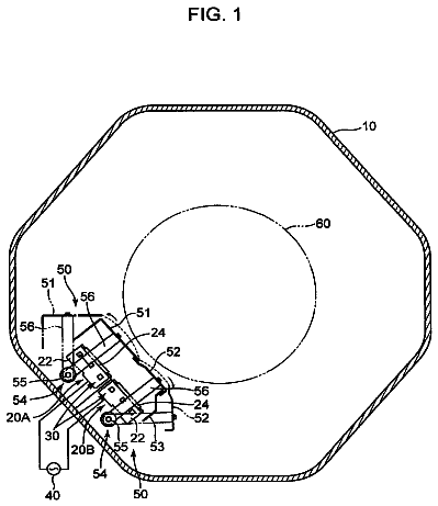
FIG. 4 is a perspective view showing the card conveying mechanism 10 shown in FIG. 1 . FIG. 5 is a perspective view showing a state in which a side plate 28 is detached from the card conveying mechanism 10 shown in FIG. 4 and which is viewed from an opposite side. FIG. 6 is an explanatory side view showing a structure of a drawing and sending-out drive mechanism 23 and a turning mechanism 24 shown in FIG. 5 . FIG. 7 is an explanatory view showing a drawing and sending-out mechanism 22 and a part of the drawing and sending-out drive mechanism 23 shown in FIG. 5 . FIGS. 8(A) and 8(B) are explanatory views showing a turning operation of card holding parts 15 and 16 shown in FIG. 5 .
The card conveying mechanism 10 includes two card holding parts 15 and 16 where a card 2 is temporarily held in their insides, a carriage 17 on which the card holding parts 15 and 16 are mounted, a carriage moving mechanism 18 structured to linearly move the carriage 17 in a horizontal direction, two guide shafts 19 and 20 for guiding the carriage 17 in a moving direction of the carriage 17 , and support frames 21 which support both end sides of the guide shafts 19 and 20 . In this embodiment, the carriage 17 is moved in the right and left direction. In other words, the right and left direction (“X” direction) in this embodiment is a moving direction of the carriage 17 .
The card holding parts 15 and 16 include a drawing and sending-out mechanism 22 structured to draw in and send out a card 2 . In other words, the card holding parts 15 and 16 include the drawing and sending-out mechanism 22 for drawing a card 2 into insides of the card holding parts 15 and 16 and for sending out the card 2 from the insides of the card holding parts 15 and 16 . Further, the card conveying mechanism 10 includes a drawing and sending-out drive mechanism 23 structured to drive the drawing and sending-out mechanism 22 and a turning mechanism 24 structured to turn the card holding parts 15 and 16 with respect to the carriage 17 .
The support frame 21 includes two side plates 26 which are formed in a flat plate shape parallel to the “Y-Z” plane structured of the front and rear direction (“Y” direction) and the upper and lower direction (“Z” direction) and are separately disposed from each other with a predetermined space therebetween in the right and left direction, and two connecting plates 27 which connect lower end sides of the two side plates 26 with each other. The side plate 26 is formed in substantially a pentagonal shape. An upper end face and a lower end face of the side plate 26 are parallel to the “X-Y” plane structured of the right and left direction (“X” direction) and the front and rear direction (“Y” direction), and a rear end face of the side plate 26 is parallel to the “Z-X” plane structured of the upper and lower direction (“Z” direction) and the right and left direction (“X” direction). A lower end side portion of a front end face of the side plate 26 is parallel to the “Z-X” plane. An upper end side portion of the front end face of the side plate 26 is inclined toward a rear side as going to an upper side.
The guide shafts 19 and 20 are formed in a long and thin circular columnar shape. The guide shafts 19 and 20 are fixed and supported by two side plates 26 so that their axial directions and the right and left direction are coincided with each other. The guide shaft 19 is supported in portions of two side plates 26 on the upper end side and the rear end side. The guide shaft 20 is supported in portions of two side plates 26 on the lower end side and the front end side. The guide shaft 19 in this embodiment is a first guide shaft and the guide shaft 20 is a second guide shaft. Further, in this embodiment, the front and rear direction is a second direction perpendicular to the right and left direction which is a moving direction of the carriage 17 and the upper and lower direction. The guide shaft 19 is supported in a portion on one side in the second direction (specifically, a rear end portion of the support frame 21 ).
The carriage 17 includes two side plates 28 and 29 , which are formed in a flat plate shape parallel to the “Y-Z” plane and are separately disposed from each other with a predetermined space therebetween in the right and left direction, and four connecting shafts 30 connecting two side plates 28 and 29 with each other. The side plate 28 structures a right side face of the carriage 17 and the side plate 29 structures a left side face of the carriage 17 . The connecting shaft 30 is disposed so that its axial direction and the right and left direction are coincided with each other and both end sides of the connecting shaft 30 are fixed to the side plates 28 and 29 . The side plates 28 and 29 are formed with two through-holes penetrating in the right and left direction, and a guide bush 31 formed in a substantially cylindrical tube shape is attached to the through-hole. The guide shafts 19 and 20 are inserted on an inner peripheral side of the guide bush 31 .
The description continues in the full USPTO document.
 Lapsed, fee not paid3 drawings