 Lapsed, fee not paid12 drawings
Industrial Equipment · US 9,751,657 B2
Material handling pallet
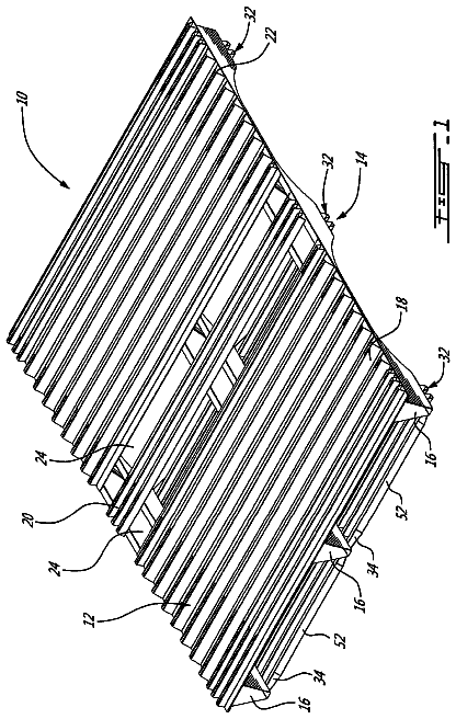
A metal pallet ( 10 ) has a deck ( 12 ), a base ( 14 ) and a plurality of beams ( 16 ) therebetween.
US 9,751,679 B2 · Assignee: Amcor Limited · Inventors: Stelzer; James et al.
Sheet 1 of 26 from the published document. All sheets in the USPTO PDF
A polymeric container including an upper portion defining an opening to an interior volume of the container. A base is movable to accommodate vacuum forces generated within the container, thereby decreasing the volume of the container. A substantially cylindrical sidewall extends between the upper portion and the base. A rigid, central pushup portion of the base is at an axial center of the base. A central longitudinal axis of the container extends through a center of the central pushup portion. A flexible diaphragm of the base extends outward from the central pushup portion.
This section provides background information related to the present disclosure, which is not necessarily prior art. This section also provides a general summary of the disclosure, and is not a comprehensive disclosure of its full scope or all of its features. As a result of environmental and other concerns, plastic containers, more specifically polyester and even more specifically polyethylene terephthalate (PET) containers, are now being used more than ever to package numerous commodities previously packaged in glass containers. Manufacturers and fillers, as well as consumers, have recognized that PET containers are lightweight, inexpensive, recyclable and manufacturable in large quantities. Manufacturers currently supply PET containers for various liquid commodities, such as juice and isotonic beverages. Suppliers often fill these liquid products into the containers while the liquid pr
1 of 26 drawing sheets so far from the published document, cropped to the drawing. Every sheet is in the USPTO PDF.
What the patent claimed, word for word. All of it is now free to use.
The present disclosure relates to vacuum absorbing bases for hot-fill containers.
This section provides background information related to the present disclosure, which is not necessarily prior art. This section also provides a general summary of the disclosure, and is not a comprehensive disclosure of its full scope or all of its features.
As a result of environmental and other concerns, plastic containers, more specifically polyester and even more specifically polyethylene terephthalate (PET) containers, are now being used more than ever to package numerous commodities previously packaged in glass containers. Manufacturers and fillers, as well as consumers, have recognized that PET containers are lightweight, inexpensive, recyclable and manufacturable in large quantities.
Manufacturers currently supply PET containers for various liquid commodities, such as juice and isotonic beverages. Suppliers often fill these liquid products into the containers while the liquid product is at an elevated temperature, typically between 68° C.-96° C. (155° F.-205° F.) and usually at approximately 85° C. (185° F.). When packaged in this manner, the hot temperature of the liquid commodity sterilizes the container at the time of filling. The bottling industry refers to this process as hot filling, and containers designed to withstand the process as hot-fill or heat-set containers.
The hot filling process is acceptable for commodities having a high acid content, but not generally acceptable for non-high acid content commodities. Nonetheless, manufacturers and fillers of non-high acid content commodities desire to supply their commodities in PET containers as well.
For non-high acid commodities, pasteurization and retort are the preferred sterilization process. Pasteurization and retort both present an enormous challenge for manufactures of PET containers in that heat-set containers cannot withstand the temperature and time demands required of pasteurization and retort.
Pasteurization and retort are both processes for cooking or sterilizing the contents of a container after filling. Both processes include the heating of the contents of the container to a specified temperature, usually above approximately 70° C. (approximately 155° F.), for a specified length of time (20-60 minutes). Retort differs from pasteurization in that retort uses higher temperatures to sterilize the container and cook its contents. Retort also applies elevated air pressure externally to the container to counteract pressure inside the container. The pressure applied externally to the container is necessary because a hot water bath is often used and the overpressure keeps the water, as well as the liquid in the contents of the container, in liquid form, above their respective boiling point temperatures.
PET is a crystallizable polymer, meaning that it is available in an amorphous form or a semi-crystalline form. The ability of a PET container to maintain its material integrity relates to the percentage of the PET container in crystalline form, also known as the “crystallinity” of the PET container. The following equation defines the percentage of crystallinity as a volume fraction:
% Crystallinity = ρ - ρ α ρ c - ρ α × 100 where ρ is the density of the PET material; ρ.sub.αis the density of pure amorphous PET material (1.333 g/cc); and ρ.sub.c is the density of pure crystalline material (1.455 g/cc).
Container manufactures use mechanical processing and thermal processing to increase the PET polymer crystallinity of a container. Mechanical processing involves orienting the amorphous material to achieve strain hardening. This processing commonly involves stretching a PET preform along a longitudinal axis and expanding the PET preform along a transverse or radial axis to form a PET container. The combination promotes what manufacturers define as biaxial orientation of the molecular structure in the container. Manufacturers of PET containers currently use mechanical processing to produce PET containers having approximately 20% crystallinity in the container's sidewall.
Thermal processing involves heating the material (either amorphous or semi-crystalline) to promote crystal growth. On amorphous material, thermal processing of PET material results in a spherulitic morphology that interferes with the transmission of light. In other words, the resulting crystalline material is opaque, and thus, generally undesirable. Used after mechanical processing, however, thermal processing results in higher crystallinity and excellent clarity for those portions of the container having biaxial molecular orientation. The thermal processing of an oriented PET container, which is known as heat setting, typically includes blow molding a PET preform against a mold heated to a temperature of approximately 120° C.-130° C. (approximately 248° F.-266° F.), and holding the blown container against the heated mold for approximately three
seconds. Manufacturers of PET juice bottles, which must be hot-filled at approximately 85° C. (185° F.), currently use heat setting to produce PET bottles having an overall crystallinity in the range of approximately 25-35%.
After being hot-filled, the heat-set containers are capped and allowed to reside at generally the filling temperature for approximately five
minutes at which point the container, along with the product, is then actively cooled prior to transferring to labeling, packaging, and shipping operations. The cooling reduces the volume of the liquid in the container. This product shrinkage phenomenon results in the creation of a vacuum within the container. Generally, vacuum pressures within the container range from 1-300 mm Hg less than atmospheric pressure (i.e., 759 mm Hg-460 mm Hg). If not controlled or otherwise accommodated, these vacuum pressures result in deformation of the container, which leads to either an aesthetically unacceptable container or one that is unstable.
In many instances, container weight is correlated to the amount of the final vacuum present in the container after this fill, cap and cool down procedure, that is, the container is made relatively heavy to accommodate vacuum related forces. Similarly, reducing container weight, i.e., “lightweighting” the container, while providing a significant cost savings from a material standpoint, requires a reduction in the amount of the final vacuum. Typically, the amount of the final vacuum can be reduced through various processing options such as the use of nitrogen dosing technology, minimize headspace or reduce fill temperature. One drawback with the use of nitrogen dosing technology however is that the maximum line speeds achievable with the current technology is limited to roughly 200 containers per minute. Such slower line speeds are seldom acceptable. Additionally, the dosing consistency is not yet at a technological level to achieve efficient operations. Minimizing headspace requires more precession during filling, again resulting in slower line speeds. Reducing fill temperature is equally disadvantageous as it limits the type of commodity suitable for the container.
Typically, container manufacturers accommodate vacuum pressures by incorporating structures in the container sidewall. Container manufacturers commonly refer to these structures as vacuum panels. Traditionally, these paneled areas have been semi-rigid by design, unable to accommodate the high levels of vacuum pressures currently generated, particularly in lightweight containers.
Development of technology options to achieve an ideal balance of light-weighting and design flexibility are of great interest. According to the principles of the present teachings, an alternative vacuum absorbing capability is provided within both the container body and base. Traditional hot-fill containers accommodate nearly all vacuum forces within the body (or sidewall) of the container through deflection of the vacuum panels. These containers are typically provided with a rigid base structure that substantially prevents deflection thereof and thus tends to be heavier than the rest of the container.
In contrast, POWERFLEX technology, offered by the assignee of the present application, utilizes a lightweight base design to accommodate nearly all vacuum forces. However, in order to accommodate such a large amount of vacuum, the POWERFLEX base must be designed to invert, which requires a dramatic snap-through from an outwardly curved initial shape to an inwardly curved final shape. This typically requires that the sidewall of the container be sufficiently rigid to allow the base to activate under vacuum, thus requiring more weight and/or structure within the container sidewall. Neither the traditional technology nor POWERFLEX system offers the optimal balance of a thin light-weight container body and base that is capable of withstanding the necessary vacuum pressures.
Therefore, an object of the present teachings is to achieve the optimal balance of weight and vacuum performance of both the container body and base. To achieve this, in some embodiments, a hot-fill container is provided that comprises a lightweight, flexible base design that is easily moveable to accommodate vacuum, but does not require a dramatic inversion or snap-through, thus eliminating the need for a heavy sidewall. The flexible base design serves to complement vacuum absorbing capabilities within the container sidewall. Furthermore, an object of the present teachings is to define theoretical light weighting limits and explore alternative vacuum absorbing technologies that create additional structure under vacuum.
The container body and base of the present teachings can each be lightweight structures designed to accommodate vacuum forces either simultaneously or in sequence. In any event, the goal is for both the container body and base to absorb a significant percentage of the vacuum. By utilizing a lightweight base design to absorb a portion of the vacuum forces enables an overall light-weighting, design flexibility, and effective utilization of alternative vacuum absorbing capabilities on the container sidewall. It is therefore an object of the present teachings to provide such a container. It should be understood, however, that in some embodiments some principles of the present teachings, such as the base configurations, can be used separate from other principles, such as the sidewall configurations, or vice versa.
The present teachings provide for a plastic container including an upper portion, a base, a plurality of surface features, and a substantially cylindrical portion. The upper portion has a mouth defining an opening into the container. The base is movable to accommodate vacuum forces generated within the container thereby decreasing the volume of the container. The plurality of surface features are included with the base and are configured to accommodate vacuum forces. The substantially cylindrical portion extends between the upper portion and the base.
The present teachings further provide for a plastic container including an upper portion, a base, a plurality of adjacent equilateral triangular features, and a substantially cylindrical portion. The base is movable to accommodate vacuum forces generated within the container thereby decreasing the volume of the container. The plurality of adjacent triangular features protrude from the base and are configured to accommodate vacuum forces. The substantially cylindrical portion extends between the upper portion and the base.
The present teachings also provide for a plastic container including an upper portion, a base, a plurality of adjacent equilateral triangular features, and a substantially cylindrical portion. The upper portion has a mouth defining an opening into the container. The base is movable to accommodate vacuum forces generated within the container thereby decreasing the volume of the container. The plurality of adjacent equilateral triangular features protrude from about 50% of the base and are configured to accommodate vacuum forces. The triangular features are spaced apart from both a central pushup of the base and a wall of the base. The substantially cylindrical portion extends between the upper portion and the base. The triangular features are formed from a mold including a plurality of peaks and troughs corresponding to the equilateral triangular features. The peaks are aligned along a first plane and the troughs are aligned along a second plane extending parallel to the first plane.
The present teachings further provide for a polymeric container including an upper portion defining an opening to an interior volume of the container. A base is movable to accommodate vacuum forces generated within the container, thereby decreasing the volume of the container. A substantially cylindrical sidewall extends between the upper portion and the base. A rigid, central pushup portion of the base is at an axial center of the base. A central longitudinal axis of the container extends through a center of the central pushup portion. A flexible diaphragm of the base extends outward from the central pushup portion.
Further areas of applicability will become apparent from the description provided herein. The description and specific examples in this summary are intended for purposes of illustration only and are not intended to limit the scope of the present disclosure.
The drawings described herein are for illustrative purposes only of selected embodiments and not all possible implementations, and are not intended to limit the scope of the present disclosure.
FIG. 1 is an elevational view of a plastic container according to the present teachings, the container as molded and empty.
FIG. 2 is an elevational view of the plastic container according to the present teachings, the container being filled and sealed.
FIG. 3 is a bottom perspective view of a portion of the plastic container of FIG. 1 .
FIG. 4 is a bottom perspective view of a portion of the plastic container of FIG. 2 .
FIG. 5 is a cross-sectional view of the plastic container, taken generally along line 5 - 5 of FIG. 3 .
FIG. 6 is a cross-sectional view of the plastic container, taken generally along line 6 - 6 of FIG. 4 .
FIG. 7 is a cross-sectional view of the plastic container, similar to FIG. 5 , according to some embodiments of the present teachings.
FIG. 8 is a cross-sectional view of the plastic container, similar to FIG. 6 , according to some embodiments of the present teachings.
FIG. 9 is a bottom view of an additional embodiment of the plastic container, the container as molded and empty.
FIG. 10 is a cross-sectional view of the plastic container, taken generally along line 10 - 10 of FIG. 9 .
FIG. 11 is a bottom view of the embodiment of the plastic container shown in FIG. 9 , the plastic container being filled and sealed.
FIG. 12 is a cross-sectional view of the plastic container, taken generally along line 12 - 12 of FIG. 11 .
FIG. 13 is a cross-sectional view of the plastic container, similar to FIGS. 5 and 7 , according to some embodiments of the present teachings.
FIG. 14 is a cross-sectional view of the plastic container, similar to FIGS. 6 and 8 , according to some embodiments of the present teachings.
FIG. 15 is a bottom view of the plastic container according to some embodiments of the present teachings.
FIG. 16 is a cross-sectional view of the plastic container, similar to FIGS. 5 and 7 , according to some embodiments of the present teachings.
FIG. 17 is a cross-sectional view of the plastic container, similar to FIGS. 6 and 8 , according to some embodiments of the present teachings.
FIG. 18 is a bottom view of the plastic container according to some embodiments of the present teachings.
FIG. 19 is a bottom view of the plastic container according to some embodiments of the present teachings.
FIG. 20 is a cross-sectional view of the plastic container of FIG. 19 .
FIG. 21 is a bottom view of the plastic container according to some embodiments of the present teachings.
FIG. 22 is a cross-sectional view of the plastic container of FIG. 21 .
FIG. 23 is an enlarged bottom view of the plastic container of FIG. 21 .
FIG. 24 is a bottom view of the plastic container according to some embodiments of the present teachings.
FIG. 25 is a cross-sectional view of the plastic container of FIG. 24 .
FIG. 26 is a bottom view of the plastic container according to some embodiments of the present teachings.
FIG. 27 is a cross-sectional view of the plastic container of FIG. 26 .
FIG. 28 is a graph illustrating the vacuum response versus displacement for the plastic container of FIG. 19 .
FIG. 29 is a graph illustrating the vacuum response versus displacement for the plastic container of FIG. 1 .
FIG. 30 is a graph illustrating the vacuum response versus displacement for the plastic container of FIG. 8 .
FIG. 31 is a cross-sectional view of a plastic container according to some embodiments of the present teachings.
FIG. 32 is a cross-sectional view of a plastic container according to some embodiments of the present teachings.
FIG. 33 is a bottom view of the plastic container according to some embodiments of the present teachings.
FIG. 34 is a cross-sectional view of the plastic container of FIG. 33 taken along line P.sub.L-P.sub.L of FIG. 33 .
FIG. 35 illustrates an exemplary triangular feature of an inversion ring of the plastic container of FIG. 33 .
FIG. 36 is a cross-sectional view of a mold for forming the plastic container of FIG. 33 .
FIG. 37 is an exterior plan view of another base according to the present teachings for a plastic container, such as the plastic container illustrated in FIG. 1 .
FIG. 38 is a cross-sectional view of the base of FIG. 37 in an as-blown position, the cross-sectional view taken along line 38 - 38 of FIG. 37 .
FIG. 39 is a perspective view of the base of FIG. 37 .
FIG. 40 is an exterior plan view of another base according to the present teachings for a plastic container, such as the plastic container of FIG. 1 .
FIG. 41 is a perspective view of the base of FIG. 40 .
Corresponding reference numerals indicate corresponding parts throughout the several views of the drawings.
Example embodiments will now be described more fully with reference to the accompanying drawings. Example embodiments are provided so that this disclosure will be thorough, and will fully convey the scope to those who are skilled in the art. Numerous specific details are set forth such as examples of specific components, devices, and methods, to provide a thorough understanding of embodiments of the present disclosure. It will be apparent to those skilled in the art that specific details need not be employed, that example embodiments may be embodied in many different forms and that neither should be construed to limit the scope of the disclosure.
The terminology used herein is for the purpose of describing particular example embodiments only and is not intended to be limiting. As used herein, the singular forms “a”, “an” and “the” may be intended to include the plural forms as well, unless the context clearly indicates otherwise. The terms “comprises,” “comprising,” “including,” and “having,” are inclusive and therefore specify the presence of stated features, integers, steps, operations, elements, and/or components, but do not preclude the presence or addition of one or more other features, integers, steps, operations, elements, components, and/or groups thereof. The method steps, processes, and operations described herein are not to be construed as necessarily requiring their performance in the particular order discussed or illustrated, unless specifically identified as an order of performance. It is also to be understood that additional or alternative steps may be employed.
As discussed above, to accommodate vacuum forces during cooling of the contents within a heat-set container, containers generally have a series of vacuum panels or ribs around their sidewall. Traditionally, these vacuum panels have been semi-rigid and incapable of preventing unwanted distortion elsewhere in the container, particularly in lightweight containers. However, in some vacuum panel-less containers, a combination of controlled deformation (i.e., in the base or closure) and vacuum resistance in the remainder of the container is required. As discussed herein, each of the above examples (i.e. traditional vacuum absorbing container having a lightweight and flexible sidewall with a heavy and rigid base, and POWERFLEX container having a lightweight and flexible base with a heavy and rigid sidewall) may not fully optimize a hot-fill container design. Moreover, the simple combination of the sidewall of the traditional vacuum absorbing container and the base of the POWERFLEX container would typically lead to a container having a sidewall that is not sufficiently rigid to withstand the snap-through from an outwardly curved initial shape to an inwardly curved final shape.
Accordingly, the present teachings provide a plastic container which enables its base portion under typical hot-fill process conditions to deform and move easily while maintaining a rigid structure (i.e., against internal vacuum) in the remainder of the container. As an example, in a 16 fl. oz. plastic container, the container typically should accommodate roughly 18-24 cc of volume displacement. In the present plastic container, the base portion accommodates a majority of this requirement. The remaining portions of the plastic container are easily able to accommodate the rest of this volume displacement without readily noticeable distortion. More particularly, traditional containers utilize a combination of bottle geometry and wall thickness to create a structure that can resist a portion of the vacuum, and movable sidewall panels, collapsible ribs, or moveable bases to absorb the remaining vacuum. This results in two elements of internal vacuum—residual and absorbed. The sum of the residual vacuum and the absorbed vacuum equals the total amount of vacuum that results from the combination of the liquid commodity and the headspace contracting during cooling in a rigid container.
Although alternative designs are available in the art, including those requiring the use of external activation devices on the filling line (as in the Graham ATP technology), the present teachings are able to achieve lighter hot fillable containers, without requiring an external activation device, by absorbing a higher percentage of the internal vacuum and/or volume in a controlled way while simultaneously providing sufficient structural integrity to maintain the desired bottle shape.
In some embodiments, the container according to the present teachings combines sidewall vacuum and/or volume compensation panels or collapsible ribs with a flexible base design resulting in a hybrid of previous technologies that results in a lighter weight container than could be achieved with either method individually.
The vacuum and/or volume compensation characteristics could be defined as:
X=the percentage of the total vacuum and/or volume that is absorbed by the sidewall panels, ribs and/or other vacuum and/or volume compensation features;
Y=the percentage of the total vacuum and/or volume that is absorbed by the base movement; and
Z=the residual vacuum and/or volume remaining in the container after the compensation achieved by the vacuum and/or volume compensation features in the sidewall and/or base.
In the case of the traditional vacuum compensation features (i.e. sidewall only or base only), the vacuum and/or volume compensation could be expressed as:
Z=10 to 90% of the total vacuum and/or volume; and
X OR Y=10 to 90% of the total vacuum and/or volume.
It should be appreciated from the foregoing that a conventional container could merely achieve a total of 90% of the total vacuum and/or volume.
However, according to the present teachings, a hot-fillable container is provided where the vacuum and/or volume compensation could be described as:
Z=0 to 25% of the total vacuum and/or volume;
X=10 to 90% of the total vacuum and/or volume; and
Y=10 to 90% of the total vacuum and/or volume.
As can be seen, according to these principles, the present teachings are operable to achieve vacuum absorption in both the base and the sidewall, thereby permitting, if desired, absorption of the entire internal vacuum. It should be appreciated that in some embodiments a slight remaining vacuum may be desired.
To accomplish the lightest possible container weight with respect to vacuum, the residual vacuum (Z) should be as close as possible to 0% of the total vacuum and the combined movements of the vacuum absorbing features would be designed to absorb basically 100% of the volume contraction that occurs inside of the container as the contents cool from the filling temperature to the point of maximum density under the required service conditions. At this point external forces such as top load or side load would result in a pressurization of the container that would help it to resist those external forces. This would result in a container weight that is dictated by the requirements of the handling and distribution system, not by the filling conditions.
In some embodiments, the present teachings provide a significantly round plastic container that does not ovalize below 5% total vacuum absorption that consists of a movable base and a movable sidewall at an average wall thickness less than 0.020″. However, in some embodiments, the present teachings can provide a plastic container that comprises a base that absorbs between 10 and 90% of the total vacuum in conjunction with a sidewall that absorbs between 90 and 10% of the total vacuum absorbed. In some embodiments, the base and the sidewall can activate simultaneously. However, in some embodiments, the base and the sidewall can activate sequentially.
Still further, according to the present teachings, a significantly round plastic container is provided that provides a movable base and a movable sidewall that both activate simultaneously or sequentially at a vacuum level less than that of 5% of the total vacuum absorption of the container.
In a vacuum panel-less container, a combination of controlled deformation (i.e., in the base or closure) and vacuum resistance in the remainder of the container is required. Accordingly, the present teaching provides for a plastic container which enables its base portion under typical hot-fill process conditions to deform and move easily while maintaining a rigid structure (i.e., against internal vacuum) in the remainder of the container.
As shown in FIGS. 1 and 2 , a plastic container 10 of the invention includes a finish 12 , a neck or an elongated neck 14 , a shoulder region 16 , a body portion 18 , and a base 20 . Those skilled in the art know and understand that the neck 14 can have an extremely short height, that is, becoming a short extension from the finish 12 , or an elongated neck as illustrated in the figures, extending between the finish 12 and the shoulder region 16 . The plastic container 10 has been designed to retain a commodity during a thermal process, typically a hot-fill process. For hot-fill bottling applications, bottlers generally fill the container 10 with a liquid or product at an elevated temperature between approximately 155° F. to 205° F. (approximately 68° C. to 96° C.) and seal the container 10 with a closure 28 before cooling. As the sealed container 10 cools, a slight vacuum, or negative pressure, forms inside causing the container 10 , in particular, the base 20 to change shape. In addition, the plastic container 10 may be suitable for other high-temperature pasteurization or retort filling processes, or other thermal processes as well.
The plastic container 10 of the present teaching is a blow molded, biaxially oriented container with a unitary construction from a single or multi-layer material. A well-known stretch-molding, heat-setting process for making the hot-fillable plastic container 10 generally involves the manufacture of a preform (not illustrated) of a polyester material, such as polyethylene terephthalate (PET), having a shape well known to those skilled in the art similar to a test-tube with a generally cylindrical cross section and a length typically approximately fifty percent (50%) that of the container height. A machine (not illustrated) places the preform heated to a temperature between approximately 190° F. to 250° F. (approximately 88° C. to 121° C.) into a mold cavity (not illustrated) having a shape similar to the plastic container 10 . The mold cavity is heated to a temperature between approximately 250° F. to 350° F. (approximately 121° C. to 177° C.). A stretch rod apparatus (not illustrated) stretches or extends the heated preform within the mold cavity to a length approximately that of the container thereby molecularly orienting the polyester material in an axial direction generally corresponding with a central longitudinal axis 50 . While the stretch rod extends the preform, air having a pressure between 300 PSI to 600 PSI (2.07 MPa to 4.14 MPa) assists in extending the preform in the axial direction and in expanding the preform in a circumferential or hoop direction thereby substantially conforming the polyester material to the shape of the mold cavity and further molecularly orienting the polyester material in a direction generally perpendicular to the axial direction, thus establishing the biaxial molecular orientation of the polyester material in most of the container. Typically, material within the finish 12 and a sub-portion of the base 20 are not substantially molecularly oriented. The pressurized air holds the mostly biaxial molecularly oriented polyester material against the mold cavity for a period of approximately two
to five
seconds before removal of the container from the mold cavity. To achieve appropriate material distribution within the base 20 , the inventors employ an additional stretch-molding step substantially as taught by U.S. Pat. No. 6,277,321 which is incorporated herein by reference.
Alternatively, other manufacturing methods using other conventional materials including, for example, high density polyethylene, polypropylene, polyethylene naphthalate (PEN), a PET/PEN blend or copolymer, and various multilayer structures may be suitable for the manufacture of plastic container 10 . Those having ordinary skill in the art will readily know and understand plastic container 10 manufacturing method alternatives.
The finish 12 of the plastic container 10 includes a portion defining an aperture or mouth 22 , a threaded region 24 , and a support ring 26 . The aperture 22 allows the plastic container 10 to receive a commodity while the threaded region 24 provides a means for attachment of the similarly threaded closure or cap 28 (shown in FIG. 2 ). Alternatives may include other suitable devices that engage the finish 12 of the plastic container 10 . Accordingly, the closure or cap 28 engages the finish 12 to preferably provide a hermetical seal of the plastic container 10 . The closure or cap 28 is preferably of a plastic or metal material conventional to the closure industry and suitable for subsequent thermal processing, including high temperature pasteurization and retort. The support ring 26 may be used to carry or orient the preform (the precursor to the plastic container 10 ) (not shown) through and at various stages of manufacture. For example, the preform may be carried by the support ring 26 , the support ring 26 may be used to aid in positioning the preform in the mold, or an end consumer may use the support ring 26 to carry the plastic container 10 once manufactured.
The elongated neck 14 of the plastic container 10 in part enables the plastic container 10 to accommodate volume requirements. Integrally formed with the elongated neck 14 and extending downward therefrom is the shoulder region 16 . The shoulder region 16 merges into and provides a transition between the elongated neck 14 and the body portion 18 . The body portion 18 extends downward from the shoulder region 16 to the base 20 and includes sidewalls 30 . The specific construction of the base 20 of the container 10 allows the sidewalls 30 for the heat-set container 10 to not necessarily require additional vacuum panels or pinch grips and therefore, can be generally smooth and glass-like. However, a significantly lightweight container will likely include sidewalls having vacuum panels, ribbing, and/or pinch grips along with the base 20 .
The base 20 of the plastic container 10 , which extends inward from the body portion 18 , can comprise a chime 32 , a contact ring 34 and a central portion 36 . In some embodiments, the contact ring 34 is itself that portion of the base 20 that contacts a support surface 38 that in turn supports the container 10 . As such, the contact ring 34 may be a flat surface or a line of contact generally circumscribing, continuously or intermittently, the base 20 . The base 20 functions to close off the bottom portion of the plastic container 10 and, together with the elongated neck 14 , the shoulder region 16 , and the body portion 18 , to retain the commodity.
In some embodiments, the plastic container 10 is preferably heat-set according to the above-mentioned process or other conventional heat-set processes. In some embodiments, to accommodate vacuum forces while allowing for the omission of vacuum panels and pinch grips in the body portion 18 of the container 10 , the base 20 of the present teaching adopts a novel and innovative construction. Generally, the central portion 36 of the base 20 can comprise a central pushup 40 and an inversion ring 42 . The inversion ring 42 can include an upper portion 54 and a lower portion 58 . Additionally, the base 20 can include an upstanding circumferential wall or edge 44 that forms a transition between the inversion ring 42 and the contact ring 34 .
As shown in the figures, the central pushup 40 , when viewed in cross section, is generally in the shape of a truncated cone having a top surface 46 that is generally parallel to the support surface 38 . Side surfaces 48 , which are generally planar in cross section, slope upward toward the central longitudinal axis 50 of the container 10 . The exact shape of the central pushup 40 can vary greatly depending on various design criteria. However, in general, the overall diameter of the central pushup 40 (that is, the truncated cone) is at most 30% of generally the overall diameter of the base 20 . The central pushup 40 is generally where the preform gate is captured in the mold. Located within the top surface 46 is the sub-portion of the base 20 which includes polymer material that is not substantially molecularly oriented.
In some embodiments as shown in FIGS. 3, 5, 7, 10, 13 and 16 , when initially formed, the inversion ring 42 , having a gradual radius, completely surrounds and circumscribes the central pushup 40 . As formed, the inversion ring 42 can protrude outwardly, below a plane where the base 20 would lie if it was flat. The transition between the central pushup 40 and the adjacent inversion ring 42 can be rapid in order to promote as much orientation as near the central pushup 40 as possible. This serves primarily to ensure a minimal wall thickness 66 for the inversion ring 42 , in particular at the lower portion 58 of the base 20 . In some embodiments, the wall thickness 66 of the lower portion 58 of the inversion ring 42 is between approximately 0.008 inch (0.20 mm) to approximately 0.025 inch (0.64 mm), and preferably between approximately 0.010 inch to approximately 0.014 inch (0.25 mm to 0.36 mm) for a container having, for example, an approximately 2.64-inch (67.06 mm) diameter base. Wall thickness 70 of top surface 46 , depending on precisely where one takes a measurement, can be 0.060 inch (1.52 mm) or more; however, wall thickness 70 of the top surface 46 quickly transitions to wall thickness 66 of the lower portion 58 of the inversion ring 42 . The wall thickness 66 of the inversion ring 42 must be relatively consistent and thin enough to allow the inversion ring 42 to be flexible and function properly. At a point along its circumventional shape, the inversion ring 42 may alternatively feature a small indentation, not illustrated but well known in the art, suitable for receiving a pawl that facilitates container rotation about the central longitudinal axis 50 during a labeling operation.
The circumferential wall or edge 44 , defining the transition between the contact ring 34 and the inversion ring 42 can be, in cross section, an upstanding substantially straight wall approximately 0.030 inch (0.76 mm) to approximately 0.325 inch (8.26 mm) in length. Preferably, for a 2.64-inch (67.06 mm) diameter base container, the circumferential wall 44 can measure between approximately 0.140 inch to approximately 0.145 inch (3.56 mm to 3.68 mm) in length. For a 5-inch (127 mm) diameter base container, the circumferential wall 44 could be as large as 0.325 inch (8.26 mm) in length. The circumferential wall or edge 44 can be generally at an angle 64 relative to the central longitudinal axis 50 of between approximately zero degree and approximately 20 degrees, and preferably approximately 15 degrees. Accordingly, the circumferential wall or edge 44 need not be exactly parallel to the central longitudinal axis 50 . The circumferential wall or edge 44 is a distinctly identifiable structure between the contact ring 34 and the inversion ring 42 . The circumferential wall or edge 44 provides strength to the transition between the contact ring 34 and the inversion ring 42 . In some embodiments, this transition must be abrupt in order to maximize the local strength as well as to form a geometrically rigid structure. The resulting localized strength increases the resistance to creasing in the base 20 . The contact ring 34 , for a 2.64-inch (67.06 mm) diameter base container, can have a wall thickness 68 of approximately 0.010 inch to approximately 0.016 inch (0.25 mm to 0.41 mm). In some embodiments, the wall thickness 68 is at least equal to, and more preferably is approximately ten percent, or more, than that of the wall thickness 66 of the lower portion 58 of the inversion ring 42 .
The description continues in the full USPTO document.
About 6,120 words. The USPTO PDF has it with every drawing.
Fees are due 3.5, 7.5 and 11.5 years after grant. This patent expired on September 5, 2025, so the fee marked "not paid" was the one that went unpaid.
Vacuum Absorbing Bases for Hot-Fill Containers
Filed Jun 2016 · published Oct 2016Vacuum absorbing bases for hot-fill containers
Filed Jun 2016 · granted Sep 2017Earlier publications, parents and continuations. None of them can still be enforced, or this patent would not be listed.
Prior art cited by the examiner or applicant. Useful when you check your own idea for novelty.
Everything on this page comes from the documents linked above.