Technical field
The present invention relates to a brake device for a vehicle, including a master cylinder for generating a hydraulic pressure in response to an operation by a driver on a brake pedal, a power hydraulic pressure source for generating a hydraulic pressure through drive of a pressure pump, a valve mechanism including a plurality of electromagnetic valves to be controlled by electric signals, for carrying out transmission of the hydraulic pressure output from the master cylinder or the power hydraulic pressure source, a wheel cylinder for applying a braking force to a wheel through the transmission of the hydraulic pressure output from the master cylinder or the power hydraulic pressure source via the valve mechanism, and control means for controlling an operation of the valve mechanism.
Background art
In recent years, there has been proposed a brake device configured to selectively use a hydraulic pressure from a master cylinder and a hydraulic pressure from a pressure pump (accumulator), which is a power hydraulic pressure source. For example, a brake system disclosed in Patent Literature 1 and a brake control device disclosed in Patent Literature 2 have hitherto been known as the brake device of this type. In the brake system and the brake control device, a target hydraulic pressure for each wheel cylinder is set so as to correspond to the hydraulic pressure generated in the master cylinder by a depressing operation by the driver on the brake pedal, and the hydraulic pressure pressurized by the pressure pump is controlled to follow the target hydraulic pressure and to be supplied by driving a linear control valve and various electromagnetic on-off valves. Further, for example, the following technology has been proposed. As in the brake control device disclosed in Patent Literature 2, only a pressure increasing linear control valve for realizing pressure increasing linear control is provided between the power hydraulic pressure source and a main flow passage to which the plurality of wheel cylinders are connected in order to control, in common, hydraulic pressures in the plurality of wheel cylinders. Pressure reducing linear control valves are employed as a part of pressure reducing valves, which are provided on the respective wheels and communicable to a reservoir. In this manner, the number of valves provided for the entire brake device is decreased. CITATION LIST Patent Literature
[ptl 1]
Jp 2011-156998 a
[ptl 2]
Jp 2008-290487 a summary of invention
In the above-mentioned technology, when the hydraulic pressures in the wheel cylinders are decreased, the pressure reducing valves including the pressure reducing linear control valves communicable to the reservoir are used. In this case, the brake device for a vehicle can be reduced in cost by replacing the expensive pressure reducing linear control valve by the simple electromagnetic on-off valve.
Incidentally, the related-art brake system and brake control device include, as the various electromagnetic on-off valves, for each of brake systems for the respective wheels, a holding valve for at least permitting or shutting off communication between an upstream side connected to the main flow passage to which the hydraulic pressure is transmitted from the power hydraulic pressure source and a downstream side connected to the wheel cylinder, and a pressure reducing valve for permitting or shutting off communication between the wheel cylinder and the reservoir. In the related-art brake system and brake control device, when the brake pedal on which the driver has carried out the depressing operation is operated toward a return direction of reducing the hydraulic pressure in the wheel cylinders, the hydraulic pressures in the wheel cylinders are decreased by opening the pressure reducing valves provided on the brake systems for the respective wheels. Moreover, in the related-art brake system and brake control device, the hydraulic pressure in the main flow passage is decreased via the pressure reducing valves provided on the brake systems for the respective wheels by opening the holding valves provided in the brake systems.
In this case, when the antiskid control is carried out in the related-art brake system and brake control device, the holding valve and the pressure reducing valve are independently controlled for operation in the brake system for the each wheel, and hence there may arise such a state that brake systems controlled to have high pressures and brake systems controlled to have low pressures exist. When the driver operates the brake pedal in the return direction in this state, and, for example, the holding valves provided on the brake systems controlled to have the low pressures are opened in order to decrease the hydraulic pressure in the main flow passage, the high hydraulic pressure may be transmitted from the main flow passage side, thereby influencing the hydraulic pressures in the wheel cylinders. As a result, the driver may feel a sense of discomfort in brake operation feeling.
The present invention has been made in view of the above-mentioned problem, and therefore has an object to provide a brake device for a vehicle configured to generate appropriate braking forces, thereby providing satisfactory brake operation feeling even when a brake pedal is operated toward a return direction during antiskid control.
In order to achieve the object, the brake device for a vehicle according to one embodiment of the present invention includes a master cylinder, a power hydraulic pressure source, a valve mechanism, a wheel cylinder, and control means.
The master cylinder is configured to generate a hydraulic pressure in response to an operation by a driver on a brake pedal. The power hydraulic pressure source is configured to generate a hydraulic pressure through drive of a pressure pump. It should be noted that if the power hydraulic pressure source includes an accumulator, the hydraulic pressure generated by the pressure pump is accumulated in the accumulator. The valve mechanism includes a plurality of electromagnetic valves to be controlled by electric signals, and is configured to carry out transmission of the hydraulic pressure output from the master cylinder or the power hydraulic pressure source. The wheel cylinder is configured to apply a braking force to each of wheels through the transmission of the hydraulic pressure output from the master cylinder or the power hydraulic pressure source via the valve mechanism. The control means is configured to control the operation of the valve mechanism.
In this case, during an abnormal state in which there is a possibility of a leak of a working fluid in any of brake systems for transmitting the hydraulic pressure from the power hydraulic pressure source to the wheel cylinders provided on a front right wheel, a front left wheel, a rear right wheel, and a rear left wheel of a vehicle, the control means may control the holding valves to be in the open state so as to maintain the communication between the wheel cylinders provided on rear right and left wheel sides of the vehicle and the power hydraulic pressure source, and control the holding valves to be in the closed state so as to shut off the communication between the wheel cylinders provided on front right and left wheel sides of the vehicle and the power hydraulic pressure source and to transmit at least the hydraulic pressure from the master cylinder to the wheel cylinders provided on the front right and left wheel sides of the vehicle. Moreover, in this case, the brake device for a vehicle may further include a pressure increasing mechanism. The pressure increasing mechanism is connected to the master cylinder and the power hydraulic pressure source so as to generate a hydraulic pressure having a predetermined ratio with respect to the hydraulic pressure from the master cylinder by using the hydraulic pressure from the power hydraulic pressure source. In this case, the pressure increasing mechanism may be mechanically operated by the hydraulic pressure output from the master cylinder in response to, for example, the operation by the driver on the brake pedal.
The brake device for a vehicle according to one embodiment of the present invention has feature in that the valve mechanism includes: holding valves, which are each an electromagnetic on-off valve, provided for the respective wheels so as to realize at least communication or shutoff between an upstream side to which the hydraulic pressure is transmitted from the power hydraulic pressure source and a downstream side to which the wheel cylinder is connected; pressure reducing valves, which are each an electromagnetic on-off valve, provided in correspondence to the respective holding valves so as to realize at least communication or shutoff between the wheel cylinder and a reservoir; and a pressure increasing valve, which is an electromagnetic valve, for increasing the hydraulic pressure on the upstream side by using the hydraulic pressure from the power hydraulic pressure source. Further, the control means is configured to, during antiskid control for suppressing an excessive slip in a longitudinal direction of a wheel to which the braking force is applied, when the brake pedal subjected to a depressing operation is operated toward a return direction by the driver: inhibit, out of the holding valves provided for the respective wheels, inhibits the holding valve controlled to be in a closed state based on the antiskid control from shifting to an open state; and control the pressure reducing valve provided in correspondence to the holding valve in the open state based on the antiskid control to shift to an open state.
As a result, when the brake pedal subjected to the depressing operation is operated toward the return direction by the driver during the antiskid control, the holding valves in the closed state may be inhibited from shifting to the open state. As a result, the high hydraulic pressure is securely prevented from being transmitted to the wheel cylinders controlled to have low pressures by maintaining the holding valves in the closed state based on the antiskid control. Thus, the braking force applied by the wheel cylinder is securely prevented from fluctuating on the wheel for which the holding valve is controlled to be in the closed state, and the driver may gain satisfactory brake operation feeling.
On the other hand, when the brake pedal subjected to the depressing operation is operated toward the return direction by the driver during the antiskid control, the holding valves in the open state are still maintained in the open state, and the pressure reducing valves provided in correspondence with the holding valves are controlled to shift to the open state. As a result, the high hydraulic pressure on the upstream side of the holding valves is decreased via the holding valves and the pressure reducing valves in the open state. Thus, the high hydraulic pressure has already been transmitted to the wheel cylinder from the upstream side on the wheel on which the holding valve is maintained in the open state, and the hydraulic pressure on the upstream side of the holding valve and the hydraulic pressure in the wheel cylinder on the downstream side of the holding valve may be quickly decreased by controlling the corresponding pressure reducing valve to shift to the open state. As a result, the braking force applied by the wheel cylinder can be quickly released without a fluctuation in the braking force. Thus, the driver may gain satisfactory brake operation feeling.
In this case, when the control means controls all the holding valves to be in the closed state based on the antiskid control, the control means may cancel the inhibition of the shift to the open state in the holding valve provided for the wheel having the maximum hydraulic pressure in the wheel cylinder, and may control the corresponding holding valve to shift to the open state. More specifically, for example, the control means may estimate the hydraulic pressure in the wheel cylinder for each of a front right wheel, a front left wheel, a rear right wheel, and a rear left wheel of a vehicle, and select, based on the estimated hydraulic pressure, the holding valve provided for the wheel having the maximum hydraulic pressure in the wheel cylinder. It should be noted that, in this case, the control means may include hydraulic pressure estimation means for estimating the hydraulic pressure in the wheel cylinder for each of the front right wheel, the front left wheel, the rear right wheel, and the rear left wheel of the vehicle, and selection means for selecting, based on the hydraulic pressures estimated by the hydraulic pressure estimation means, the holding valve provided for the wheel having the maximum hydraulic pressure in the wheel cylinder.
As a result, even under a state in which the control means controls all the holding valves to be in the closed state based on the antiskid control, when the brake pedal subjected to the depressing operation is operated toward the return direction by the driver, the control means may select the holding valve provided for the wheel having the maximum hydraulic pressure in the wheel cylinder, and may cancel the inhibition of this holding valve from shifting to the open state, thereby controlling the holding valve to shift from the closed state to the open state. The control means may further control the pressure reducing valve provided in correspondence to this holding valve to shift to the open state. As a result, even under a state in which the high hydraulic pressure on the upstream side is to be transmitted, the increase in hydraulic pressure after the transmission is relatively small for the wheel cylinder having the maximum hydraulic pressure. Thus, even under a state in which all the holding valves are controlled to be in the closed state based on the antiskid control, when the brake pedal subjected to the depressing operation is operated toward the return direction by the driver, the fluctuation range of the braking force applied by the wheel cylinder may be suppressed to be small, and the driver may gain satisfactory brake operation feeling.
Moreover, in this case, it is preferred that the holding valve in the open state be, for example, the holding valve controlled to be in the open state for a predetermined period or more. In other words, if the period in which the holding valve is opened is shorter than the predetermined period, the hydraulic pressure on the upstream side may not be appropriately decreased due to an influence of a pressure loss (orifice). Thus, the predetermined period is set to such a period that the influence of the pressure loss (orifice) is no long exerted, and the holding valve controlled to be in the open state for the predetermined period or more may be determined to be the holding valve in the open state. A holding valve controlled to be in the open state only for a period less than the predetermined period may be determined not to be the holding valve in the open state.
As a result, the hydraulic pressures on the upstream side and on the downstream side approximately match each other on a wheel on which the holding valve determined to be in the open state in this way is provided, and the pressure can be appropriately decreased via the pressure reducing valve provided in correspondence without a fluctuation in the hydraulic pressure in the wheel cylinder. Thus, the braking force applied by the wheel cylinder can be quickly released without a fluctuation in the braking force. Thus, the driver may gain satisfactory brake operation feeling.
Brief description of drawings
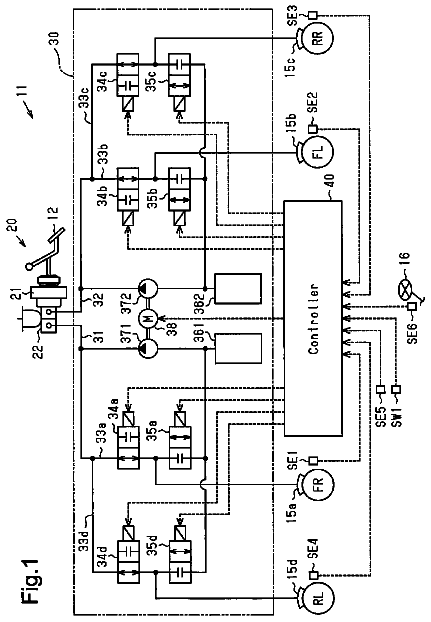
FIG. 1 is a schematic system diagram of a brake device for a vehicle according to an embodiment of the present invention.
FIG. 2 is a schematic cross sectional view illustrating a configuration of a pressure increasing mechanism of FIG. 1 .
FIG. 3 is a diagram illustrating a linear control mode by the brake device for a vehicle according to the embodiment of the present invention.
FIG. 4 is a diagram illustrating a backup mode by the brake device for a vehicle according to the embodiment of the present invention when a fluid leak occurs.
FIG. 5 is a diagram illustrating a return operation during antiskid control by the brake device for a vehicle according to the embodiment of the present invention.
FIG. 6 is a diagram illustrating the return operation during the antiskid control by the brake device for a vehicle according to a modified example of the present invention.
Description of embodiments
Now, a brake device for a vehicle according to an embodiment of the present invention is described referring to the drawings. FIG. 1 is a schematic system diagram of the brake device for a vehicle according to this embodiment.
The brake device for a vehicle includes a brake pedal 10 , a master cylinder unit 20 , a power hydraulic pressure generation device 30 , a hydraulic pressure control valve device 50 , a pressure increasing mechanism 80 , a pressure increasing mechanism cut valve 90 , and a brake ECU 100 for brake control. Brake units 40 FR, 40 FL, 40 RR, and 40 RL installed on respective wheels include brake rotors 41 FR, 41 FL, 41 RR, and 41 RL, and wheel cylinders 42 FR, 42 FL, 42 RR, and 42 RL integrated into brake calipers. In the following description, configurations provided for the respective wheels are denoted by suffixes FR for a front right wheel, FL for a front left wheel, RR for a rear right wheel, and RL for a rear left wheel, but if the specification of the wheel position is not particularly necessary, the suffix is omitted. The brake units 40 are not limited to the case where disk brakes are installed on all the four wheels, and, for example, drum brakes may be installed on all the four wheels, or the disk brakes and the drum brakes may be arbitrarily combined in such a way that the disk brakes are installed on the front wheels and the drum brakes are installed on the rear wheels.
The wheel cylinders 42 FR, 42 FL, 42 RR, and 42 RL are connected to the hydraulic pressure control valve device 50 , and receive transmitted hydraulic pressures of a working fluid (brake fluid) supplied from the hydraulic pressure control device 50 . Then, brake pads are pressed against the brake rotors 41 FR, 41 FL, 41 RR, and 41 RL rotating along with the wheels by the hydraulic pressure transmitted (supplied) from the hydraulic pressure control valve device 50 , thereby applying braking forces to the wheels.
The master cylinder unit 20 includes a master cylinder 21 and a reservoir 22 . The master cylinder 21 is of a tandem type including pressure pistons 21 a and 21 b , and generates master cylinder pressures Pmc_FR and Pmc_FL having respective predetermined boost ratios to a pedal depressing force input in response to an operation of depressing the brake pedal 10 by a driver. The reservoir 22 for storing the working fluid is provided at a top of the master cylinder 21 . As a result, when the driver's operation of depressing the brake pedal 10 is released and the pressure pistons 21 a and 21 b are retreated, in the master cylinder 21 , pressure chambers 21 a 1 and 21 b 1 formed by the pressure pistons 21 a and 21 b communicate to the reservoir 22 . It should be noted that the pressure chambers 21 a 1 and 21 b 1 respectively communicate to the hydraulic pressure control valve device 50 via master pressure pipes 11 and 12 described later.
The power hydraulic pressure generation device 30 is a power hydraulic pressure source (power supply), and includes a pressure pump 31 and an accumulator 32 . The pressure pump 31 has an inlet opening connected to the reservoir 22 and an outlet opening connected to the accumulator 32 , and pressurizes the working fluid through drive of a motor 33 . The accumulator 32 converts pressure energy of the working fluid pressurized by the pressure pump 31 into pressure energy of a filler gas such as nitrogen, thereby accumulating the pressure energy. Moreover, the accumulator 32 is connected to a relief valve 23 provided to the master cylinder unit 20 . The relief valve 23 opens when the pressure of the working fluid increases to a predetermined pressure or more, thereby returning the working fluid to the reservoir 22 .
In this way, the brake device for a vehicle includes, as the hydraulic pressure source for applying a hydraulic pressure of the working fluid to the wheel cylinders 42 , the master cylinder 21 for applying the hydraulic pressure by using the pedal depressing force input by the driver via the brake pedal 10 , and the power hydraulic pressure generation device 30 for applying the hydraulic pressure independently of the master cylinder 21 . Then, in the brake device for a vehicle, the master cylinder 21 (more specifically, pressure chambers 21 a 1 and 21 b 1 ) and the power hydraulic pressure generation device 30 are connected respectively to the hydraulic pressure control valve device 50 via the master pressure pipes 11 and 12 and an accumulator pressure pipe 13 . Moreover, the reservoir 22 is connected to the hydraulic pressure control valve device 50 via a reservoir pipe 14 . It should be noted that, hereinafter, regarding the master pressure pipe 12 , an upstream side (input side) with respect to the pressure increasing mechanism 80 is referred to as master pressure pipe 12 a , and a downstream side (output side) with respect to the pressure increasing mechanism 80 is referred to as master pressure pipe 12 b for discrimination.
On this occasion, a stroke simulator 70 is connected to the master pressure pipe 12 a via a simulator flow passage 71 and a simulator cut valve 72 , which is a normally-closed electromagnetic on-off valve. The stroke simulator 70 includes a piston 70 a and a spring 70 b , and introduces the working fluid having an amount corresponding to a brake operation amount of the brake pedal 10 by the driver into an inside when the simulator cut valve 72 is in the open state. Then, the stroke simulator 70 displaces the piston 70 a against a biasing force of the spring 70 b in synchronous with the introduction of the working fluid into the inside, thereby enabling a stroke operation of the brake pedal 10 by the driver, and generating a reaction force corresponding to the brake operation amount to provide satisfactory brake operation feeling to the driver. It should be understood that the stroke simulator 70 can be connected to the master pressure pipe 11 .
The hydraulic pressure control valve device 50 having a valve mechanism includes four individual flow passages 51 FR, 51 FL, 51 RR, and 51 RL connected to the respective wheel cylinders 42 FR, 42 FL, 42 RR, and 42 RL, a main flow passage 52 for communicating the individual flow passages 51 FR, 51 FL, 51 RR, and 51 RL to each other, master pressure flow passages 53 and 54 for connecting the individual flow passages 51 FR and 51 FL and the master pressure pipes 11 and 12 ( 12 b ), respectively, to each other, and an accumulator pressure flow passage 55 for connecting the main flow passage 52 and the accumulator pressure pipe 13 to each other. In this case, the master pressure flow passages 53 and 54 and the accumulator pressure flow passage 55 are connected in parallel with one another to the main flow passage 52 .
Holding valves 61 FR, 61 FL, 61 RR, and 61 RL, which construct the valve mechanism, are respectively provided on the individual flow passages 51 FR, 51 FL, 51 RR, and 51 RL. The holding valves 61 FL and 61 RR provided for the brake unit 40 FL on the front left wheel side and the brake unit 40 RR on the rear right wheel side are normally-open electromagnetic on-off valves, each of which maintains an open state by a biasing force of a spring in a non-current supply state of a solenoid, and is brought into the closed state only during a current supply to the solenoid. On the other hand, the holding valves 61 FR and 61 RL provided for the brake unit 40 FR on the front right wheel side and the brake unit 40 RL on the rear left wheel side are normally-closed electromagnetic on-off valves, each of which maintains a closed state by a biasing force of a spring in a non-current supply state of a solenoid, and is brought into an open state only during a current supply to the solenoid. In other words, each of the holding valves 61 permits a communication of the working fluid between the main flow passage 52 and the each wheel cylinder 42 in the open state, and inhibits the communication of the working fluid between the main flow passage 52 and the each wheel cylinder 42 in the closed state.
As a result, among the holding values 61 FR and 61 FL respectively provided on the brake units 40 FR and 40 FL on the front right and left wheel sides and the holding valves 61 RR and 61 RL respectively provided on the brake units 40 RR and 40 RL on the rear right and left wheel sides, the holding valves on the front right and left wheel sides are the normally-open electromagnetic on-off valves, and the holding valves on the rear right and left wheel sides are the normally-closed electromagnetic on-off valves. In other words, the holding valves 61 FL and 61 RR provided for the brake units 40 FL and 40 RR corresponding to the two wheels at one of front/rear diagonal positions are configured to be normally-open electromagnetic on-off valves, and the holding valves 61 FR and 61 RL provided for the brake units 40 FR and 40 RL corresponding to the two wheels at the other of the front/rear diagonal positions are configured to be normally-closed electromagnetic on-off valves. Thus, the brake device for a vehicle according to this embodiment forms a so-called cross system.
Moreover, pressure reducing individual flow passages 56 FR, 56 FL, 56 RR, and 56 RL are respectively connected to the individual flow passages 51 FR, 51 FL, 51 RR, and 51 RL. The respective pressure reducing individual flow passages 56 are connected to a reservoir flow passage 57 . The reservoir flow passage 57 is connected to the reservoir 22 via the reservoir pipe 14 . Pressure reducing valves 62 FR, 62 FL, 62 RR, and 62 RL are respectively provided at intermediate portions of the pressure reducing individual flow passages 56 FR, 56 FL, 56 RR, and 56 RL. The respective pressure reducing valves 62 FR, 62 FL, and 62 RR are normally-closed electromagnetic on-off valves each being configured to be maintained in a closed state by a biasing force of a spring in a non-current supply state of a solenoid and be brought into an open state only in a current supply state of the solenoid. The pressure reducing valve 62 RL is a normally-open electromagnetic on-off valve configured to be maintained in an open state by a biasing force of a spring in a non-current supply state of a solenoid and be brought into a closed state only in a current supply state of the solenoid.
As a result, in the open state, the each pressure reducing valve 62 controls the working fluid to flow from the wheel cylinder 42 via the pressure reducing individual flow passage 56 to the reservoir flow passage 57 , thereby reducing a wheel cylinder pressure (corresponding to a control pressure Px described later). Moreover, in the closed state, along with the corresponding holding valve 61 controlled to be in the open state, the each pressure reducing valve 62 controls the working fluid from the main flow passage 52 to flow to the reservoir flow passage 57 via the pressure increasing individual flow passage 56 , thereby also reducing a hydraulic pressure (corresponding to the control pressure Px described later) in the main flow passage 52 .
Master cut valves 63 and 64 are respectively provided at intermediate portions of the master pressure flow passages 53 and 54 . The respective master cut valves 63 and 64 are normally-open electromagnetic on-off valves each being configured to be maintained in an open state by a biasing force of a spring in a non-current supply state of a solenoid, and be brought into a closed state only in a current supply state of the solenoid. By providing the master cut valves 63 and 64 as described above, when the master cut valves 63 and 64 are in the closed state, the connection (communication) is shut off between the master cylinder 21 (and the pressure increasing mechanism 80 ) and the wheel cylinders 42 FR and 42 FL, thereby inhibiting the communication of the working fluid, and when the master cut valves 63 and 64 are in the open state, the master cylinder 21 (and the pressure increasing mechanism 80 ) and the wheel cylinders 42 FR and 42 FL are connected, thereby permitting the communication of the working fluid.
A pressure increasing linear control valve 65 as a pressure increasing valve is provided at an intermediate portion of the accumulator pressure flow passage 55 . The pressure increasing linear control valve 65 is a normally-closed electromagnetic linear control valve configured to be maintained in a closed state by a biasing force of a spring in a non-current supply state of a solenoid, and increases a valve opening degree along with an increase in current supply amount (current value) to the solenoid. A detailed description is not given of the pressure increasing linear control valve 65 , but the pressure increasing linear control valve 65 maintains the closed state by a valve closing force represented by a difference between a spring force of biasing a valve body toward a valve closing direction by the built-in spring and a pressure difference force of biasing the valve body toward a valve opening direction by a pressure difference between a primary side (inlet side) through which the working fluid relatively high in pressure communicates and a secondary side (outlet side) through which the working fluid relatively low in pressure communicates.
On the other hand, the pressure increasing linear control valve 65 opens at an opening degree corresponding to a balance between the forces acting on the valve body if an electromagnetic attraction force generated by the current supply to the solenoid and acting toward the direction to open the valve body exceeds the valve closing force, that is, if a relationship of “electromagnetic attraction force>valve closing force (=spring force-pressure difference force)” holds true. Thus, by controlling the current supply amount (current value) to the solenoid, the pressure increasing linear control valve 65 can adjust the opening degree corresponding to the pressure difference force, namely, the pressure difference between the primary side (inlet side) and the secondary side (outlet side).
On this occasion, in the brake device for a vehicle according to this embodiment, for the main flow passage 52 to which the individual flow passages 56 are connected to supply the common hydraulic pressure (control pressure Px described later) to the respective wheel cylinders 42 , as a linear control valve, only a pressure increasing linear control valve 65 for increasing the hydraulic pressure (control pressure Px) in the main flow passage 52 is provided. In other words, the brake device for a vehicle is a brake device for a vehicle which employs a system without a pressure reducing linear control valve for using linear control to decrease the hydraulic pressure (control pressure Px) in the main flow passage 52 .
Moreover, a pressure increasing mechanism 80 for increasing (providing the servo function for) the master cylinder pressure Pmc_FL output from the pressure chamber 21 b 1 of the master cylinder 21 and supplying the master cylinder pressure Pmc_FL increased in pressure to the wheel cylinder 42 FL is provided for the brake device for a vehicle according to this embodiment. A description is now given of the pressure increasing mechanism 80 . Any structure capable of increasing (providing the servo function for) the master cylinder pressure Pmc_FL by means of a mechanical operation described later can be employed as the pressure increasing mechanism 80 . Moreover, a description is now given of a case where the pressure increasing mechanism 80 is provided on the master pressure pipe 12 , but it should be understood that such a configuration that the pressure increasing mechanism 80 is provided on the master pressure pipe 11 can be embodied.
As illustrated in FIG. 2 , the pressure increasing mechanism 80 includes a housing 81 , and a stepped piston 82 fitted into the housing 81 in a liquid-tight and slidable manner. A large diameter chamber 83 is provided on a large diameter side of the stepped piston 82 , and a small diameter chamber 84 is provided on a smaller diameter side thereof. The small diameter chamber 84 can communicate to a high pressure chamber 85 connected to the accumulator 32 of the power hydraulic pressure generation device 30 via a high pressure supply valve 86 and a valve seat 87 . As illustrated in FIG. 2 , the high pressure supply valve 86 is pressed against the valve seat 87 by a biasing force of a spring in the high pressure chamber 85 , and is a normally-closed valve.
Moreover, a valve opening member 88 is provided in the small diameter chamber 84 so as to be opposed to the high pressure supply valve 86 , and a spring is provided between the valve opening member 88 and the stepped piston 82 . A biasing force of the spring acts toward a direction of separating the valve opening member 88 from the stepped piston 82 . Moreover, as illustrated in FIG. 2 , a return spring is provided between a step portion of the stepped piston 82 and the housing 81 , thereby biasing the stepped piston 82 toward a backward moving direction. Note that, a stopper (not shown) is provided between the stepped piston 82 and the housing 81 , thereby regulating a forward movement end position of the stepped piston 82 .
Further, a communication passage 89 for communicating the large diameter chamber 83 and the small diameter chamber 84 to each other is formed in the stepped piston 82 . As illustrated in FIG. 2 , the communication passage 89 causes the large diameter chamber 83 and the small diameter chamber 84 to communicate to each other under a state in which the stepped piston 82 is separated from the valve opening member 88 at at least a backward movement end position of the stepped piston 82 , and, when the stepped piston 82 moves forward to abut against the valve opening member 88 , the communication passage 89 is shut off. The pressure increasing mechanism 80 configured in this way operates as a mechanical pressure increasing device (mechanical valve).
Note that, as illustrated in FIGS. 1 and 2 , the high pressure chamber 85 and the power hydraulic pressure generation device 30 are connected to each other via a high pressure supply passage 15 , and a check valve for permitting flow of the working fluid from the power hydraulic pressure generation device 30 to the high pressure chamber 85 and preventing flow in an opposite direction is provided in addition to the pressure increasing mechanism cut valve 90 on the high pressure supply flow passage 15 . The pressure increasing mechanism cut valve 90 is a normally-open electromagnetic on-off valve configured to be maintained in an open state by a biasing force of a spring in a non-current supply state of a solenoid and be brought into a closed state only in a current supply state of the solenoid.
The pressure increasing mechanism cut valve 90 provided in this way shuts off the transmission of the hydraulic pressure, specifically, the communication of the working fluid, between the power hydraulic pressure generation device 30 (more specifically, the pressure pump 31 and the accumulator 32 ) and the high pressure chamber 85 in the closed state caused by the current supply to the solenoid. Thus, even if a fluid leak occurs in the pressure increasing mechanism 80 by an abnormality in sealing performance or the like, the pressure increasing mechanism cut valve 90 maintained in the closed state can securely prevent the working fluid at a high pressure from flowing backward from the accumulator 32 via the pressure increasing mechanism 80 and the master pressure pipe 12 a to the master cylinder 21 . Moreover, the communication (connection) between the accumulator 32 and the high pressure chamber 85 of the pressure increasing mechanism 80 via the high pressure supply passage 15 is shut off, and, thus, even if a fluid leak occurs in the pressure increasing mechanism 80 by an abnormality in sealing performance or the like, the hydraulic pressure (corresponding to an accumulator pressure Pacc described later) can be securely prevented from reducing (being consumed) in the accumulator 32 .
Moreover, the check valve provided in the high pressure supply passage 15 permits the flow of the working fluid from the power hydraulic pressure generation device 30 to the high pressure chamber 85 when the hydraulic pressure in the power hydraulic pressure generation device 30 (more specifically, the accumulator 32 ) is higher than the hydraulic pressure in the high pressure chamber 85 , but prevents the flows in both directions under the closed state when the hydraulic pressure in the power hydraulic pressure generation device 30 is equal to or less than the hydraulic pressure in the high pressure chamber 85 . Thus, when the pressure increasing mechanism cut valve 90 is in the open state, even if a fluid leak occurs in the power hydraulic pressure generation device 30 , the working fluid is prevented from flowing backward from the high pressure chamber 85 to the power hydraulic pressure generation device 30 , and the hydraulic pressure in the small diameter chamber 84 is prevented from reducing.
Moreover, the master pressure pipe 12 a and the large diameter chamber 83 of the pressure increasing mechanism 80 are connected to each other via a pilot passage 16 , and a bypass passage 17 for connection while bypassing the pressure increasing mechanism 80 is provided between the pilot passage 16 and an output side (namely, the master pressure pipe 12 b communicating to the small diameter chamber 84 ) of the pressure increasing mechanism 80 . Then, a check valve for permitting the working fluid to flow from the pilot passage 16 (master pressure pipe 12 a ) to the master pressure pipe 12 b , which is an output side of the pressure increasing mechanism 80 , and preventing the working fluid from flowing in the opposite direction is provided in the bypass passage 17 . Further, a reservoir passage 18 is provided between a space formed by a step portion of the stepped piston 82 and the housing 81 , and the reservoir pipe 14 communicating to the reservoir 22 .
A brief specific description is given of the operation of the pressure increasing mechanism 80 . In the pressure increasing mechanism 80 , when the working fluid (master cylinder pressure Pmc_FL) is supplied from the master cylinder 21 via the master pressure pipe 12 a and the pilot passage 16 to the large diameter chamber 83 , the working fluid is supplied to the small diameter chamber 82 via the communication passage 89 . Then, when the force in the forward moving direction acting on the stepped piston 82 by the supply of the working fluid (master cylinder pressure Pmc_FL) (forward moving force caused by the master cylinder pressure Pmc_FL acting on the large diameter chamber 83 ) becomes larger than the biasing force of the return spring, the stepped piston 82 moves forward. When the stepped piston 82 thus abuts against the valve opening member 88 , and the communication passage 89 is shut off, the hydraulic pressure in the small diameter chamber 84 increases along with the forward movement of the stepped piston 82 , and the working fluid increased in pressure (namely, the servo pressure) is output via the master pressure pipe 12 b to the master pressure flow passage 54 of the hydraulic pressure control valve device 50 .
The description continues in the full USPTO document.
 Lapsed, fee not paid11 drawings