Cross-reference to related applications
The present application claims priority under 35 U.S.C. §119 to Japanese Patent Application No. 2015-152106, filed on Jul. 31, 2015. The above application is hereby expressly incorporated by reference, in its entirety, into the present application.
Background of the invention
Field of the Invention
The present invention relates to a liquid ejection head, a liquid ejection head production method and a liquid ejection head production system, and particularly, relates to a structure of a liquid ejection head having a structure in which a plurality of head modules are arrayed in a single direction.
Description of the Related Art
There is known an ink-jet printing apparatus including a line-type ink-jet head having a structure in which a plurality of nozzles are provided over a length corresponding to the total width of a medium. As the line-type ink-jet head, a structure of arraying, in the width direction of the medium, a plurality of head modules in each of which a plurality of nozzle parts are arranged in a matrix can be employed.
Japanese Patent Application Laid-Open No. 2015-047833 describes a liquid ejection head configured to joint, in a single direction, a plurality of head modules in each of which a plurality of nozzle parts to eject liquid are arrayed. The liquid ejection head described in Japanese Patent Application Laid-Open No. 2015-047833 is configured to alternately joint a first head module in which the ejection volume of the liquid at one end part of the head module with respect to the array direction of the head module is greater than the ejection volume of the liquid at the other end part and a second head module in which the ejection volume of the liquid at the other end part is greater than the ejection volume of the liquid at one end part, and thereby, the density unevenness at joint parts of the head modules is suppressed.
Here, the terms “droplet”, “ejection amount” and “recording head” described in Japanese Patent Application Laid-Open No. 2015-047833 correspond to the terms “liquid”, “ejection volume” and “liquid ejection head” in the specification, respectively.
Japanese Patent Application Laid-Open No. 2007-022092 describes an ink-jet recording apparatus that generates image data such that a line graph showing density change characteristic depicts a line having a grade when the density change characteristic of an image to be drawn by the liquid ejection head is shown as the line graph, and that performs the drawing based on the generated image data.
The ink-jet printing apparatus described in Japanese Patent Application Laid-Open No. 2007-022092 performs such a control that the density changes continuously and gradually, allowing for the inconspicuousness of the image degradation due to the density unevenness by the liquid ejection head.
Here, the terms “printing head” and “ink-jet printer” described in Japanese Patent Application Laid-Open No. 2007-022092 correspond to the terms “liquid ejection head” and “ink-jet recording apparatus” in the specification, respectively.
Japanese Patent Application Laid-Open No. 2007-160834 describes a liquid ejection head in which a plurality of head modules are arranged along the array direction of nozzles. By arranging the head modules in order of the magnitude of average ejection volume or by equalizing the first head module and the N-th head module in average ejection volume, the liquid ejection head described in Japanese Patent Application Laid-Open No. 2007-160834 reduces the density unevenness caused by the difference in ejection volume among the head modules, and achieves the improvement in image quality.
Here, the terms “recording element substrate”, “ejection amount” and “ink-jet recording head” in Japanese Patent Application Laid-Open No. 2007-160834 correspond to the terms “head module”, “ejection volume” and “liquid ejection head” in the specification, respectively.
Summary of the invention
However, in the liquid ejection head described in Japanese Patent Application Laid-Open No. 2015-047833, in the case where the relative difference in ejection volume between the first head module and the second head module is large, it is difficult to suppress the appearance of the density unevenness at the joint part between the first head module and the second head module.
The ink-jet printing apparatus described in Japanese Patent Application Laid-Open No. 2007-022092, in the case where the difference in ejection volume between adjacently arranged head modules is large, fails to correct the image data, and it is difficult to suppress the appearance of the density unevenness.
In the liquid ejection head described in Japanese Patent Application Laid-Open No. 2007-160834, the variation in ejection volume within individual head modules is not considered, although the variation in average ejection volume between adjacently arranged head modules is considered. Hence, the difference in ejection volume between the mutually adjacent end parts of adjacently arranged head modules is sometimes large, and it is not possible to suppress the level difference in density at the joint part between the adjacently arranged head modules, resulting in a fear of the appearance of the density unevenness.
The present invention has been made in view of such a circumstance, and has an object to provide a liquid ejection head, a liquid ejection head production method and a liquid ejection head production system that make it possible to suppress the deterioration in image quality at the joint part between head modules of the liquid ejection head having a structure in which a plurality of head modules are jointed in a single direction.
For achieving the above object, the following invention aspects are provided.
A liquid ejection head according to a first aspect is a liquid ejection head having a structure in which three or more head modules are arranged along a single direction, each of the three or more head modules including a plurality of ejection elements, the liquid ejection head including: a first head module; a second head module that has a joint part with the first head module on one end side in the single direction, the second head module being arranged at an arrangement position that is adjacent to the other end side of the first head module in the single direction; and a third head module that has a joint part with the second head module on one end side in the single direction, the third head module being arranged at an arrangement position that is adjacent to the other end side of the second head module in the single direction, the first head module, the second head module and the third head module being arranged in ascending order of slope of ejection volume distribution in the single direction or being arranged in descending order of the slope of the ejection volume distribution in the single direction, the slope of the ejection volume distribution in the single direction being evaluated by subtracting an ejection volume at one end part in the single direction from an ejection volume at the other end part in the single direction.
According to the first aspect, the first head module, the second head module and the third head module are arranged in order of the slope of the ejection volume distribution in the single direction. Therefore, in the first head module, the second head module and the third head module, the ejection volume at the joint part between two head modules that are arranged at adjacent positions is close to the average ejection volume in the whole of the liquid ejection head, and the deterioration in ejection characteristic at the joint part is suppressed.
The ejection volume is the volume of a unit liquid that is ejected from the ejection element. The unit liquid is a liquid that forms one dot. As the mode in which the unit liquid is ejected, there is a mode in which all of the liquid that forms one dot is ejected by one ejection operation, or a mode in which all of the liquid that forms one dot is ejected by multiple ejection operations.
In the first aspect, the first head module, the second head module and the third head module can be configured to include head modules that are different in the positive and negative of the slope of the ejection volume distribution in the single direction.
According to such a mode, even when the positive and negative of the slope of the ejection volume distribution cannot be matched for all head modules, it is possible to suppress the deterioration in ejection characteristic at the joint part, as the whole of the liquid ejection head.
A second aspect, in the liquid ejection head of the first aspect, can adopt a configuration in which all head modules including the first head module, the second head module and the third head module are arranged in the ascending order of the slope of the ejection volume distribution in the single direction or are arranged in the descending order of the slope of the ejection volume distribution in the single direction.
According to the second aspect, since all head modules are arranged in the ascending order or descending order of the slope of the ejection volume distribution in the single direction, it is possible to suppress the deterioration in ejection characteristic at the joint part, as the whole of the liquid ejection head.
A third aspect, in the liquid ejection head of the first aspect or the second aspect, can adopt a configuration in which, in the first head module, the second head module and the third head module, the slopes of the ejection volume distributions in the single direction are all positive or all negative.
According to the third aspect, it is possible to restrain the ejection volume from being excessive at the joint part, and it is possible to obtain a preferable graininess.
A fourth aspect, in the liquid ejection head of the first aspect or the second aspect, can adopt a configuration in which, in all head modules including the first head module, the second head module and the third head module, the slopes of the ejection volume distributions in the single direction are all positive or all negative.
According to the fourth aspect, the ejection volume is restrained from being excessive at the joint part, as the whole of the liquid ejection head, and it is possible to obtain a preferable graininess.
A fifth aspect, in the liquid ejection head of any one aspect of the first aspect to the fourth aspect, can adopt a configuration in which, in head modules that are of the first head module, the second head module and the third head module and that are arranged at adjacent arrangement positions, an ejection volume of an ejection element provided in a head module in which an ejected liquid impacts earlier exceeds an ejection volume of an ejection element provided in a head module in which an ejected liquid impacts later.
According to the fifth aspect, the deviation of impact position due to impact interference is suppressed.
As a sixth aspect, in the liquid ejection head of any one aspect of the first aspect to the fifth aspect, each of the first head module, the second head module and the third head module includes an ejection volume distribution slope storage unit in which the slope of the ejection volume distribution in the single direction is stored.
According to the sixth aspect, when the slope of the ejection volume distribution of each head module is acquired, it is possible to use the slope of the ejection volume distribution that is stored in the ejection volume distribution slope storage unit provided in each head module. A seventh aspect, in the liquid ejection head of any one aspect of the first aspect to the sixth aspect, can adopt a configuration in which, for the first head module, the second head module and the third head module, the slope of the ejection volume distribution in the single direction is derived using a measurement value, the measurement value being obtained by measuring a liquid that is ejected by applying an ejection duty, the ejection duty being 80 percent or more of the maximum value of the ejection volume of a droplet that is used in liquid ejection.
According to the seventh aspect, the liquid ejection is performed by applying a high liquid ejection duty, and thereby, it is possible to use the slope of the ejection volume distribution that reflects the ejection characteristic of the real head module.
An eighth aspect is a liquid ejection head production method for producing a liquid ejection head having a structure in which three or more head modules are arranged along a single direction, each of the three or more head modules including a plurality of ejection elements, the liquid ejection head production method including: a selection step of collectively selecting three or more head modules or sequentially selecting three or more head modules; an ejection volume distribution slope acquisition step of acquiring slope of ejection volume distribution in the single direction, for each of the three or more head modules selected in the selection step, the slope of the ejection volume distribution in the single direction being derived from an ejection volume at one end part in the single direction and an ejection volume at the other end part in the single direction; a setting step of setting an arrangement in ascending order or descending order of the slope of the ejection volume distribution in the single direction for the three or more head modules acquired in the ejection volume distribution slope acquisition step; and an assembly step of arranging a first head module, a second head module and a third head module along the single direction, based on the arrangement order set in the setting step.
According to the eighth aspect, the first head module, the second head module and the third head module are arranged in order of the slope of the ejection volume distribution in the single direction. Therefore, it is possible to produce a liquid ejection head in which the ejection volume at the joint part between two head modules that are arranged at adjacent positions is close to the average ejection volume in the whole of the liquid ejection head and the deterioration in ejection characteristic at the joint part is suppressed.
In the eighth aspect, the slope of the ejection volume distribution in the single direction may be evaluated by subtracting the ejection volume at the one end part in the single direction from the ejection volume at the other end part in the single direction, or may be evaluated by dividing the ejection volume at the other end part in the single direction by the ejection volume at the one end part in the single direction.
In the eighth aspect, it is preferable that the setting step be a mode of setting the arrangement in the ascending order or descending order of the slope of the ejection volume distribution in the single direction for all head modules including the first head module, the second head module and the third head module.
According to such a mode, since all head modules are arranged in the ascending order or descending order of the slope of the ejection volume distribution in the single direction, it is possible to suppress the deterioration in ejection characteristic at the joint part, as the whole of the liquid ejection head.
In the eighth aspect, it is preferable that the setting step be a mode of setting the arrangement such that in the first head module, the second head module and the third head module, the slopes of the ejection volume distributions in the single direction are all positive or all negative.
According to such a mode, it is possible to restrain the ejection volume from being excessive at the joint part, and it is possible to obtain a preferable graininess.
In the eighth aspect, the arrangement, in the setting step, can be set such that in all head modules including the first head module, the second head module and the third head module, the slopes of the ejection volume distributions in the single direction are all positive or all negative.
According to such a mode, the ejection volume is restrained from being excessive at the joint part, as the whole of the liquid ejection head, and it is possible to obtain a preferable graininess.
In the eighth aspect, the setting step can be a configuration in which the first head module, the second head module and the third head module include head modules that are different in the positive and negative of the slope of the ejection volume distribution in the single direction.
According to such a mode, even when the positive and negative of the slope of the ejection volume distribution cannot be matched for all head modules, it is possible to suppress the deterioration in ejection characteristic at the joint part, as the whole of the liquid ejection head.
In the eighth aspect, the setting step can be a configuration in which, in head modules that are of the first head module, the second head module and the third head module and that are arranged at adjacent arrangement positions, an ejection volume of an ejection element provided in a head module in which an ejected liquid impacts earlier exceeds an ejection volume of an ejection element provided in a head module in which an ejected liquid impacts later.
According to such a mode, the deviation of impact position due to impact interference is suppressed.
In the eighth aspect, the first head module, the second head module and the third head module can be configured such that the slope of the ejection volume distribution in the single direction is stored.
According to such a mode, when the slope of the ejection volume distribution of each head module is acquired, it is possible to use the slope of the ejection volume distribution that is stored in an ejection volume distribution slope storage unit provided in each head module.
The eighth aspect can adopt a configuration in which, for the first head module, the second head module and the third head module, the slope of the ejection volume distribution in the single direction is derived using a measurement value, the measurement value being obtained by measuring a liquid that is ejected by applying an ejection duty, the ejection duty being 80 percent or more of the maximum value of the ejection volume of a droplet that is used in liquid ejection.
According to such a mode, the liquid ejection is performed by applying a high liquid ejection duty, and thereby, it is possible to use the slope of the ejection volume distribution that reflects the ejection characteristic of the real head module.
A ninth aspect, in the liquid ejection head production method of the eighth aspect, can adopt a configuration in which a first candidate head module that is a candidate for the first head module is selected in the selection step, the slope of the ejection volume distribution of the first candidate head module is acquired in the ejection volume distribution slope acquisition step, and the first candidate head module is set in the setting step as a head module that is arranged at an arrangement position of the first head module.
According to the ninth aspect, the first head module is set.
A tenth aspect, in the liquid ejection head production method of the eighth aspect or the ninth aspect, can adopt a configuration in which a second candidate head module that is a candidate for the second head module is selected in the selection step, the slope of the ejection volume distribution of the first head module and the slope of the ejection volume distribution of the second candidate head module are acquired in the ejection volume distribution slope acquisition step, and the second candidate head module is set in the setting step as a head module that is arranged at an arrangement position of the second head module, in a case where the slope of the ejection volume distribution of the first head module and the slope of the ejection volume distribution of the second candidate head module satisfy a relation of the ascending order or the descending order for the first head module and the second head module.
According to the tenth aspect, in the mode of sequentially selecting three or more head modules, it is possible to set the second head module that satisfies the condition of the slope of the ejection volume with respect to the first head module.
An eleventh aspect, in the liquid ejection head production method of any one aspect of the eighth aspect to the tenth aspect, can adopt a configuration in which a third candidate head module that is a candidate for the third head module is selected in the selection step, the slope of the ejection volume distribution of the second head module and the slope of the ejection volume distribution of the third candidate head module are acquired in the ejection volume distribution slope acquisition step, and the third candidate head module is set in the setting step as a head module that is arranged at an arrangement position of the third head module, in a case where the slope of the ejection volume distribution of the second head module and the slope of the ejection volume distribution of the third candidate head module satisfy a relation of the ascending order or the descending order for the second head module and the third head module.
According to the eleventh aspect, in the mode of sequentially selecting three or more head modules, it is possible to set the third head module that satisfies the condition of the slope of the ejection volume with respect to the second head module.
A twelfth aspect is a liquid ejection head production system for producing a liquid ejection head having a structure in which three or more head modules are arranged along a single direction, each of the three or more head modules including a plurality of ejection elements, the liquid ejection head production system including: a selection unit that selects three or more head modules; an election volume distribution slope acquisition unit that acquires slope of ejection volume distribution in the single direction, for each of the three or more head modules selected by the selection unit, the slope of the ejection volume distribution in the single direction being derived from an ejection volume at one end part in the single direction and an ejection volume at the other end part in the single direction; a head module setting unit that sets an arrangement in ascending order or descending order of the slope of the ejection volume distribution in the single direction for the three or more head modules acquired by the ejection volume distribution slope acquisition unit; and an assembly unit that arranges a first head module, a second head module and a third head module along the single direction, based on the arrangement order set by the head module setting unit.
According to the twelfth aspect, the first head module, the second head module and the third head module are arranged in order of the slope of the ejection volume distribution in the single direction. Therefore, it is possible to produce a liquid ejection head in which the ejection volume at the joint part between two head modules that are arranged at adjacent positions is close to the average ejection volume in the whole of the liquid ejection head and the deterioration in ejection characteristic at the joint part is suppressed.
According to the present invention, the first head module, the second head module and the third head module are arranged in order of the slope of the ejection volume distribution in the single direction. Therefore, in the first head module, the second head module and the third head module, the ejection volume at the joint part between two head modules that are arranged at adjacent positions is close to the average ejection volume in the whole of the liquid ejection head, and the deterioration in ejection characteristic at the joint part is suppressed.
Brief description of the drawings
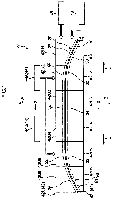
FIG. 1 is a perspective plan view showing a structure example of an ink-jet head;
FIG. 2 is a perspective view of a head module, and is a diagram including a partial cross-section view;
FIG. 3 is a perspective plan view of a liquid ejection surface of the head module;
FIG. 4 is a cross-section view showing an internal structure of the head module;
FIG. 5 is a perspective view showing a support structure for the head module;
FIG. 6 is a conceptual diagram of a joint part;
FIG. 7 is a partial enlarged view of FIG. 6 ;
FIG. 8 is an explanatory diagram schematically showing an arrangement of nozzle parts at a nozzle combining region;
FIG. 9 is an explanatory diagram showing an alternative example of the joint part;
FIG. 10 is a perspective plan view of a liquid ejection surface that shows a further alternative example of the joint part;
FIG. 11 is a perspective plan view of a liquid ejection surface that shows a further alternative example of the joint part;
FIG. 12 is an explanatory diagram schematically showing an arrangement of nozzle parts at the joint part shown in FIG. 11 ;
FIG. 13 is an explanatory diagram of amplification factor adjustment of drive voltage;
FIG. 14 is an explanatory diagram of the amplification factor of the drive voltage;
FIG. 15 is an explanatory diagram of an ejection volume distribution of the head module;
FIG. 16 is an explanatory diagram of an ejection volume distribution of the head module;
FIG. 17 is an explanatory diagram of an ejection volume distribution of the head module;
FIG. 18 is an explanatory diagram of an ejection volume distribution of the head module;
FIG. 19 is an explanatory diagram of an ejection volume distribution of the head module;
FIG. 20 is an explanatory diagram of an ejection volume distribution of the head module;
FIG. 21 is an explanatory diagram of an ejection volume distribution of the head module;
FIG. 22 is an explanatory diagram of an ejection volume distribution of the head module;
FIG. 23 is an explanatory diagram schematically showing a structure example of the ink-jet head;
FIG. 24 is an explanatory diagram schematically showing an alternative structure example of the ink-jet head;
FIG. 25 is an explanatory diagram schematically showing a structure example of an ink-jet head according to a comparative example;
FIG. 26 is a flowchart showing a flow of the procedure of an ink-jet head production method;
FIG. 27 is a flowchart showing a flow of the procedure of an ink-jet head production method;
FIG. 28 is a flowchart showing a flow of an ink-jet head production method;
FIG. 29 is an explanatory diagram schematically showing an example of a dot diameter evaluation chart;
FIG. 30 is a partial enlarged view of FIG. 29 ;
FIG. 31 is an explanatory diagram schematically showing an example of a line width evaluation chart;
FIG. 32 is a partial enlarged view of FIG. 31 ;
FIG. 33 is an explanatory diagram of an example in which nozzle parts arranged at the joint part are applied as a plurality of nozzle parts;
FIG. 34 is an explanatory diagram schematically showing the measurement of the ejection volume of liquid with use of a micro-syringe;
FIG. 35 is a conceptual diagram of the measurement of slope of ejection volume distribution according to Method 5;
FIG. 36 is an explanatory diagram of the slope of the ejection volume distribution of the head module that is derived by Method 5;
FIG. 37 is an explanatory diagram schematically showing a measurement method for the ejection volume at the joint part with use of a density evaluation pattern; and
FIG. 38 is a block diagram showing a schematic configuration of an ink-jet head production system.
Detailed description of the embodiments
Hereinafter, preferable embodiments of the present invention are described in detail with reference to the accompanying drawings.
[Structure of Ink-Jet Head]
<Overall Configuration>
FIG. 1 is a perspective plan view showing a structure example of an ink-jet head. An ink-jet head 21 shown in FIG. 1 has a structure in which a plurality of head modules 200 are jointed in the width direction of a medium 100 that is the direction orthogonal to the feed direction of the medium 100 . The ink-jet head in the specification is a mode of the liquid ejection head.
The structure in which the plurality of head modules 200 are jointed in the width direction of the medium 100 in the embodiment is a mode of the structure in which a plurality of head modules are arranged along a single direction.
The term “orthogonal” in the specification includes the case of being substantially orthogonal that is of the case of a cross at an angle exceeding 90 degrees or the case of a cross at an angle less than 90 degrees and that exhibits a function effect identical to the case of a cross at an angle of 90 degrees.
Further, the term “parallel” in the specification includes the case of being substantially parallel that exhibits a function effect identical to the case of being parallel, although two directions cross. Furthermore, the term “identical” in the specification includes the case of being substantially identical that makes it possible to obtain a similar function effect to the case of being identical, although there a difference in the configuration of the object.
In the specification, the width direction of the medium 100 is sometime described as the X-direction. Further, the feed direction of the medium 100 is sometimes described as the Y-direction or the medium feed direction. These terms can be replaced with each other when appropriate.
The ink-jet head 21 shown in FIG. 1 is a line-type ink-jet head in which a plurality of nozzle parts are arranged over a length equal to or greater than the total length L.sub.max of the medium 100 in the width direction of the medium 100 . The nozzle part, which is not illustrated in FIG. 1 , is illustrated in FIG. 4 while reference numeral 281 is assigned.
An identical structure can be applied to the plurality of head modules 200 constituting the ink-jet head 21 . Further, the head module 200 can function alone, as the ink-jet head.
<Structure of Head Module>
FIG. 2 is a perspective view of a head module, and is a diagram including a partial cross-section view. Hereinafter, identical reference numerals are assigned to constituents identical to constituents that are previously described, and the descriptions are omitted when appropriate.
Ink in the specification is a mode of the liquid, and the term “ink” and the term “liquid” can be replaced when appropriate. Further, in the specification, the term “discharge” and the term “ejection” can be treated as synonymous terms, and the term “discharge” and the term “ejection” can be replaced when appropriate.
The head module 200 has an ink supply unit including an ink supply chamber 232 , an ink circulation chamber 236 and the like, on the upper side in FIG. 2 , which is the opposite side to a liquid ejection surface 277 of a nozzle plate 275 .
The ink supply chamber 232 is connected with an ink tank not illustrated, through a supply-side individual passage 252 , and the ink circulation chamber 236 is connected with a collection tank not illustrated, through a collection-side individual passage 256 .
FIG. 3 is a perspective plan view of the liquid ejection surface of the head module. In FIG. 3 , nozzle openings 280 to be arranged on the liquid ejection surface 277 are illustrated so as to be reduced in number, but on the liquid ejection surface 277 of one head module 200 , a plurality of nozzle openings 280 are arranged by a two-dimensional arrangement.
The head module 200 has a planar shape of a parallelogram that includes a long-side edge surface along a V-direction having a slope of an angle β with respect to the direction orthogonal to the medium feed direction and a short-side edge surface along a W-direction having a slope of an angle a with respect to the medium feed direction, and the plurality of nozzle openings 280 are arranged in a matrix, in a row direction along the V-direction and in a column direction along the W-direction.
The arrangement of the nozzle openings 280 is not limited to the mode illustrated in FIG. 3 , and the plurality of nozzle openings 280 may be arranged in a row direction along the direction orthogonal to the medium feed direction and in a column direction crossing obliquely with respect to the direction orthogonal to the medium feed direction.
The matrix arrangement of the nozzle openings 280 is an arrangement of the nozzle openings 280 in which the arrangement intervals of the nozzle openings 280 are uniform on a projected nozzle array in the direction orthogonal to the medium feed direction, which is an array resulting from projecting the plurality of nozzle openings 280 in the direction orthogonal to the medium feed direction and arranging the plurality of nozzle openings 280 along the direction orthogonal to the medium feed direction.
FIG. 4 is a cross-section view showing an internal structure of the ink-jet head. Reference numeral 214 designates an ink supply path, reference numeral 218 designates a pressure chamber, reference numeral 216 designates an individual supply path that connects each pressure chamber 218 and the ink supply path 214 , reference numeral 220 designates a nozzle communication path that is connected from the pressure chamber 218 to the nozzle opening 280 , and reference numeral 226 designates a circulation individual passage that connects the nozzle communication path 220 and a circulation common passage 228 . The pressure chamber 218 is sometimes referred to as a liquid chamber.
A vibration plate 266 is provided on a passage structure body 210 that configures the ink supply path 214 , the individual supply path 216 , the pressure chamber 218 , the nozzle communication path 220 , the circulation individual passage 226 and the circulation common passage 228 . A piezoelectric element 230 having a laminate structure of a lower electrode 265 , a piezoelectric substance layer 231 and an upper electrode 264 is provided on the vibration plate 266 , through an adhesion layer 267 . The lower electrode 265 is sometimes referred to as a common electrode, and the upper electrode 264 is sometimes referred to as an individual electrode.
The upper electrode 264 is an individual electrode that is patterned so as to correspond to the shape of each pressure chamber 218 , and the piezoelectric element 230 is provided for each pressure chamber 218 .
The ink supply path 214 is connected with the ink supply chamber 232 shown in FIG. 2 , and the link is supplied from the ink supply path 214 through the individual supply path 216 to the pressure chamber 218 . Depending on input image data, a drive voltage is applied to the upper electrode 264 of the piezoelectric element 230 provided on the corresponding pressure chamber 218 . Thereby, the piezoelectric element 230 and the vibration plate 266 are transformed, and the volume of the pressure chamber 218 is changed. By a pressure change associated with this, the ink is discharged from the nozzle opening 280 through the nozzle communication path 220 .
It is possible to discharge the ink from the nozzle opening 280 , by controlling the drive of the piezoelectric element 230 corresponding to each nozzle opening 280 , depending on dot arrangement data that is generated from the input image data.
While the medium 100 is fed at a constant speed in the medium feed direction, the timing of the ink discharge from each nozzle opening 280 is controlled in concert with the feed speed, and thereby, it is possible to record a desired image on the medium 100 .
In the pressure chamber 218 provided so as to correspond to each nozzle opening 280 , the planar shape is a roughly square shape. At one of both corner parts on a diagonal line, an outlet to the nozzle opening 280 is provided, and at the other, the individual supply path 216 , which is an inlet of the supply ink, is provided. The illustration of the planar shape of the pressure chamber 218 is omitted.
Here, the planar shape of the pressure chamber is not limited to a square shape. As the planar shape of the pressure chamber, various shapes, as exemplified by a polygon such as a tetragon including a rhombus and a rectangle, a pentagon and a hexagon, a circle and an ellipse, are possible.
In the nozzle part 281 including the nozzle opening 280 and the nozzle communication path 220 , a circulation outlet is formed, and the nozzle part 281 is communicated with the circulation individual passage 226 through the circulation outlet. The ink that is of the ink in the nozzle communication path 220 and the nozzle opening 280 and that is not used for discharge is collected to the circulation common passage 228 through the circulation individual passage 226 .
The circulation common passage 228 is connected with the ink circulation chamber 236 shown in FIG. 2 , and at all times, the ink is collected to the circulation common passage 228 through the circulation individual passage 226 , resulting in the prevention of the thickening of the ink near the nozzle opening 280 when the discharge is not performed.
As a mode of the ejection element included in the head module, there is a mode of including one nozzle part 281 , a passage such as the pressure chamber 218 communicated with the one nozzle part 281 , and the piezoelectric element 230 corresponding to the nozzle part 281 .
Hereinafter, the term “nozzle opening” and the term “nozzle part” in the specification can be replaced with “ejection element”, when appropriate. Further, the term “nozzle opening” can be replaced with the term “nozzle part”, when appropriate.
Examples of the piezoelectric element 230 include a piezoelectric element 230 having a structure of being individually separated so as to correspond to the nozzle opening 280 shown in FIG. 3 . Needless to say, it is allowable to apply a structure in which the piezoelectric substance layer 231 is integrally formed for the plurality of nozzle parts 281 , the individual electrode is formed so as to correspond to each nozzle part 281 and an active region is formed for each nozzle part 281 .
It is allowable to apply a thermal system in which a heater is included within the pressure chamber 218 as a pressure generation element instead of the piezoelectric element, a drive voltage is supplied to the heater for heat generation and the ink in the pressure chamber 218 is discharged from the nozzle opening 280 by utilizing the film boiling phenomenon.
<Support Structure for Head Module>
FIG. 5 is a perspective view showing a support structure for the head module. FIG. 5 is a partial enlarged view of the ink-jet head 21 , and is a diagram when the head module 200 is viewed from the side of the liquid ejection surface 277 .
In FIG. 5 , the direction shown while reference character X is assigned is the longitudinal direction of the ink-jet head 21 . The longitudinal direction of the ink-jet head 21 is the width direction of the medium in a state in which the ink-jet head 21 is used while the ink-jet head 21 shown in FIG. 1 is mounted on the ink-jet recording apparatus.
Further, in FIG. 5 , the direction shown while reference character Y is assigned is the short direction of the ink-jet head 21 . The short direction of the ink-jet head 21 is the feed direction of the medium in a state in which the ink-jet head 21 is used while the ink-jet head 21 shown in FIG. 1 is mounted on the ink-jet recording apparatus.
In the specification, the “longitudinal direction of the ink-jet head 21 ” and the “width direction of the medium” can be replaced with each other. Similarly, the “short direction of the ink-jet head 21 ” and the “feed direction of the medium” can be replaced with each other.
Hereinafter, the longitudinal direction of the ink-jet head 21 is sometimes described as the X-direction. The short direction of the ink-jet head is sometimes described as the Y-direction.
The description continues in the full USPTO document.
 Lapsed, fee not paid14 drawings