Cross reference to related application
This application claims priority from Japanese Patent Application No. 2015-073380 filed Mar. 31, 2015. The entire content of the priority application is incorporated herein by reference.
Technical field
The present disclosure relates to a developing device used in an electrophotographic type image forming apparatus, and to an image forming apparatus provided with the developing device.
Background
There is conventionally known an electrophotographic type image forming apparatus including a toner box accommodating toner therein, and a developing device positioned upward of the toner box and provided with a photosensitive drum.
In this image forming apparatus, the toner box is formed with a supply opening at an intermediate portion thereof in an axial direction of the photosensitive drum, and return openings each being formed at each end portion of the toner box in the axial direction. Toner accommodated in the toner box is supplied to the developing device through the supply opening. Toner that has been supplied into the developing device is conveyed in the axial direction by an auger provided in the developing device, and is returned into the toner box through the return openings. Toner supplied to the developing device is supplied by a supply roller to a developing roller positioned upward of the supply roller while the toner is conveyed in the axial direction, and then, the toner supplied to the developing roller is supplied to the photosensitive drum positioned upward of the developing roller.
Summary
However, in this image forming apparatus, toner is conveyed from an axially intermediate position to axially outward positions in the developing device. Therefore, an amount of toner at an axially intermediate portion of the developing device may be different from an amount of toner at each axial end portion of the developing device.
In this case, a toner supply amount to the photosensitive drum may be different between the axially intermediate portion and the axial end portion. Accordingly, imaging quality may not be uniform in the axial direction in view of density.
In particular, in the toner conveying structure in which toner in the toner box is conveyed upward as performed in the above-described image forming apparatus, toner supply from the toner box to the developing roller using gravity of the toner cannot be performed. Consequently, non-uniform toner supply to the photosensitive drum may occur if the toner amount in the developing device is not uniform in the axial direction.
In view of the foregoing, it is an object of the disclosure to provide a developing device capable of uniformly supplying toner to a photosensitive drum in an axial direction thereof, and to provide an image forming apparatus provided with the developing device.
In order to attain the above and other objects, according to one aspect, the disclosure provides a developing device including: a casing; a photosensitive drum; a developing roller; a supply roller; a first conveying member; and a second conveying member. The casing defines an internal space therein and has a partitioning wall partitioning the internal space into a toner chamber and a developing chamber. The toner chamber accommodates toner therein. The developing chamber is positioned upward of the toner chamber. The partitioning wall has a supply opening and a discharge opening for providing communication between the toner chamber and the developing chamber. The photosensitive drum is configured to rotate about a first axis extending in an axial direction. The developing roller is accommodated in the developing chamber and configured to supply toner to the photosensitive drum. The developing roller is configured to rotate about a second axis. The supply roller is accommodated in the developing chamber and configured to supply toner to the developing roller. The supply roller is configured to rotate about a third axis positioned downward of the second axis. The supply opening and the discharge opening are positioned outward of the supply roller in the axial direction. The first conveying member is accommodated in the toner chamber and configured to convey the toner accommodated in the toner chamber into the developing chamber through the supply opening. The first conveying member is configured to rotate about a fourth axis positioned downward of the third axis. The second conveying member is accommodated in the developing chamber and configured to convey the toner supplied by the first conveying member from the supply opening to the discharge opening in the axial direction.
According to another aspect, the disclosure provides an image forming apparatus including: a developing device; and an exposure unit. The developing device includes: a casing; a photosensitive drum; a developing roller; a supply roller; a first conveying member; and a second conveying member. The casing defines an internal space therein and has a partitioning wall partitioning the internal space into a toner chamber and a developing chamber. The toner chamber accommodates toner therein. The developing chamber is positioned upward of the toner chamber. The partitioning wall has a supply opening and a discharge opening for providing communication between the toner chamber and the developing chamber. The photosensitive drum is configured to rotate about a first axis extending in an axial direction. The developing roller is accommodated in the developing chamber and configured to supply toner to the photosensitive drum. The developing roller is configured to rotate about a second axis. The supply roller is accommodated in the developing chamber and configured to supply toner to the developing roller. The supply roller is configured to rotate about a third axis positioned downward of the second axis. The supply opening and the discharge opening are positioned outward of the supply roller in the axial direction. The first conveying member is accommodated in the toner chamber and configured to convey the toner accommodated in the toner chamber into the developing chamber through the supply opening. The first conveying member is configured to rotate about a fourth axis positioned downward of the third axis. The first conveying member includes: a shaft extending in the axial direction; a first blade disposed at a position coincident with the supply opening in the axial direction, the first blade extending from the shaft toward an inner surface of the casing; and a second blade positioned closer to the discharge opening than the first blade to the discharge opening in the axial direction, the second blade extending from the shaft toward the inner surface of the casing, the second blade having a flexibility higher than that of the first blade. The second conveying member is accommodated in the developing chamber and configured to convey the toner supplied by the first conveying member from the supply opening to the discharge opening in the axial direction. The casing includes: a first accommodating wall accommodating the first blade and having an inner surface formed in an arcuate shape; and a second accommodating wall accommodating the second blade and having an inner surface extending linearly. The second accommodating wall is positioned closer to the discharge opening than the first accommodating wall to the discharge opening in the axial direction. The exposure unit is positioned downward of the casing. The exposure unit is configured to emit a laser beam to expose the photosensitive drum to the laser beam. The second accommodating wall extends along a path through which the laser beam passes.
Brief description of the drawings
The particular features and advantages of the embodiment(s) as well as other objects will become apparent from the following description taken in connection with the accompanying drawings, in which:
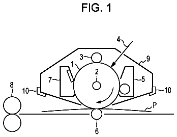
FIG. 1 is a central cross-sectional view of an image forming apparatus provided with a developing device according to one embodiment;
FIG. 2 is a central cross-sectional view of the developing device shown in FIG. 1 ;
FIG. 3 is a cross-sectional view of the developing device taken along a line A-A in FIG. 2 ;
FIG. 4A is a left side view of the developing device shown in FIG. 2 ;
FIG. 4B is a right side view of the developing device shown in FIG. 2 ;
FIG. 5 is a cross-sectional view of the developing device taken along a line B-B in FIG. 3 ;
FIG. 6 is a cross-sectional view of the developing device taken along a line C-C in FIG. 3 ;
FIG. 7A is a cross-sectional view of the developing device taken along a line D-D in FIG. 3 ;
FIG. 7B is a cross-sectional view of the developing device taken along the line D-D in FIG. 3 and showing a second position of a developing unit;
FIG. 8 is a cross-sectional view of the developing device taken along a line E-E in FIG. 3 ;
FIG. 9 is a cross-sectional view of the developing device taken along a line F-F in FIG. 3 ;
FIG. 10 is a cross-sectional view of the developing device taken along a line G-G in FIG. 3 ;
FIG. 11 is a cross-sectional view of the developing device taken along a line H-H in FIG. 3 ; and
FIG. 12 is a view illustrating how the developing device is mounted in and removed from a main casing of the image forming apparatus.
Detailed description
An image forming apparatus 1 provided with a plurality of developing devices 3 according to one embodiment will be described with reference to the accompanying drawings, wherein like parts and components are designated by the same reference numerals to avoid duplicating description. Directions referred to in the following description are based on directions indicated in the drawings.
1. Overall Structure of Image Forming Apparatus
As shown in FIG. 1 , the image forming apparatus 1 is a laser printer. The image forming apparatus 1 includes a main casing 2 formed with an opening 2 A ( FIG. 12 ); a plurality of (four) developing devices 3 ; an exposure unit 4 ; a belt unit 5 ; a secondary transfer roller 6 ; a fixing unit 7 ; and a reading unit 26 .
The main casing 2 is box-shaped, and is provided with a cover 8 and a supply tray 9 .
As shown in FIG. 12 , the opening 2 A is positioned at an upper end portion of the main casing 2 to provide communication between an interior and exterior of the main casing 2 in a vertical direction. The opening 2 A allows the plurality of developing devices 3 to pass therethrough.
As shown in FIG. 1 , the cover 8 is disposed at the upper end portion of the main casing 2 . The cover 8 has a plate shape that extends in a front-rear direction. The cover 8 is pivotally movable together with the belt unit 5 about an axis of pivot shafts 101 of a pivot member 82 (described later) between an open position opening the opening 2 A ( FIG. 12 ) and a closed position closing the opening 2 A ( FIG. 1 ).
The supply tray 9 is disposed at a lower end portion of the main casing 2 . The supply tray 9 is configured to accommodate sheets P.
The plurality of developing devices 3 is each a process cartridge. The plurality of developing devices 3 is detachable from and attachable to the main casing 2 . When attached to the main casing 2 , the four developing devices 3 are arrayed in the front-rear direction with a space between neighboring developing devices 3 . Each developing device 3 can be detached from the main casing 2 to an outside through the opening 2 A as shown in FIG. 12 . As shown in FIG. 2 , each of the four developing devices 3 includes a drum unit 10 and a developing unit 11 .
The drum unit 10 includes a photosensitive drum 12 and a charging roller 13 .
The photosensitive drum 12 is positioned at an upper end portion of the drum unit 10 . The photosensitive drum 12 has a cylindrical shape that extends in a left-right direction (an example of an axial direction). The photosensitive drum 12 is rotatable about a first axis A 1 extending in the left-right direction.
The charging roller 13 is positioned downward of the photosensitive drum 12 . The charging roller 13 is in contact with a lower end portion of the photosensitive drum 12 . The charging roller 13 is configured to charge a surface of the photosensitive drum 12 .
The developing unit 11 is positioned diagonally forward and downward of the photosensitive drum 12 . The developing unit 11 includes a developing roller 15 , a supply roller 16 , a blade 17 , and a toner chamber 18 .
The developing roller 15 is positioned at an upper end portion of the developing unit 11 . The developing roller 15 is in contact with a lower-front end portion of the photosensitive drum 12 . The developing roller 15 is configured to supply toner to the photosensitive drum 12 . The developing roller 15 is rotatable about a second axis A 2 positioned downward of the first axis A 1 .
The supply roller 16 is positioned diagonally forward and downward of the developing roller 15 . The supply roller 16 is in contact with a lower-front end portion of the developing roller 15 . The supply roller 16 is configured to supply toner to the developing roller 15 . The supply roller 16 is rotatable about a third axis A 3 positioned downward of the second axis A 2 .
The blade 17 is positioned diagonally rearward and downward of the developing roller 15 . The blade 17 is in contact with a lower-rear end portion of the developing roller 15 . The blade 17 is configured to regulate a thickness of a toner layer formed over a surface of the developing roller 15 .
The toner chamber 18 is positioned downward of the supply roller 16 . The toner chamber 18 has a cylindrical shape that extends in the left-right direction. The toner chamber 18 is configured to accommodate therein toner.
As shown in FIG. 1 , the exposure unit 4 is positioned downward of the four developing devices 3 . The exposure unit 4 is configured to irradiate a laser beam L based on image data. The laser beam L is incident on the surface of each photosensitive drum 12 , passing between the developing unit 11 and the corresponding charging roller 13 .
The belt unit 5 is positioned upward of the four developing devices 3 , and extends in the front-rear direction. The belt unit 5 includes a first roller 19 positioned at a rear end portion of the belt unit 5 ; a second roller 20 positioned at a front end portion of the belt unit 5 ; a third roller 21 positioned diagonally forward and downward of the first roller 19 ; a belt 22 ; and a plurality of (four) primary transfer rollers 23 .
The belt 22 is an endless belt looped over the first roller 19 , the second roller 20 , and the third roller 21 . The belt 22 has a lower portion that is in contact with the four photosensitive drums 12 . The belt 22 is circularly movable around the first roller 19 , the second roller 20 , and the third roller 21 such that the lower portion of the belt 22 is moved rearward.
The four primary transfer rollers 23 are arrayed in the front-rear direction between the second roller 20 and the third roller 21 , with a space between neighboring primary transfer rollers 23 . The primary transfer rollers 23 are positioned upward of the corresponding photosensitive drums 12 , with the belt 22 interposed therebetween.
The secondary transfer roller 6 is positioned rearward of the first roller 19 . The secondary transfer roller 6 nips the belt 22 in cooperation with the first roller 19 .
The fixing unit 7 is positioned upward of the secondary transfer roller 6 . The fixing unit 7 includes a heating roller 24 , and a pressure roller 25 in pressure contact with the heating roller 24 .
The reading unit 26 is positioned above the main casing 2 . More specifically, the reading unit 26 is positioned upward of the cover 8 with a gap therebetween. The reading unit 26 is a flat-bed type image scanner. The reading unit 26 is configured to read image data from an original document.
Upon start of an image-forming operation in the image forming apparatus 1 , the exposure unit 4 irradiates the laser beam L, so that the surfaces of the photosensitive drums 12 are exposed to the laser beam L. Thus, electrostatic latent images based on image data are formed on the surfaces of the photosensitive drums 12 , respectively.
Then, toner is supplied onto the electrostatic latent images on the surfaces of the photosensitive drums 12 by the corresponding developing rollers 15 . Thus, toner images are carried on the surfaces of the photosensitive drums 12 .
Then, the toner images on the surfaces of the photosensitive drums 12 are transferred onto the belt 22 .
In the meantime, the sheets P are supplied from the supply tray 9 one at a prescribed timing to a position between the belt 22 and the secondary transfer roller 6 . The toner image on the belt 22 is transferred onto the sheet P when the sheet P passes between the belt 22 and the secondary transfer roller 6 .
Subsequently, the sheet P is heated and pressed when the sheet P passes between the heating roller 24 and the pressure roller 25 . Thus, the toner image carried on the sheet P is thermally fixed to the sheet P.
Then, the sheet P is delivered onto the cover 8 .
2. Developing Device
Drum Unit
As shown in FIGS. 2, 4A, and 4B , the drum unit 10 includes a left side plate 31 L having a hole 36 formed therein, a right side plate 31 R having a hole 36 formed therein, a drum cleaner 32 , and a handle 33 .
As shown in FIGS. 3 and 4A , the left side plate 31 L is positioned at a left end portion of the drum unit 10 . The left side plate 31 L has a rectangular shape in a side view. The left side plate 31 L is elongated both in the vertical direction and in the front-rear direction. The left side plate 31 L includes a drum support part 35 .
The drum support part 35 is positioned at a top end portion of the left side plate 31 L. The drum support part 35 has a cylindrical shape that extends in the left-right direction. A left end portion of the photosensitive drum 12 is rotatably fitted in the drum support part 35 .
The hole 36 is formed in the left side plate 31 L at a position diagonally downward and forward of the drum support part 35 . The hole 36 penetrates the left side plate 31 L in the left-right direction. The hole 36 has a circular shape in a side view.
As shown in FIGS. 3 and 4B , the right side plate 31 R is positioned at a right end portion of the drum unit 10 . The right side plate 31 R has a rectangular shape in a side view. The right side plate 31 R is elongated both in the vertical direction and in the front-rear direction. Similar to the left side plate 31 L, the right side plate 31 R includes a drum support part 35 . A right end portion of the photosensitive drum 12 is rotatably fitted in the drum support part 35 of the right side plate 31 R.
As shown in FIG. 2 , the drum cleaner 32 is positioned rearward of the photosensitive drum 12 and the charging roller 13 . The drum cleaner 32 includes an accommodating portion 37 , and a scraping blade 38 .
The accommodating portion 37 has a flattened box shape and is elongated both in the vertical direction and in the left-right direction. The accommodating portion 37 is positioned between the left side plate 31 L and the right side plate 31 R. The accommodating portion 37 includes an opposing wall 37 B having an opening 37 A and a plurality of (two) recessed parts 37 C (see FIGS. 7A and 11 ).
The opposing wall 37 B constitutes a front wall of the accommodating portion 37 . The opposing wall 37 B extends linearly in a direction from upper front to lower rear.
The opening 37 A is positioned at a top end portion of the opposing wall 37 B. The opening 37 A penetrates the top end portion of the opposing wall 37 B in the front-rear direction. The opening 37 A confronts a rear portion of a circumferential surface of the photosensitive drum 12 .
As shown in FIGS. 7A and 11 , the two recessed parts 37 C include a left recessed part 37 C (see FIG. 11 ) positioned at a left end portion of the accommodating portion 37 , and a right recessed part 37 C (see FIG. 7A ) positioned at a right end portion of the accommodating portion 37 . The two recessed parts 37 C are positioned downward of the charging roller 13 . The two recessed parts 37 C are recessed rearward from a front surface of the accommodating portion 37 .
As shown in FIG. 2 , the scraping blade 38 is positioned at a top end portion of the drum cleaner 32 . The scraping blade 38 has a plate shape that is elongated both in the vertical direction and in the left-right direction. The scraping blade 38 is attached to a front surface of the opposing wall 37 B on a lower edge of the opening 37 A. A top end portion of the scraping blade 38 is positioned within the opening 37 A and contacts the rear portion of the circumferential surface of the photosensitive drum 12 .
As shown in FIGS. 2 and 3 , the handle 33 is positioned at a top end portion of the drum unit 10 . The handle 33 is pivotally movable between an upright position (indicated in dashed lines in FIG. 2 ) extending vertically upward, and an inclined position (indicated by solid lines in FIG. 2 ) inclined forward from the upright position. The handle 33 is constantly urged toward the upright position by two coil springs 39 (see also FIGS. 4A and 4B ).
Developing Unit
As shown in FIGS. 2 and 3 , the developing unit 11 is positioned between the left side plate 31 L and the right side plate 31 R. The developing unit 11 is pivotally movable between a first position (see FIG. 7A ) in which the developing roller 15 contacts the photosensitive drum 12 , and a second position (see FIG. 7B ) in which the developing roller 15 is separated from the photosensitive drum 12 . The following description of the developing unit 11 will be based on the developing unit 11 being in its first position. Tension springs 30 (see FIG. 7B ) constantly urge the developing unit 11 toward its second position. In addition to the toner chamber 18 described earlier, the developing unit 11 includes a developing chamber 42 , a left support shaft 64 L, and a right support shaft 64 R.
(2-1) Developing Chamber
As shown in FIGS. 2 and 3 , the developing chamber 42 is positioned at a top portion of the developing unit 11 . The developing chamber 42 includes a first frame 40 , the developing roller 15 , the supply roller 16 , and the blade 17 , a second conveying member 65 , a plurality of end seals 50 , a pair of side seals 52 (see FIG. 6 ; also referred to as a left side seal 52 L and a right side seal 52 R, note that the left side seal 52 L is not shown in the drawings), and a pair of shaft seals 51 (see FIG. 6 ).
(2-1-1) First Frame
The first frame 40 has a box shape with an upper-rear opening. The first frame 40 includes a first side wall 45 R, a second side wall 45 L, a bottom wall 46 , a front wall 47 , and a rear wall 48 .
The first side wall 45 R is positioned at a right end portion of the first frame 40 . The first side wall 45 R extends both in the vertical direction and in the front-rear direction. The first side wall 45 R includes a toner supply part 55 having a supply opening 55 A, and a right seal support part 49 R.
As shown in FIGS. 3 and 5 , the toner supply part 55 is positioned on a right end portion of the first frame 40 . The toner supply part 55 protrudes rightward from a lower-rear end portion of the first side wall 45 R. The toner supply part 55 is positioned further rightward than the supply roller 16 . The toner supply part 55 has a cylindrical shape whose right end is closed. A left end of the toner supply part 55 is in communication with a lower-rear portion of an internal space defined by the first frame 40 .
The supply opening 55 A is positioned at a front end portion of the toner supply part 55 . In other words, the supply opening 55 A is positioned forward of the second conveying member 65 and on a side the same as a side where the supply roller 16 is positioned relative to the second conveying member 65 . The supply opening 55 A is positioned further rightward than a right end face of a cover part 16 A described later. The supply opening 55 A is also positioned between the supply roller 16 and the second conveying member 65 when viewed in the left-right direction. The supply opening 55 A is positioned further rightward than the supply roller 16 . The supply opening 55 A penetrates a front portion of a circumferential wall of the toner supply part 55 in the front-rear direction.
As shown in FIGS. 3 and 6 , the right seal support part 49 R is positioned between a right end portion of the second conveying member 65 and a right end portion of the developing roller 15 . The right seal support part 49 R protrudes leftward (inward) from a left surface (inner surface) of the first side wall 45 R. The right seal support part 49 R has a plate shape that is elongated in the left-right direction.
The second side wall 45 L is positioned at a left end portion of the first frame 40 . The second side wall 45 L extends both in the vertical direction and in the front-rear direction. The second side wall 45 L includes a toner discharge part 54 having a discharge opening 54 A, and a left seal support part 49 L.
As shown in FIGS. 3 and 8 , the toner discharge part 54 is positioned at a left end portion of the first frame 40 . The toner discharge part 54 protrudes leftward from a lower-rear end portion of the second side wall 45 L. The toner discharge part 54 is positioned further leftward than the supply roller 16 . The toner discharge part 54 has a cylindrical shape whose left end is closed. A right end of the toner discharge part 54 is in communication with the lower-rear portion of the internal space defined by the first frame 40 .
The discharge opening 54 A is positioned at a bottom end portion of the toner discharge part 54 . The discharge opening 54 A is positioned further leftward than the supply roller 16 . The discharge opening 54 A is also positioned further leftward than the left end face of the cover part 16 A. The discharge opening 54 A penetrates a bottom portion of a circumferential wall of the toner discharge part 54 in the vertical direction.
As shown in FIG. 3 , the left seal support part 49 L is positioned between a left end portion of the second conveying member 65 and a left end portion of the developing roller 15 . The left seal support part 49 L protrudes rightward (inward) from a right surface (inner surface) of the second side wall 45 L. The left seal support part 49 L has a plate shape that is elongated in the left-right direction.
As shown in FIGS. 2 and 3 , the bottom wall 46 is positioned at a bottom end portion of the first frame 40 . The bottom wall 46 is positioned between the second side wall 45 L and the first side wall 45 R. The bottom wall 46 extends both in the left-right direction and in the front-rear direction. A left edge of the bottom wall 46 is connected to a bottom edge of the second side wall 45 L, while a right edge of the bottom wall 46 is connected to a bottom edge of the first side wall 45 R. The bottom wall 46 configures a partitioning wall together with the circumferential wall of the toner supply part 55 and the circumferential wall of the toner discharge part 54 . The bottom wall 46 partitions the toner chamber 18 and the developing chamber 42 .
The front wall 47 is positioned at a front end portion of the first frame 40 . The front wall 47 extends upward from a front edge of the bottom wall 46 . A left edge of the front wall 47 is connected to a front edge of the second side wall 45 L, while a right edge of the front wall 47 is connected to a front edge of the first side wall 45 R.
The rear wall 48 is positioned at a rear end portion of the first frame 40 . The rear wall 48 extends upward from a rear edge of the bottom wall 46 . A left edge of the rear wall 48 is connected to a rear edge of the second side wall 45 L, while a right edge of the rear wall 48 is connected to a rear edge of the first side wall 45 R.
(2-1-2) Developing Roller
As shown in FIGS. 2 and 3 , the developing roller 15 is accommodated in an upper portion of the internal space defined by the first frame 40 . The developing roller 15 includes a cover part 15 A as an example of a developing cover part, and a shaft 15 B as an example of a developing shaft.
The cover part 15 A constitutes an outer circumferential portion of the developing roller 15 in a radial direction of the developing roller 15 . The cover part 15 A covers the shaft 15 B. The cover part 15 A has a cylindrical shape and extends in the left-right direction.
The shaft 15 B constitutes a center portion of the developing roller 15 in the radial direction of the developing roller 15 . The shaft 15 B has a columnar shape and extends in the left-right direction. The shaft 15 B is inserted into an interior of the cover part 15 A such that an outer circumferential surface of the shaft 15 B is in contact with an inner circumferential surface of the cover part 15 A. A left end portion of the shaft 15 B protrudes further leftward than a left end face of the cover part 15 A and is rotatably supported at the second side wall 45 L. Similarly, a right end portion of the shaft 15 B protrudes further rightward than a right end face of the cover part 15 A and is rotatably supported at the first side wall 45 R.
(2-1-3) Supply Roller
The supply roller 16 is accommodated in a lower-front portion of the internal space defined by the first frame 40 . The supply roller 16 includes the cover part 16 A as an example of a supply cover part, and a shaft 16 B as an example of a supply shaft.
The cover part 16 A constitutes an outer circumferential portion of the supply roller 16 in a radial direction of the supply roller 16 . The cover part 16 A has a cylindrical shape and extends in the left-right direction. The cover part 16 A is in contact with a lower-front portion of a circumferential surface of the cover part 15 A.
The shaft 16 B constitutes a center portion of the supply roller 16 in the radial direction of the supply roller 16 . The shaft 16 B has a columnar shape and extends in the left-right direction. The shaft 16 B is inserted into an interior of the cover part 16 A such that an outer circumferential surface of the shaft 16 B is in contact with an inner circumferential surface of the cover part 16 A. A left end portion of the shaft 16 B protrudes further leftward than a left end face of the cover part 16 A and is rotatably supported at the second side wall 45 L. Similarly, a right end portion of the shaft 16 B protrudes further rightward than a right end face of the cover part 16 A and is rotatably supported at the first side wall 45 R.
(2-1-4) Blade
The blade 17 includes a support plate 17 A, and a contact part 17 B.
The support plate 17 A has a plate shape that is elongated both in the front-rear direction and in the left-right direction. The support plate 17 A is formed of metal, for example. A rear end portion of the support plate 17 A is supported at a top end portion of the rear wall 48 .
The contact part 17 B is supported on a top surface of the support plate 17 A at a front end portion thereof. The contact part 17 B has a plate shape that is elongated in the left-right direction. The contact part 17 B is formed of rubber, for example. The contact part 17 B is in contact with a bottom portion of an outer circumferential surface of the cover part 15 A.
(2-1-5) Second Conveying Member
The second conveying member 65 is accommodated in the lower-rear portion of the internal space defined by the first frame 40 . The second conveying member 65 is positioned rearward of the supply roller 16 . The second conveying member 65 is juxtaposed with the supply roller 16 in the front-rear direction (horizontally). The second conveying member 65 extends in the left-right direction. The second conveying member 65 is an auger screw. The second conveying member 65 includes a shaft 65 A, and a helical blade 65 B.
The shaft 65 A has a columnar shape that extends in the left-right direction. A left end portion of the shaft 65 A is rotatably supported at a left wall of the toner discharge part 54 and the left support shaft 64 L, while a right end portion of the shaft 65 A is rotatably supported at a right wall of the toner supply part 55 and the right support shaft 64 R.
The helical blade 65 B protrudes radially outward from a circumferential surface of the shaft 65 A. The helical blade 65 B has a helical shape, with its axis extending in the left-right direction. The helical blade 65 B is positioned between the right wall of the toner supply part 55 and the left wall of the toner discharge part 54 . A right end portion of the helical blade 65 B confronts the supply opening 55 A, while a left end portion of the helical blade 65 B confronts the discharge opening 54 A.
(2-1-6) Seals and Related Structures in Developing Chamber
As shown in FIGS. 3 and 6 , the plurality of end seals 50 includes an end seal 50 A that seals a gap between a left end of the support plate 17 A and the left seal support part 49 L, an end seal 50 B that seals a gap between the left end of the support plate 17 A and a left end portion of the cover part 15 A, an end seal 50 C that seals a gap between a right end of the support plate 17 A and the right seal support part 49 R, and an end seal 50 D that seals a gap between the right end of the support plate 17 A and a right end portion of the cover part 15 A. The end seals 50 each have a plate shape that extends in the left-right direction. The end seals 50 are formed of sponge, for example.
The pair of side seals 52 is positioned forward of the end seals 50 . The side seals 52 each have a plate shape that is elongated in the front-rear direction. The side seals 52 contact a bottom portion of the outer circumferential surface of the cover part 15 A at left and right end portions, respectively. The right side seal 52 R as an example of a first seal contacts the right end portion of the cover part 15 A and is positioned further leftward (inward) than the supply opening 55 A. The left side seal 52 L as an example of a second seal contacts the left end portion of the cover part 15 A and is positioned further rightward (inward) than the discharge opening 54 A.
The pair of shaft seals 51 is positioned below the pair of side seals 52 , respectively. The shaft seals 51 each have a cylindrical shape that extends in the left-right direction. A top surface of each shaft seal 51 contacts a bottom surface of the corresponding side seal 52 . Left and right end portions of the shaft 16 B are respectively inserted into the shaft seals 51 such that the outer circumferential surface of the shaft 16 B contacts inner circumferential surfaces of the shaft seals 51 .
(2-2) Toner Chamber
As shown in FIGS. 2 and 3 , the toner chamber 18 is positioned beneath the developing chamber 42 . The toner chamber 18 includes a second frame 41 , and a first conveying member 60 .
(2-2-1) Second Frame
The second frame 41 has a cylindrical shape that extends in the left-right direction. The second frame 41 has a left-right dimension greater than that of the first frame 40 . Together with the first frame 40 , the second frame 41 configures a casing. The second frame 41 includes a left side wall 43 L, a right side wall 43 R, and a circumferential wall 44 having a recessed part 53 .
As shown in FIGS. 3 and 11 , the left side wall 43 L is positioned at a left end portion of the toner chamber 18 . The left side wall 43 L is positioned further leftward than the second side wall 45 L of the first frame 40 . The left side wall 43 L extends both in the vertical direction and in the front-rear direction. The left side wall 43 L has a circular shape in a side view.
As shown in FIGS. 3, 7A and 7B , the right side wall 43 R is positioned at a right end portion of the toner chamber 18 . The right side wall 43 R is positioned further rightward than the first side wall 45 R of the first frame 40 . The right side wall 43 R extends both in the vertical direction and in the front-rear direction. The right side wall 43 R has a circular shape in a side view.
As shown in FIGS. 2 and 3 , the circumferential wall 44 is positioned between the left side wall 43 L and the right side wall 43 R. The circumferential wall 44 has a cylindrical shape. A left edge of the circumferential wall 44 is connected to an edge of the left side wall 43 L, while a right edge of the circumferential wall 44 is connected to an edge of the right side wall 43 R. The circumferential wall 44 includes a first circumferential wall 44 A as an example of a first accommodating wall, a second circumferential wall 44 B, and a third circumferential wall 44 C.
The recessed part 53 is positioned at an intermediate portion of the circumferential wall 44 in the left-right direction. The recessed part 53 is recessed forward from a rear end portion of the circumferential wall 44 . The recessed part 53 has a left-right dimension approximately equal to a left-right dimension of the developing chamber 42 . Further, the left-right dimension of the recessed part 53 is greater than a left-right dimension of the cover part 15 A and smaller than a left-right dimension of the photosensitive drum 12 .
As shown in FIGS. 3 and 5 , the first circumferential wall 44 A constitutes a right end portion of the circumferential wall 44 . The first circumferential wall 44 A is positioned further rightward than the developing chamber 42 . The first circumferential wall 44 A is also positioned further rightward than the recessed part 53 . The first circumferential wall 44 A has an arcuate shape that extends in a circumferential direction of the toner chamber 18 . Hence, an inner surface of the first circumferential wall 44 A has an arcuate shape. An upper edge of the first circumferential wall 44 A is connected to the toner supply part 55 . Consequently, the supply opening 55 A provides communication between the toner chamber 18 and the toner supply part 55 of the developing chamber 42 .
As shown in FIGS. 3 and 8 , the second circumferential wall 44 B constitutes a left end portion of the circumferential wall 44 . The second circumferential wall 44 B is positioned further leftward than the developing chamber 42 . The second circumferential wall 44 B is also positioned further leftward than the recessed part 53 . The second circumferential wall 44 B has an arcuate shape that extends in the circumferential direction of the toner chamber 18 . An upper edge of the second circumferential wall 44 B is connected to the toner discharge part 54 . Consequently, the discharge opening 54 A provides communication between the toner chamber 18 and the toner discharge part 54 of the developing chamber 42 .
As shown in FIGS. 2 and 3 , the third circumferential wall 44 C is positioned between the first circumferential wall 44 A and the second circumferential wall 44 B. Hence, the third circumferential wall 44 C is positioned closer to the discharge opening 54 A in the left-right direction than the first circumferential wall 44 A to the discharge opening 54 A. The third circumferential wall 44 C is positioned below the developing chamber 42 . The third circumferential wall 44 C includes a flat wall 44 D as an example of a second accommodating wall, an arc wall 44 E, and a plurality of (two) connecting walls 44 F.
The flat wall 44 D constitutes a rear wall of the third circumferential wall 44 C. The flat wall 44 D forms a bottom wall in the recessed part 53 . The flat wall 44 D extends linearly in a direction from lower rear to upper front. Hence, an inner surface of the flat wall 44 D extends linearly. A top edge of the flat wall 44 D is connected to a rear edge on a bottom end portion of the developing chamber 42 .
The description continues in the full USPTO document.
 Lapsed, fee not paid6 drawings

