Field of invention
The invention relates to a method of analysing video images of a sports motion. More particularly, the invention relates to identification of key motion positions within a video and automatic extraction of segments of a video containing a sports motion.
Background to the invention
Participation in many sports involves repeating certain motions over and over again. The consistent ability to perform these motions in a particular way is usually critical to good performance in the sport. Different methods have been found to help participants develop the ability to repeatedly move in a certain way. Increasingly, technology is being used in such methods to improve performance in sports.
Video analysis is an important part of modern sports training. The ability to see oneself perform a motion helps an individual identify flaws in technique and correct them. Furthermore, video analysis techniques can be applied to video of a sports motion to help identify aspects of a motion that need changing or identify aspects of a motion performed correctly for positive feedback.
Taking golf as an example, a golfer's swing technique is critical to their ability to strike a golf ball consistently and therefore perform well. Over the years, a preferred golf swing technique has been identified and most golfers strive to model their swings as closely as possible to this preferred technique. Video analysis has been used in golf to improve golfers' swings.
A straightforward form of video analysis is simply to record a golf swing and watch it back to identify flaws that cannot be discerned by the golfer themselves or by a tutor. Video footage can be paused so that individual frames showing a particular swing position can be analysed.
Another analysis method is to display a person's golf swing next to that of another, to more easily identify differences compared to a model swing. Some existing methods involve synchronising the two swings so that corresponding swing positions are shown together, which makes comparison easier.
To analyse a golf swing, it is useful to examine certain swing positions, such as the address position, top swing position, impact position and finish position. It is therefore desirable to identify the video frames showing the golfer in those positions.
When capturing video footage of a golf swing, there may be a large amount of footage recorded either side of the swing itself, for example when a player is preparing to swing. Such footage is largely redundant and can make it difficult to quickly identify the actual swing motion and may take up precious memory space in the case of stored digital video data. It is therefore desirable to extract segments of video footage that contain just the golf swing motion.
Some existing methods of golf swing video analysis achieve these aims, i.e. extraction of a segment of video containing a golf swing or identification key swing positions, or both. It will be readily understood that identification of the address and finish positions allows the segment of video showing the golf swing to be extracted: the golf swing is shown in the portion of video in between the address and finish positions.
Examples of such existing methods are: Manually examining the video swing footage and identifying the segment showing the golf swing and frames showing key motion positions. This is time intensive as it requires a user to look through all the video footage. Detecting the noise of impact to identify the moment of impact, as in U.S. Pat. No. 6,537,076 and U.S. Pat. No. 6,567,536. The rest of the swing is assumed to be within a certain time either side of this moment. This method requires an audio detection device working with the video capture device and is only able to accurately detect the impact position. This method will not reliably work for swings of different tempos. Using other types of sensor to detect parts of the swing, for example pressure mats, as in US 2006/0281060. However, this method requires the use of another type of sensor, which may be expensive and not always be convenient. Placing colour markers or other identifiable labels on the golfer and golf club and automatically detecting their positions in the video footage, as in U.S. Pat. No. 7,097,459, U.S. Pat. No. 7,704,157 and U.S. Pat. No. 7,857,708. However, this requires the use of markers or labels which may not always be available and errors may occur if the markers are not placed in the correct locations, Using object recognition-based methods, such as identification of a player's silhouette or body segments, as in US 2010/0303303. However, these methods involve solving a difficult and time-consuming problem of human shape recognition before applying golf swing analysis methods. These methods are therefore very complex, require high levels of processing power/memory and take some time to product results. Detecting the position of the ball in the video footage and how it changes during the motion, as in KR 101002846. While this method avoids the need for equipment beyond a video capture device and processor, it relies on the presence of a ball, which may not always be available. It also assumes the ball is covered by the club head during the address position and therefore is not useful for analysing video recorded from, an angle in which the ball is not covered by the club head at address. Finally, it estimates which frame shows the finish position by making certain assumptions which may not always be true.
In another method of analysing a golf swing, the position of the golf club is detected using straight line detection methods such as Hough or Radon transforms, as in U.S. Pat. No. 7,200,282. Such methods may be useful for segments of video in which the golf club is relatively stationary but they may not work as effectively if the club is moving quickly and the image is blurred. These methods are also computationally intensive.
Many of the above techniques can also be applied to motion analysis in other sports.
It is therefore an object of the invention to provide an improved method of analysing video images of sports motion that overcomes at least some of the disadvantages discussed above.
Video capture devices have become increasingly widespread in recent years. Video images can be captured on many personal electronic devices such as digital cameras and mobile phones. It has therefore become very easy for anyone to capture video footage of an individual executing a particular sports motion. It would be convenient if the same device used to capture video footage could be used to analyse the footage. It is therefore an alternative object of the invention to provide a method of analysing video images of sports motion that can be performed by a personal electronic device.
It is an alternative object of the invention to provide an improved apparatus and/or system for analysing video images of sports motion
Alternatively, it is an object of the invention to at least provide the public with a useful choice.
Summary of the invention
According to a first aspect of the invention, there is provided a method of analysing a video, at least a portion of the video displaying a sports motion, the method comprising the steps of: receiving data representative of a number T of image frames; calculating, for each of a number T.sub.C of the image frames, one or more frame difference measures between the image frame and another image frame; analysing the frame difference measures to identify a plurality of image frames that each show a key position of the sports motion.
Preferably, the method further comprises the step of identifying the portion of the video displaying the sports motion. More preferably, the step of identifying the portion of the video displaying the sports motion comprises selecting image frames between two of the key positions of the sports motion.
Preferably, the method further comprises identifying one or more motion phases of the sports motion from the frame difference measures. More preferably, the method comprises using identification of the motion phases to identify the key positions of the sports motion.
It will be understood that “frame difference measures” are quantities that are indicative of differences in the video data between image frames. In preferred embodiments of the invention, the one or more frame difference measures comprise one or more of the following: 1. a measure of the amount of movement between image frames; 2. a measure of the position of movement between image frames; and 3. a measure of the velocity or a derivative thereof (such as acceleration) of movement between image frames.
Each frame difference measure may be a global measure or local measure of the difference between frames. A global measure may be understood to be a measure at the level of substantially the whole image. A local measure may be understood to be a measure at the pixel or sub-image level.
Preferably, each image frame comprises a number P of pixels or groups of pixels and the method further comprises: for each of the number T.sub.C of the image frames, comparing each of a number P.sub.C of pixels or groups of pixels with corresponding pixels or groups of pixels in the other image frame and calculating one or more pixel difference measures.
More preferably, the pixel difference measures comprise intensity differences between pixels or groups of pixels.
Preferably, the method comprises calculating the one or more frame difference measures based on the one or more pixel difference measures.
More preferably, the method comprises calculating statistical values of pixel difference measures between image frames. Preferably, the method comprises calculating statistical values of pixel difference measures exceeding a predetermined threshold. The pixel difference measures may comprise one or more of the following: 1. a measure of the amount of pixel movement between image frames; 2. a measure of the position of pixel movement between image frames; and 3. a measure of the velocity or a derivative thereof (such as acceleration) of pixel movement between image frames.
More preferably, the statistical values of pixel difference measures calculated may comprise one or more of: median, mean, nth-percentile, standard deviation.
In a second preferred embodiment of the invention, the method comprises: for each of the number T.sub.C of the image frames, determining optical flow between the pixels or groups of pixels and the corresponding pixels or groups of pixels in the other image frame.
More preferably, the step of determining optical flow comprises determining local correlations between pixels or groups of pixels between each image frame and the other image frame.
In a preferred embodiment of the invention, the step of analysing the frame difference measures to identify a plurality of image frames that each show a key position of the sports motion comprises: identifying a plurality of patterns in temporal variations in frame difference measures; and associating each pattern with one of the motion phases of the sports motion.
Preferably, the step of identifying a plurality of patterns comprises identifying peaks and/or troughs in the temporal variations in frame difference measures.
More preferably, the step of identifying a plurality of patterns comprises identifying peaks and/or troughs in vertical pixel movements between image frames.
In certain embodiments of the invention, a decision model is used to analyse the frame difference measures to identify a plurality of image frames that each show a key position of the sports motion.
In a preferred embodiment of the invention, the method comprises the step of applying an image improvement algorithm to the video. For example, in one embodiment, an image stabilisation algorithm is applied to the video.
In one embodiment of the invention, the method comprises applying an image stabilisation algorithm comprising computing optical flow vectors and subsequently using the optical flow vectors to calculate the frame difference measures.
In one embodiment of the invention, the image improvement algorithm may comprise a contrast enhancement algorithm.
Preferably, the step of analysing the frame difference measures comprises applying a noise reduction filter to the temporal variations in frame difference measures.
Preferably, for each step of calculating the frame difference measures, the other image frame is separated from the image frame by a pre-determined number of image frames. More preferably, the other image frame is the previous or succeeding frame.
Preferably, the number T.sub.C of image frames for which frame difference measures are calculated is equal to the number T of image frames in the video data.
Preferably, the number P.sub.C of pixels or groups of pixels is equal to the number P of pixels or groups of pixels in the image frame.
Preferably, the method further comprises writing data representative of the image frames showing the key positions of the sports motion and/or the portion of the video displaying the sports motion to a computer-readable medium. The method may further comprise erasing all other data.
More preferably, the method comprises the step of outputting the image frames showing the key positions of the sports motion and/or the portion of the video displaying the sports motion on a display device.
Preferably, the method comprises recording the video on a video capture device. More preferably, the method of analysing the video is performed on the video capture device. In one embodiment, the video capture device is a mobile telephone.
Preferably, the method further comprises synchronising two sports motions and displaying the two sports motions together on the display device. The two sports motions may be alternative views of one person performing the sports motion or the same view of two people performing the sports motion. More preferably, the method of synchronising comprises displaying image frames of the key positions of each sports motion at the same time.
Preferably, the method further comprises calculating a value indicative of the duration of the sports motion. More preferably, the value indicative of the duration of the sports motion comprises the time elapsed between image frames showing two of the key positions.
In a preferred embodiment of the invention, the sports motion is a golf swing.
In a preferred embodiment of the invention, the method further comprises identifying an object in one or more of the image frames. More preferably, the method comprises identifying the object in at least one of the image frames showing one of the key positions of the sports motion.
For example, the method comprises identifying a golf club in one or more image frames, and particularly the images frames showing address and finish positions. Hough or Radon transform methods may be used to identify the golf club.
Preferably, the method comprises constructing one or more lines and displaying the line(s) on one or more of the image frames.
For example, in one embodiment the method comprises constructing a first line through the golf club in the address position and a second line at approximately 17° to the first line (above the first line) and displaying the lines in one or more image frames of the side view of a golfer. In another embodiment, the method comprises constructing a vertical line approximately through the golf club and displaying the line in one or more image frames of a front view, of a golfer.
Preferably, the method further comprises analysing the image frames and providing improvement instructions as a result.
According to a second aspect of the invention, there is provided an apparatus for analysing a video, at least a portion of the video displaying a sports motion, the apparatus comprising: means for receiving data representative of a number T of image frames; means for calculating, for each of a number T.sub.C of the image frames, one or more frame difference measures between the image frame and another image frame; means for analysing the frame difference measures to identify a plurality of image frames that each show a key position of the sports motion.
Preferably, the apparatus further comprises a video capture device for recording the video. More preferably, the apparatus further comprises display means for displaying the key position image frames.
In a preferred embodiment of the invention, the apparatus comprises a mobile telephone, a mobile tablet, or a laptop computer.
According to a third aspect of the invention, there is provided a system for analysing a video, at least a portion of the video displaying a sports motion, the system comprising: means for receiving data representative of a number T of image frames; means for calculating, for each of a number T.sub.C of the image frames, one or more frame difference measures between the image frame and another image frame; means for analysing the frame difference measures to identify a plurality of image frames that each show a key position of the sports motion.
According to a fourth aspect of the invention, there is provided a computer program product which, when executed by a computer, causes the computer to perform a method comprising the steps of: receiving data representative of a number T of image frames; calculating, for each of a number T.sub.C of the image frames, one or more frame difference measures between the image frame and another image frame; analysing the frame difference measures to identify a plurality of image frames that each show a key position of the sports motion.
Further aspects of the invention, which should be considered in all its novel aspects, will become apparent to those skilled in the art upon reading of the following description which provides at least one example of a practical application of the invention.
Brief description of the drawings
One or more embodiments of the invention will be described below by way of example only, and without intending to be limiting, with reference to the following drawings, in which:
FIG. 1 is a flow chart illustrating a method of analysing a golf swing according to an embodiment of the invention;
FIG. 2 is an illustration of a system or apparatus for analysing the golf swing according to an embodiment of the invention;
FIG. 3 is an illustration of a plurality of image frames constituting a video of a golfer according to an embodiment of the invention;
FIG. 4 is a flow chart illustrating steps in a method of analysing video data according to one embodiment of the invention;
FIG. 5 is an illustration of the results of analysis according to one embodiment of the invention;
FIG. 6 is an illustration of data calculated by a method according to one embodiment of the invention;
FIG. 7 is an illustration of part of one of the graphs shown in FIG. 6 ;
FIG. 8 is an illustration of images showing key swing positions when a method according to an embodiment of the invention is applied to the video data shown in FIG. 3 ; and
FIG. 9 is an illustration of images showing key swing positions according to another embodiment of the invention.
Detailed description of preferred embodiments of the invention
In the following description, embodiments of the invention relating to the analysis of a golf swing will be described. While this is one application of the invention, it will be understood that such embodiments are described by way of example only and, in other embodiments of the invention, other sports motions are analysed.
For example, as well as golf swings, embodiments of the invention can be used to analyse a baseball bat swing, a baseball pitch, cricket shots, rugby kicking, tennis shots, and other sports motions. The invention is not limited to use for any particular sports motions and one of skill in the art will readily understand, upon reading the following description, how the invention can be applied to analyse sports motions not discussed herein.
FIG. 1 is a flow chart illustrating a method 100 of analysing a golf swing according to an embodiment of the invention. FIG. 2 is an illustration of a system or apparatus 200 for analysing the golf swing according to the same embodiment of the invention.
At step 101 , a video is recorded of an individual making a golf swing. The video may include some redundant footage, i.e. portions of the video not showing the actual golf swing but the player setting up or preparing to swing, etc. The video may be recorded on any video capture device 201 and in some embodiments an easily portable digital device is used, such as a camcorder, digital camera, mobile phone, tablet computer or the like. The convenience of being able to record and analyse a golf swing anywhere is an advantage of some embodiments of the invention.
In the case of a digital video recording, the end result of step 101 is digital data representative of image frames that collectively constitute the video. Such data may be stored on the video capture device or on any suitable data storage medium, such as a hard drive, memory card, CD, floppy disc or the like.
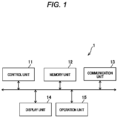
At step 102 , the representative data is received at a computer or processor 202 suitable for carrying out analysis steps according to the invention. In some embodiments, processor 202 is embodied in the same apparatus 201 used to capture the video, e.g. a mobile phone, so that only a single device is required to capture and analyse the video and display the results of the analysis.
At step 103 , the method may include the step of applying an image improvement algorithm to the video data. Such an algorithm may be used to improve the quality of the data and thereby improve the results of the analysis method. Examples of image improvement algorithms that may be used include image stabilisation algorithms, contrast enhancement algorithms, noise reduction algorithms and the like. An image stabilisation algorithm helps to reduce the effects of a camera shaking, for example if the camera is held in someone's hands, which can reduce the quality of the results obtained. A contrast enhancement algorithm may be particularly useful where light quality in the captured video is poor, which may occur, for example with video captured at a golf driving range since these are commonly in the shade. Suitable algorithms are well known in the art and will not be discussed in more detail.
At step 104 , processor 202 calculates frame difference measures for a plurality of the image frames received by the processor. In the context of this invention, frame difference measures are quantities that are indicative of differences in the video data between image frames. This step will be explained in more detail below.
At step 105 , processor 202 analyses the frame difference measures, for example by applying a decision model to the calculated frame difference measures. This step will also be explained in more detail below.
At step 106 , processor 202 outputs the results of the analysis at step 105 . In one embodiment of the invention, the analysis results comprise a plurality of image frames that each show a key position of the sports motion and the portion of the video displaying the sports motion, i.e. without any of the redundant video segments.
Key positions of the sports motion will be understood to mean any position which is considered important in the analysis of the sports motion. What those key positions are depends on the sports motion being analysed and the person involved: different people may place various degrees of significance on different positions within an individual sports motion. In the example of analysis of a golf swing, key positions are commonly considered to be the position of the golfer at address, mid-point of backswing, top of backswing, mid-point of downswing, impact and follow-through. However, these positions are mentioned by way of example only and any other position in a golf swing may be considered key. For example, a position of a sports motion may be considered to be key merely in view of the fact that it is selected for display to a user.
The portion of the video displaying the sports motion without any redundant video on either side of the motion will be often, but not always, that portion of the video between the first and last key positions. In the case of a golf swing, the relevant video portion comprises all the image frames between the frame showing the address position and the address showing the follow-through or finish position. In other embodiments, other portions of the video may be extracted as required. The start or end of the required video segment may be related to certain key positions in a particular way, for example within a certain time or number of frames from the first and last key positions.
At step 107 , the results of the analysis outputted by processor 202 are displayed on display means 203 . Display means 203 may comprise any suitable device able to display image frames and video footage, as is known in the art. In some embodiments, display means 203 is embodied in the same apparatus as processor 202 and/or video capture device 201 . For example, display means 203 may comprise the screen on a mobile phone.
At step 108 , the outputted results may be further automatically analysed and feedback provided in the form of improvement instructions. For example, in the case of a golf swing, the position of the golf club at address may be detected (discussed below). If the golf club is at too great or small an angle, this can be detected and appropriate feedback provided, e.g. (“stand nearer/further away from the ball”).
The manner in which analysis results are displayed according to some embodiments of the invention will be described below.
FIG. 3 is an illustration of a plurality of image frames 301 constituting a video 300 of a golfer according to an embodiment of the invention. The video recording is approximately 23 seconds in duration taken at 30 frames per second (fps). Only one in every five image frames are shown in FIG. 3 for convenience. During the video, the golfer made four full golf swings and the image frames showing these swings are highlighted and marked as 302 .
Video 300 is a sequence of T image frames X(t), each represented as data. Each image frame X consists of P=[n.sub.r×n.sub.c] pixels, where n.sub.r is the number of rows of pixels and n.sub.c is the number of columns of pixels in the image frame. The image frames can be represented as: X ( t )=[ x ( t ).sub.ij], where i= 1, 2, . . . , n .sub.r , j= 1, 2, . . . , n .sub.c and t= 1, 2, . . . , T.
FIG. 4 is a flow chart illustrating steps in a method 400 of analysing video data according to one, embodiment of the invention. The method 400 illustrated in FIG. 4 may be implemented in an online video analysis method.
At step 401 , T.sub.C image frames are used for analysis. T.sub.C may be equal to or less than T. In the embodiment discussed, T.sub.C=T so that all the available data is analysed. However, processing can be speeded up if only a subset of the available frames are analysed, although a sufficient number of frames must be analysed to achieve the required results. In the case of high speed video (e.g. 30 or more frames per second), not all of the image frames may need to be used for faster processing and to ensure there are sufficient changes in image between frames so that a meaningful comparison between image frames can be made.
The image frames may be processed as grey scale images of pixel intensity x, where x(t) is a member of [0, max pixel intensity]. Using grey scale simplifies the method. In other embodiments, other measures may be used, for example, colour components in a pixel.
At step 402 , the current image frame for analysis is selected. In one embodiment, the method may work sequentially through image frames in the video to be analysed. In another embodiment, the method may first work through every few frames to try to obtain results without analysing every frame, only analysing the other frames if required. In other embodiments, other ways of selecting the order of image frames, for analysis may be used.
At step 403 , the difference frame or difference image D(t) is calculated. The difference frame is the absolute difference between each of P.sub.C pixels of the current image frame X(t) and the corresponding pixels of another image frame in the past or future X(t m), where m is the number of frames before t: D ( t )=| X ( t )− X ( t−m )|.
In other embodiments, D(t) is calculated as another difference function of corresponding pixels. For example, difference image D(t) may be the squared difference, transformed difference, log of the absolute difference, difference of the logs, etc.
In some embodiments, m=±1. That is, the difference frame is based on the difference between the previous or succeeding image frame. However, m can be any integer. Integers higher than 1 may be used, for example, in the case of high speed video for faster processing and to detect greater changes in the image between frames.
In one embodiment, P.sub.C=P, that is all of the pixels in an image frame are compared to the pixels in the other image frame. However, in some embodiments, P.sub.C is less than P such that only a subset of pixels is compared in each frame or down-sampled (i.e. reduced resolution) frames are compared. This may increase efficiency, particularly in the case of high resolution imagery where adequate results can be achieved without processing all pixels. In another embodiment, pixel groups are compared between frames.
At step 404 , one or more frame difference measures are calculated. In the presently discussed embodiment, in which the image frames are comprised of pixels, the frame difference measures comprise pixel difference measures between frames or statistical values thereof. For example, at step 404 a , a difference ratio DRatio(d.sub.thres) is calculated. The difference ratio is the proportion of pixels in the difference image D that exceed a pre-determined intensity threshold d.sub.thres: D Ratio( d .sub.thres)=count([ d .sub.ij ]≧d .sub.thres)/( n .sub.r ×n .sub.c).
The difference ratio is a measure of the amount of movement in the difference image, i.e. the amount of movement between image frames. It is a global measure because it relates to the image frame as a whole (as opposed to local measures of movement at the pixel or sub-image level). A high value of DRatio(d.sub.thres) indicates large movements between frames. It is invariant against rotational transformation of images.
At step 404 b , a difference location indicator is calculated. Given a chosen intensity threshold e.sub.thres, a binary matrix E that corresponds to pixels in D that exceed e.sub.thres can be defined as: E =[ d .sub.ij]≧ e .sub.thres.
Let e.sub.h=[Σ.sub.i(e.sub.i,1) Σ.sub.i(e.sub.i,2) . . . Σ.sub.i(e.sub.i,j)] be the vector of column sum of E, and e.sub.v=[Σ.sub.j(e.sub.1,j) Σj (e.sub.2,j) . . . Σ.sub.j(e.sub.i,j)] be the vector of row sum of E. The following difference location indicators are defined as: Horizon difference location indicator: HDPrctile( p )= p th−Percentile( e .sub.h) Vertical difference location indicator: VDPrctile( p )= p th−Percentile( e .sub.v)
The horizontal and vertical difference location indicators defined above are measures of the position of movement between image frames. The value of p may be anything but may, for example, be chosen from [5, 25, 50, 75, 95] and multiple values may also be used to give more than one difference location indicator.
FIG. 5 is an illustration of the results of analysis according to one embodiment of the invention. FIG. 5 illustrates a frame 501 being analysed X(t). Frame 501 is an image of a golfer part of the way through a golf swing. The difference frame D(t) is shown in image 502 . This shows all pixels that differ between frame 501 and the comparison frame, which in this example is the immediately preceding frame. Image 503 shows the position of pixels in the difference frame exceeding a predetermined threshold e.sub.thres. Graphs 504 and 505 show the vertical and horizontal distributions respectively of the pixels in the difference frame exceeding the predetermined threshold e.sub.thres. The lines connecting graphs 504 and 505 with image 503 show the approximate positions of the 5.sup.th, 50.sup.th and 95.sup.th percentiles, i.e. three different values of each of HDPrctile(p) and VDPrctile(p) with p equal to 5, 50 and 95.
FIG. 6 is an illustration of data relating to a number of image frames calculated by a method according to one embodiment of the invention. Graph 602 is a plot of the measure of the amount of movement between image frames, DRatio, against time (or frame number). Graph 603 is a plot of the measure of the position of movement between image frames, VDPrctile(50), against time. VDPrctile
is the median of the vertical position of pixels exceeding a certain threshold in the difference frame. Note that the labels on the y-axis of graph 603 are opposite to the way the data is plotted, in fact y=0 is at the top of the graph and y=200 is at the bottom.
Referring again to FIG. 4 , the steps of analysing the frame difference measure(s) to identify key positions in the golfer's swing according to one embodiment of the invention will now be described. In this embodiment, a simple temporal recognition strategy is used. The details of the method discussed below are relevant to analysing a side view video of a golfer (as per FIG. 3 ).
At step 405 , a Gaussian filter may be applied to the temporal frame difference measure data calculated so far to reduce noise in the data.
At step 406 , swing phases are attempted to be identified in the frame difference measure data. Areas 604 , 605 and 606 show the results of identifying swing phases in the data of graphs 602 and 603 . Area 604 shows a pattern that does not represent a full swing, Areas 605 and 606 indicate the swing phases correlated to patterns in the frame difference measure data. More particularly, four distinct swing phases are identified. In FIG. 6 , these swing phases are called “start”, “up-down”, “down-up” and “end”. Each swing phase is characterised by a pattern in the frame difference measure data. For example, during the start and end phases, the value of DRatio is relatively small, indicating little overall motion. In the middle of the up-down phase DRatio and VDPrctile
hit troughs simultaneously (so in graph 603 , VDPrctile
is high since the y-axis is inverted), indicating the top of the backswing where movement is minimal and the movement position is at its highest point. During the down-up phase or downswing, DRatio is highest because body movement is at a maximum. Commonly used peak detection methods may be used to identify peaks or troughs in the data.
A complete swing must contain all 4 phases in succession. Therefore detection of the characterising pattern particular to that swing phase and a row of the 4 phases in succession is used to identify a complete swing in the data. A successful swing recognition can also be validated, for example by assessing the duration of each phase. In the case of video recording at 30 frames per second, each swing phase should be no longer than around 60 frames for most golf swings.
At decision step 407 , it is determined whether a swing has been identified. For example, detection of a swing may require the detection of all 4 swing phases to be detected in succession. If a swing has not been identified, the method loops back to step 402 , analysing the data in another image frame in the video data. If a swing has been identified, the method moves on to step 409 .
At step 408 , image frames showing key positions of the swing are identified based on the identified swing phases in the data. FIG. 7 is an illustration of part of graph 603 as shown in FIG. 6 . Graph 701 shown in FIG. 7 is a part of graph 603 including data representing the first complete swing.
Examples of how image frames showing key swing positions are identified are explained below: Address—position of the dominant peak in VDPrctile
in the start phase; Top swing—position of the dominant trough in VDPrctile
in the up-down phase; Impact—position of the dominant peak in VDPrctile
in the down-up phase; Finish—position of the dominant trough in VDPrctile
in the end phase; and Upswing and downswing—if Peak-to-Trough=dominant peak in VDPrctile
in start phase—dominant trough in VDPrctile
in up-down phase, and CrossRatio=a chosen ratio of Peak-to-Trough for determining upswing and downswing positions, then the upswing and downswing frames=first and last positions between address frame and impact frame at which VDPrctile
crosses (CrossRatio*Peak-to-Trough) above the trough, respectively. In one embodiment, CrossRatio is approximately equal to 0.3. In another embodiment, 0.5 may be chosen.
In some embodiments of the invention, object detection methods can be used to identify certain objects in the sports motion and, optionally, use the object detection to help or validate identification of swing phases and/or key positions. In the case of golf swing analysis, golf club detection methods can be used, for example straight line detection algorithms.
Referring again to FIG. 6 , graph 601 shows the result of peak angle detection in a Hough transform of the image frames. That is, the data in graph 601 is representative of the angle of the golf club in the image frames. In alternative embodiments, Radon transforms or any other suitable algorithm may be used. The most accurate identification of club angle and position can be made at the address and finish positions where the club is relatively stationary.
At step 409 in FIG. 4 , the image frames in which the key swing positions are shown are output. FIG. 8 is an illustration of images showing key swing positions when a method according to an embodiment of the invention is applied to the video data shown in FIG. 3 . For each of the four swings in the recorded video, six key positions are provided. In the embodiment shown, an object detection algorithm has been applied to indicate the position of the golf club at address. This is shown by a line in all the frames.
At step 410 , the portion of the initially recorded video showing the golf swing(s) is outputted. This is output in the form of video data comprising the image frames between the address and finish position, and may also comprise a few image frames either side of these positions if desired. In the case of the video shown in FIG. 3 , there would be four short video segments outputted, each showing one of the swings recorded.
Only outputting the key position frames and not the extracted golf swing segments may be advantageous because of a reduction in memory requirements and processing speed.
After step 410 , the method may return to step 402 to continue analysing the video for any more swings that may be present.
It should be noted that some of the method steps of the invention may occur simultaneously or in different order. The steps of FIG. 4 are shown one after the other for explanatory purposes only. By performing some steps of the method simultaneously as appropriate, the method of the invention is able to cater for “real time” operation, or at least very short processing times.
FIG. 9 is an illustration of images showing key swing positions according to another embodiment of the invention. FIG. 9 shows key swing positions of an “expert's” swing 901 and these are aligned with equivalent key swing positions from three swings by a subject 902 . Displaying image frames in this way is extremely useful for the subject to compare their swing with that of an expert.
The description continues in the full USPTO document.
 Lapsed, fee not paid11 drawings