 Lapsed, fee not paid3 drawings
Cameras, Displays & Optics · US 9,743,027 B2
Image sensor with high dynamic range and method
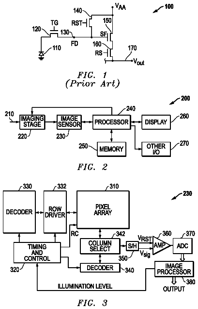
In one form, a pixel for use in image sensing comprises a photodetector, a sink device, and a readout circuit.
US 9,743,031 B2 · Assignee: FUJIFILM Corporation · Inventors: Endo; Hiroshi
Sheet 1 of 12 from the published document. All sheets in the USPTO PDF
This imaging device is equipped with an interchangeable optical system, and includes: a sensor section that has a configuration allowing nondestructive reading of a signal from each pixel; a reading section that reads a signal from the sensor section in a nondestructive manner for each pixel; a signal storage section that is able to add up and store the signals for each pixel; and a correction control section that acquires shading characteristics and controls the reading section and the signal storage section. Each pixel has an organic layer that includes a photoelectric conversion layer. On the basis of the shading characteristics, the correction control section sets the number of operations of signal reading of peripheral pixels such that the number is greater than the number of operations of signal reading of central pixels, and generates image data from the signal of each pixel stored in the signal storage section.
In some cases, luminance unevenness (shading) may occur between a central portion and a peripheral portion of an image, which is captured by an imaging device such as a digital camera, due to characteristics of an optical system (such as a lens). Accordingly, there have been proposed various methods for correcting shading. For example, JP2006-115191A discloses an imaging device including: accumulation start control means for controlling start of photoelectric charge accumulation of an imaging element; and accumulation end control means for controlling end of the accumulation of the imaging element by transmitting the photoelectric charge of the light receiving portion to a temporary accumulation section. In this imaging device, control timing of the accumulation start control means and/or the accumulation end control means is changed for each pixel or for each line, and a time period of
1 of 12 drawing sheets so far from the published document, cropped to the drawing. Every sheet is in the USPTO PDF.
What the patent claimed, word for word. All of it is now free to use.
The present invention relates to an imaging device and an imaging method, and particularly relates to a shading correction technology.
In some cases, luminance unevenness (shading) may occur between a central portion and a peripheral portion of an image, which is captured by an imaging device such as a digital camera, due to characteristics of an optical system (such as a lens). Accordingly, there have been proposed various methods for correcting shading.
For example, JP2006-115191A discloses an imaging device including: accumulation start control means for controlling start of photoelectric charge accumulation of an imaging element; and accumulation end control means for controlling end of the accumulation of the imaging element by transmitting the photoelectric charge of the light receiving portion to a temporary accumulation section. In this imaging device, control timing of the accumulation start control means and/or the accumulation end control means is changed for each pixel or for each line, and a time period of accumulating photoelectric charge for each pixel or for each line is controlled, thereby correcting shading of a captured image.
JP-S64-039178A discloses an imaging device including an image sensor that is configured to perform photoelectric conversion on an optical image and perform nondestructive reading. In this imaging device, light signals of a single frame are read from the image sensor multiple times, and are sequentially added up, and an integrated output signal is output when the number of adding operations reaches a predetermined number. Thereby, a limitation of a Signal-Noise ratio (SN ratio) of an amount of light incident into the image sensor is improved, and thus high sensitivity is achieved.
In addition to the shading correction, there are proposed various imaging processing methods for improving image quality of a captured image.
For example, JP2008-271368A discloses an imaging device including: an imaging section that outputs a captured image signal formed of a long-exposure image signal and a short-exposure image signal; and a signal processing section that generates a synthesized image signal in which the long-exposure image signal and the short-exposure image signal are synthesized and which has a wide dynamic range. In this imaging device, exposure control is performed in accordance with a user setting exposure mode, and automatic exposure control for the short-exposure image signal is performed using luminance information of the synthesized image signal. Thereby, a problem of white color in the setting exposure mode is solved.
JP2011-243704A discloses a solid-state imaging device in which a gate electrode of the signal reading circuit includes a signal conversion transistor and the signal conversion transistor is connected to a photoelectric conversion section. This photoelectric-conversion-film-laminated-type solid-state imaging device prevents noise from being mixed with the signals at the time of electric charge accumulation.
In the conventional shading correction, by achieving an increase in gain of the signals (pixel values) of the pixels within the peripheral portion (an increase in amplification ratio), a decrease in amount of light in a peripheral portion is canceled out. Thereby, a problem of luminance unevenness occurring between a central portion and the peripheral portion of an image is solved.
However, since the increase in gain of the pixel values also causes an increase in noise components, in an image subjected to shading correction based on the gain control of the pixel values, image quality is lowered by the increased noise components. Accordingly, it is preferable that shading correction for suppressing deterioration in image quality is performed by suppressing the increase in noise components. In particular, in an interchangeable-lens-type imaging device, a lens (optical system) having various characteristics is mounted on a main body. Hence, it is preferable to apply shading correction flexibly compatible with various shading characteristics.
However, in conventional technologies such as JP2006-115191A, JP1989-039178A (JP-H01-039178A), JP2008-271368A, and JP2011-243704A mentioned above, it is difficult to achieve such shading correction. For example, in the imaging device described in JP2006-115191A, a photoelectric charge accumulation time period (exposure time period) is controlled. However, if the photoelectric charge accumulation time period is long, image blurring is noticeable, and image quality deteriorates. Likewise, even in the imaging device described in JP2008-271368A, if the exposure time period is long, image blurring is noticeable, and image quality deteriorates. Further, in JP1989-039178A (JP-S64-039178A) and JP2011-243704A, deterioration in image quality caused by shading is not considered at all.
The present invention has been made in consideration of the above-mentioned situation, and its object is to provide an image processing technology for achieving shading correction for suppressing deterioration in image quality caused by the increase in noise components and an image processing technology which can be flexibly applied to optical systems having various shading characteristics.
According to an aspect of the present invention, there is provided an imaging device that generates image data of an image of received light, the imaging device including: a sensor section that includes a plurality of pixels generating signals corresponding to the light received through the interchangeable optical system and that has a configuration allowing nondestructive reading of the signals generated by the plurality of pixels; a reading section that reads the signals of the respective pixels from the sensor section in a nondestructive manner; a signal storage section that is able to add up and store the signals of the respective pixels which are read by the reading section; and a control section that acquires shading characteristics of the optical system and controls the reading section and the signal storage section, in which each of the plurality of pixels has a color filter and an organic layer including a photoelectric conversion layer which generates electric charge corresponding to light received through the color filter, and in which the control section sets a ratio of a number of operations for reading the signals of a pixel within a central portion among the plurality of pixels to a number of operations for reading the signals of a pixel within a peripheral portion, on the basis of the shading characteristics, performs the setting such that the number of operations for reading the signals of the pixel within the peripheral portion is greater than the number of operations for reading the signals of the pixel within the central portion, and generates the image data from the signals of the respective pixels stored in the signal storage section.
According to the present aspect, the number of operations for reading the signals is set on the basis of the shading characteristics, and the image data is generated from the signals of the respective pixels stored in the signal storage section. Thus, it is possible to prevent image quality from deteriorating due to shading while preventing noise components from increasing. Further, the shading characteristics as a basis of the setting of the number of operations for reading the signals can be acquired in accordance with an interchangeable optical system. Thus, the shading correction technology according to the present aspect can be flexibly applied to various optical systems.
The imaging device of the present aspect is appropriate for so-called interchangeable-lens-type digital cameras and the like.
The “nondestructive reading” is a method of reading signals basically in a state where the signals (electric charge) of target pixels can be read repeatedly no matter how many times the reading is repeated. In this method, after the signal reading, electric charge, which can be stored in the target pixels, can be continuously held in the target pixels without being discharged. A specific configuration of a nondestructively readable sensor section is not particularly limited. For example, the following configuration may be made: each pixel has a capacitor for accumulating electric charge and electric charge held in the capacitor can be read repeatedly no matter how many times the reading is repeated. As such “a sensor section having the nondestructively readable configuration”, for example, a complementary-metal-oxide-semiconductor (CMOS) type imaging element can be appropriately used. In particular, a CMOS-type imaging element having an organic layer according to the present aspect is also called “an organic CMOS sensor”, has a high dynamic range, high sensitivity, and a wide light incidence area, and contributes to an increase in sensitivity of the sensor section, an increase in image quality, and a decrease in size.
The “shading characteristics of the optical system” is an arbitrary indicator which represents shading caused in accordance with the optical system, and can be represented by a data format which directly or indirectly indicates light attenuation distribution (luminance unevenness) based on shading.
The “pixel within the central portion” and the “pixel within the peripheral portion” can be appropriately set in consideration of the effect of luminance unevenness caused by shading, on the basis of a relative position relationship. Accordingly, the “pixel within the central portion” does not necessarily mean only “a single pixel (central pixel) at the center”, and “the pixel within the central portion” may mean “the central pixel and a plurality of pixels around the pixel” which are less affected by the light attenuation caused by shading. Further, “the pixel within the peripheral portion” may mean pixels, which are more affected by the light attenuation caused by shading, among pixels (pixels positioned at relatively large distances from the central pixel) having relatively high image heights.
Preferably, the control section adds the signals of the pixel within the central portion for each of the pixels which are read multiple times, stores the signals in the signal storage section, and generates the image data from the signals of the respective pixels stored in the signal storage section.
According to the present aspect, the signals of the pixel within the central portion are also read multiple times, and are added and stored, thereby generating image data from the added and stored signals of the respective pixels. As a result, it is possible to suppress and reduce the effect of noise included in the signals of the pixel within the central portion.
Preferably, in the image data, data of each pixel within the central portion is based on an arithmetic mean value of the signals stored in the signal storage section, and data of each pixel within the peripheral portion is based on a sum of the signals stored in the signal storage section.
According to the present aspect, data of the pixel within the central portion can be acquired on the basis of the arithmetic mean value of the signals, and thus it is possible to reduce the effect of noise. Further, the data of the pixel within the peripheral portion can be acquired on the basis of the sum of the signals, and the number of adding operations is set in accordance with the shading characteristics. Thus, it is possible to reduce the effect of shading.
Preferably, the reading section is able to read the signals from only the pixel within the peripheral portion when reading the signals from the pixel within the peripheral portion.
According to the present aspect, when the signals are read from the pixel within the peripheral portion, it is not necessary to read signals from the pixel within the central portion. Thus, it is possible to prevent heat (noise) from occurring due to the reading of the signals.
As the sensor section capable of “reading signals from only the pixel within the peripheral portion”, for example, a CMOS-type imaging element can be appropriately used.
Preferably, the control section acquires the shading characteristics from a lens characteristics storage section which stores the shading characteristics of the optical system.
According to the present aspect, it is possible to acquire the shading characteristics of the optical system from the lens characteristics storage section. It should be noted that the lens characteristics storage section can be arbitrarily disposed such that the control section is accessible thereto. For example, the lens characteristics storage section may be provided together with the optical system or the control section, and the lens characteristics storage section may be provided on an external device.
Preferably, the control section acquires the shading characteristics on the basis of the signals each of which is read from the sensor section for each pixel.
According to the present aspect, the shading characteristics of the mounted optical system can be acquired on the basis of the signals of the sensor section. Hence, even when an optical system of which shading characteristics are unclear is mounted, it is possible to acquire the shading characteristics of the optical system.
Preferably, the imaging device further includes a user interface, in which the control section controls the user interface such that the user interface prompts a user to capture an image for calculation of the shading characteristics, and calculates the shading characteristics on the basis of the image data of the image for calculation of the shading characteristics.
According to the present aspect, on the basis of an image for calculation of shading characteristics captured by a user, it is possible to acquire the shading characteristics of the optical system.
As this “image for calculation of shading characteristics”, it is possible to use an arbitrary captured image. For example, as the “image for calculation of shading characteristics”, a live view image or the like may be used.
Preferably, the control section reads the signals of a plurality of frames from the sensor section, and acquires the shading characteristics on the basis of the arithmetic mean values of the signals of the plurality of frames.
According to the present aspect, it is possible to precisely acquire shading characteristics on the basis of the arithmetic mean values of the signals corresponding to the plurality of frames.
The “signals corresponding to the plurality of frames” described herein are “signals constituting a plurality of images”. The signals constituting each frame (each image) may be signals obtained from all pixels of the sensor section, and may be signals obtained from some pixels of the sensor section. However, it is preferable that the “signals corresponding to the plurality of frames” include the signals obtained from all pixels of the sensor section. For example, by adding the signals of the live view image having the plurality of frames and taking an arithmetic mean thereof, it is also possible to calculate the shading characteristics of the optical system.
According to another aspect of the present invention, there is provided an imaging method of generating image data of an image of light received through an imaging device including a sensor section that includes a plurality of pixels generating signals corresponding to the light received through an interchangeable optical system and that has a configuration allowing nondestructive reading of the signals generated by the plurality of pixels, a reading section that reads the signals of the respective pixels from the sensor section, and a signal storage section that is able to add up and store the signals of the respective pixels which are read by the reading section, the imaging method including: a step of acquiring shading characteristics of the optical system; a step of reading the signals from the sensor section and storing the signals in the signal storage section; and a step of generating the image data from the signals of the respective pixels stored in the signal storage section, in which each of the plurality of pixels has a color filter and an organic layer including a photoelectric conversion layer which generates electric charge corresponding to received light, and in which a ratio of a number of operations for reading the signals of a pixel within a central portion among the plurality of pixels to a number of operations for reading the signals of a pixel within a peripheral portion is set on the basis of the shading characteristics, and the setting is made such that the number of operations for reading the signals of the pixel within the peripheral portion is greater than the number of operations for reading the signals of the pixel within the central portion.
According to the present invention, the number of operations for reading the signals is set on the basis of the shading characteristics, and the image data is generated from the signals of the respective pixels stored in the signal storage section. Thus, it is possible to prevent image quality from deteriorating due to shading while preventing noise components from increasing.
Further, the shading characteristics as a basis of the setting of the number of operations for reading the signals can be acquired in accordance with an interchangeable optical system. Thus, the present invention can be flexibly applied to various optical systems.
FIG. 1A is a diagram illustrating an example of an image for explaining shading.
FIG. 1B is a plan view illustrating an imaging element (pixels).
FIG. 2 is a graph illustrating an example of a relationship between a luminance (light intensity) of an image and an image height before and after the shading correction.
FIG. 3 is a perspective view of an imaging device according to an embodiment of the present invention as viewed obliquely from the front.
FIG. 4 is a rear view of the imaging device shown in FIG. 3 .
FIG. 5 is a block diagram illustrating a configuration example of an imaging device (digital camera).
FIG. 6 is a sectional view illustrating a configuration example of the imaging element, and shows some of a plurality of pixels (3 pixels) constituting the imaging element.
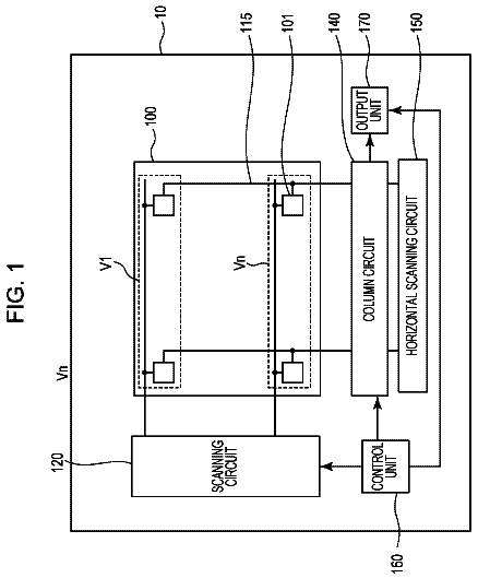
FIG. 7 is a circuit diagram of the imaging element, and shows circuit configuration examples of mainly a sensor section (a common electrode, an organic layer, and an individual electrode) and a reading section for reading the signals for each pixel from the sensor section in a nondestructive manner.
FIG. 8 is a diagram illustrating configuration examples of the imaging element and peripheral circuits thereof.
FIG. 9 is a block diagram illustrating a configuration of an image processing section (shading correction section) of a main body controller.
FIG. 10 is a flowchart illustrating a flow of shading correction processing.
FIG. 11 is a flowchart illustrating a flow of processing of acquiring shading characteristics of an optical system.
FIG. 12 is a flowchart illustrating an image processing process according to the first embodiment.
FIG. 13 is a flowchart illustrating an image processing process according to the second embodiment.
FIG. 14 is a flowchart illustrating an image processing process according to the third embodiment.
FIG. 15 is a flowchart illustrating an image processing process according to the fourth embodiment.
FIG. 16 is a diagram illustrating an appearance of a smartphone as an embodiment of an imaging device.
FIG. 17 is a block diagram illustrating a configuration of the smartphone shown in FIG. 16 .
FIG. 1A is a diagram illustrating an example of an image for explaining shading. FIG. 1B is a plan view illustrating an imaging element (pixels). In FIG. 1A , the contrasting density represents contrast in the image I, where the less dense part (white part) is lighter, and the more dense part (black part) is darker. FIG. 1B shows only some of a plurality of pixels 40 of an imaging element (image sensor) 26 , but the pixels 40 are two-dimensionally arranged to be continuously adjacent. FIG. 2 is a graph illustrating an example of a relationship between a luminance (light amount ratio) of an image and an image height before and after the shading correction. The X axis of FIG. 2 indicates an “image height” (a distance from the image center), and the “O” of FIG. 2 indicates an image center position (image height=0). In contrast, the Y axis of FIG. 2 indicates a “light amount ratio” which is obtained by normalizing an amount of light for each image height of a captured image on the basis of a predetermined value (for example, an amount of light at the center position of the image).
The shading is a phenomenon that a degree of light attenuation according to the photography optical system changes in accordance with the image height due to optical characteristics of a photography optical system (lens section). Generally, a peripheral portion of a captured image becomes darker than a central portion (refer to “C” indicated by the dotted line of FIG. 1A ) thereof. Shading correction is image processing for solving brightness unevenness (luminance unevenness) of the image caused by the shading. In addition, the shading correction is processing for increasing the brightness of the peripheral portion of the image on the basis of the brightness of the central portion of the image.
The shading changes depending on characteristics of the photography optical system. Thus, in accordance with the optical system used in actual photography, there are various degrees and appearances of the luminance unevenness caused by the shading. Accordingly, in order to perform shading correction appropriate for an image captured by an interchangeable-lens-type imaging device, it is necessary to detect shading characteristics of the optical system (interchangeable lens) used in actual photography and adjust the brightness of the image on the basis of the shading characteristics.
As a result of a keen examination, instead of the conventional method of increasing the signal gain of the peripheral pixels, the inventors newly found a method of summing up signals which are read by performing nondestructive reading multiple times on the signals from the peripheral pixels of the imaging elements, through a single exposure processing operation (a single process of image photography acquisition processing), using a nondestructively readable imaging element. The numbers (ratio) of operations for adding (summing up) the signals and operations of nondestructive reading from the central and peripheral pixels can be set in accordance with the shading characteristics of the photography optical system. Thus, the number of operations for adding the signals and the number of operations of nondestructive reading from the central pixels are set to be larger than those of the central pixels. Thereby, it is possible to precisely perform shading correction by achieving balance in brightness (luminance) between the peripheral and central portion of the image.
By reading the signals from the peripheral pixels multiple times and summing up the signals, pixel data of the peripheral pixels is obtained. In such a manner, noise components in the peripheral portion of the image are suppressed and reduced. Thereby, it is possible to obtain an image with high image quality. That is, when the signals (electric charge) are read n times from the imaging element and integrated (added), the magnitudes of the signals becomes n times, while random noise (such as amplifier noise) is reduced. Thus, the SN ratio is improved as a whole. In particular, the imaging element having an organic thin film and a capacitor may be used, and noise (such as noise caused by thermal excitation) mixed with electric charge (electrons) accumulated in the capacitor of each pixel may be small enough to be negligible. In this case, the main component of the noise becomes amplifier noise, and thus the effect of noise suppression performed by reading the signals multiple times and summing up the signals is further improved. Further, by adopting a method of reading pixel signals in a nondestructive manner and a method of integrating the signals, it is possible to effectively prevent image quality from being deteriorated by shading without increasing noise in a short exposure time period.
It should be noted that the method of reading the signals (electric charge) from the respective pixels of the imaging element includes a “destructive reading method” and a “nondestructive reading method”. In the destructive reading method, one electric charge is read from each target pixel, electric charge stored in the pixel is discharged (reset), and the electric charge (signal) stored until the reading cannot be read again from the target pixel. In contrast, in the nondestructive reading method, the electric charge stored in the target pixel can be repeatedly read basically no matter how many times the reading is repeated. For example, by adopting a configuration in which the capacitor for accumulating the electric charge is provided for each pixel and the electric charge held in the capacitor can be read multiple times not matter how many times the reading is repeated, it is possible to implement the nondestructive reading method.
Further, the inventors of the present invention found the following fact. The effect of improving image quality through shading correction is enhanced by combining the above-mentioned shading correction technology and the nondestructive reading imaging element formed by not silicon photodiodes but light receiving portions having an “organic thin film”.
The silicon photodiode is characterized in that ray angle dependency of the intensity of the obtained signal is relatively high and an angle of received light is limited. Accordingly, the effect of shading in the image captured by the CMOS sensor having the silicon photodiodes changes in accordance with combination between the imaging element (silicon photodiode) and the photography optical system. Hence, in order to precisely correct shading of the image captured by the imaging element using the silicon photodiodes, it is necessary to perform shading correction in which characteristics of both the photography optical system and the imaging element are reflected.
In contrast, the organic thin film, of which a light absorption coefficient is large, is characterized in that ray angle dependency of the intensity of the obtained signal is excessively small and an angle of received light is wide. Accordingly, the effect of shading in the image captured by the imaging element (such as the organic CMOS sensor) having the organic thin film primarily depends on characteristics of the photography optical system. Thus, it is possible to perform effective shading correction on the basis of only the characteristics of the photography optical system without consideration of sensor characteristics. In addition, even when the organic CMOS sensor is used, it is possible to perform shading correction by increasing the signal gain of the peripheral pixels such that the gain is greater than that of the central pixels. Even in this case, the gain value can be determined on the basis of only the shading characteristics of the photography optical system.
In addition, in the past, a technology, in which luminance shading of the image captured by the above-mentioned organic CMOS sensor is considered, and a shading correction technology, which uses characteristics of an organic CMOS sensor to be described later, have not been proposed.
Hereinafter, an interchangeable-lens-type imaging device according to the above-mentioned shading correction technology will be described.
FIG. 3 is a perspective view of an imaging device (digital camera) according to an embodiment of the present invention as viewed obliquely from the front. FIG. 4 is a rear view of the imaging device shown in FIG. 3 .
The imaging device 1 of the present example includes a camera main body 10 and an interchangeable lens unit 12 (optical system) that is detachably mounted on the camera main body 10 , and generates image data of an image of received light of a subject.
A mount 10 - 1 on which the interchangeable lens unit 12 is mounted, a finder window 10 - 2 of an optical finder, and the like are provided on the front of the camera main body 10 . A shutter release button 10 - 3 , a shutter speed dial 10 - 4 , an exposure correction dial 10 - 5 , and the like are provided on the upper surface of the camera main body 10 . An eyepiece section 10 - 6 of the optical finder, a MENU/OK button 10 - 7 , an arrow key 10 - 8 , a liquid crystal monitor 10 - 9 , and the like are provided on the rear surface of the camera main body 10 .
The liquid crystal monitor 10 - 9 functions as an image display section that displays a captured image (such as a live view image in a photography mode and a captured image in a reproduction mode), and functions as an operation instruction display section that displays various menu screens. The MENU/OK button 10 - 7 is an operation section having both a function as a menu button to give a command to display a menu screen on the liquid crystal monitor 10 - 9 and a function as an OK button to give a command to confirm and execute selected contents. The arrow key 10 - 8 is an operation section to input instructions of four directions of up, down, right, and left, and functions as a button that gives an instruction to select various setting items from the menu screen displayed on the liquid crystal monitor 10 - 9 . Further, the up/down key of the arrow key 10 - 8 functions as a zoom switch at the time of photography or a reproduction zoom switch in the reproduction mode, and the right/left key functions as a frame advance (forward-direction/opposite-direction advance) button in the reproduction mode.
FIG. 5 is a block diagram illustrating a configuration of the entirety of the information processing apparatus 1 . The camera main body 10 and the interchangeable lens unit 12 of the imaging device 1 are electrically connected through a camera main body input/output section 30 of the camera main body 10 and a lens unit input/output section 22 of the interchangeable lens unit 12 , and are able to transmit and receive signals.
The interchangeable lens unit 12 has an optical system including a lens 16 , a diaphragm 17 , and the like, and an optical system operation section 18 that controls the optical system. The optical system operation section 18 includes a lens unit controller 20 connected to the lens unit input/output section 22 and an actuator (not shown in the drawing) that operates the optical system.
The lens unit controller 20 controls the optical system (such as the lens 16 and the diaphragm 17 ) through the actuator on the basis of control signals sent from the camera main body 10 through the lens unit input/output section 22 , and performs, for example, focus control and zoom control based on lens movement, aperture amount control of the diaphragm 17 , and the like. Further, the lens unit controller 20 transmits characteristics of the optical system to the camera main body 10 in response to the control signal (request command) which is sent from the camera main body 10 (main body controller 28 ) through the lens unit input/output section 22 .
The lens unit memory 24 holds data of characteristics of the interchangeable lens unit 12 , and the lens unit controller 20 sends the data of the characteristics held in the lens unit memory 24 to the main body controller 28 of the camera main body 10 . In particular, the lens unit memory 24 of the present example holds various types of data indicating the shading characteristics of the interchangeable lens unit 12 (optical system), and data of the shading characteristics is transmitted from the lens unit memory 24 to the main body controller 28 as necessary.
On the other hand, the camera main body 10 includes an imaging element 26 , the main body controller 28 , a camera main body input/output section 30 , an input/output interface 32 , a user interface 34 , and the like.
The imaging element 26 includes a plurality of pixels 40 (refer to FIG. 1B ), and each pixel has a color filter of RGB of the like and an image sensor. Each pixel 40 generates an electrical signal in response to light which is received through the optical system (such as the lens 16 and the diaphragm 17 ) of the interchangeable lens unit 12 , and sends an image signal (original image data) to the main body controller 28 . The imaging element 26 of the present example is formed by an organic CMOS sensor. Each pixel 40 has a color filter and an organic layer that includes a photoelectric conversion layer generating electric charge in response to the light received through the color filter. The imaging element has a configuration allowing nondestructive reading of the electric charge (signal) generated by each pixel 40 . A specific configuration of the imaging element 26 will be described later.
The input/output interface 32 is a section that relays interchange of information between the imaging device 1 (the camera main body 10 and the main body controller 28 ) and external devices (such as a computer, a server, and a mobile device). For example, various types of data of the imaging device 1 (the camera main body 10 and the interchangeable lens unit 12 ) and image data before and after image processing are transmitted and received between the imaging device 1 and the external devices through the input/output interface 32 . In addition, an aspect of connection of the external devices to the input/output interface 32 is not particularly limited. For example, both wired connection and wireless connection may be used.
A format of image data, which is sent from the imaging device 1 (main body controller 28 ) to the external devices, is not particularly limited, and may be an arbitrary format such as a RAW, a joint photographic coding experts group (JPEG), a tagged image file format (TIFF), or the like. Consequently, the main body controller 28 may associate a plurality of related data pieces with each other so as to form a single image file, and may transmit the image file to the external devices. The related data pieces include, like so-called exchangeable image file format (Exif), header information (photography information (photography date and time, a device type, a pixel number, an aperture value, and the like) and the like), main image data, and thumbnail image data, and the like.
The user interface 34 is a section that relays interchange of information between a user and the imaging device 1 (the camera main body 10 and the main body controller 28 ), and for example, performs various displays for the user or receives an instruction from the user. For example, the respective sections (such as the finder window 10 - 2 , the shutter release button 10 - 3 , the shutter speed dial 10 - 4 , the exposure correction dial 10 - 5 , the eyepiece section 10 - 6 , the MENU/OK button 10 - 7 , the arrow key 10 - 8 , and the liquid crystal monitor 10 - 9 ) shown in FIGS. 3 and 4 function as the user interface 34 .
The main body controller 28 integrally controls the imaging device 1 , thereby functioning as a device control section that controls various devices of the camera main body 10 and the interchangeable lens unit 12 , and functioning as an image processing section that performs various kinds of image processing on the image captured by the imaging element 26 . The main body controller 28 performs various kinds of control (such as photography control, image processing control, image data recording/reproduction control, control of display of an image (live view image), and control of display of a liquid crystal monitor (LCD: Liquid Crystal Display)), on the basis of an operation signal sent from a user through the user interface 34 and an operation signal sent from the external devices through the input/output interface 32 .
Accordingly, the main body controller 28 controls, for example, an output of the image signals sent from the imaging element 26 , generates a control signal for controlling the interchangeable lens unit 12 and transmits the signal to the interchangeable lens unit 12 (lens unit controller 20 ) through the camera main body input/output section 30 , and transmits image data before and after image processing to the external devices connected through the input/output interface 32 . Further, the main body controller 28 performs arbitrary image processing on the image signals sent from the imaging element 26 as necessary. For example, the main body controller 28 appropriately performs various kinds of image processing such as sensor correction processing, demosaic (synchronization) processing, pixel interpolation processing, color correction processing (offset correction processing, white balance processing, color matrix processing, gamma conversion processing, and the like), RGB image processing (sharpness processing, tone correction processing, exposure correction processing, outline correction processing, and the like), RGB/YCrCb conversion processing, and image compression processing. In particular, the main body controller 28 of the present example performs shading correction on the image signals (original image data) as described later. The shading correction will be described in detail.
The main body controller 28 has an AE detection section and an AF detection section (not shown in the drawing), and performs automatic exposure (AE) processing and auto focus (AF) processing.
When the shutter release button 10 - 3 is pressed down to a first stage (pressed halfway), an AE operation is started. Then, the main body controller 28 sends the image signals (digital signals) from the imaging element 26 to the AE detection section. The AE detection section sums up the digital signals corresponding to the entire screen, or sums up the digital signals which are differently weighted between the screen central portion and the peripheral portion. The main body controller 28 calculates a brightness (photography exposure value (EV)) of a subject from the value of summation, and determines an aperture value (F number) and an electronic shutter (shutter speed) on the basis of the photography EV value, in accordance with a predetermined program diagram. The main body controller 28 controls the diaphragm 17 on the basis of determined aperture value, and controls a time period of electric charge accumulation in the imaging element 26 on the basis of the determined shutter speed. Meanwhile, the AF detection section is able to calculate a value, which is obtained through the summation, as an AF evaluation value by summing up absolute values of high-frequency components of the digital signals which are received when the shutter release button 10 - 3 is pressed halfway and correspond to an AF area. The main body controller 28 moves a focus lens (not shown in the drawing) of the interchangeable lens unit 12 toward the infinity, searches for an in-focus position at which the AF evaluation value is at the maximum, and moves the focus lens to the in-focus position, thereby being able to perform focus adjustment on a subject (main subject).
The description continues in the full USPTO document.
About 6,385 words. The USPTO PDF has it with every drawing.
Fees are due 3.5, 7.5 and 11.5 years after grant. This patent expired on August 22, 2025, so the fee marked "not paid" was the one that went unpaid.
IMAGING DEVICE AND IMAGING METHOD
Filed Feb 2016 · published Jun 2016Imaging device and imaging method
Filed Feb 2016 · granted Aug 2017Earlier publications, parents and continuations. None of them can still be enforced, or this patent would not be listed.
Prior art cited by the examiner or applicant. Useful when you check your own idea for novelty.
Everything on this page comes from the documents linked above.