Background of the invention
1. Field of the invention
The present invention relates to a plane illumination apparatus and a backlight apparatus that use a light source for emitting coherent light beams.
2. Description of related art
As a backlight apparatus used in liquid crystal panels or the like, a system in which light is incident on an edge of a light guide plate, repeatedly reflected between two opposing surfaces by total reflection, and then taken out by a diffusion device or the like is known. This type of backlight apparatus includes backlight apparatuses using a cold cathode fluorescent lamp as a light source and also, recently, backlight apparatuses using an LED as a light source.
When a cold cathode fluorescent lamp is used, there is a problem in that it is difficult to make a backlight apparatus thin and power consumption increases. When an LED is used, although it is possible to make a backlight apparatus thin, since an LED is a uniform diffusion illumination device, it is difficult to make every light incident on a thin light guide plate with no leakage, hence loss is caused.
In contrast to above, a laser beam is excellent in straightness, and hence considered to improve light incidence efficiency.
However, when a laser beam is used as a light source, speckles due to high coherency of laser are generated. Speckles are a spotted pattern which is formed when a coherent light beam such as a laser beam is emitted to a scattering plane. If speckles are generated on a screen, they are observed as spotted luminance unevenness, i.e. brightness unevenness, thus becoming a factor of having physiologically adverse affect on an observer. It is considered that the reason why speckles are generated in the case of using coherent light beams is that coherent light beams reflected from respective portions of a scattering and reflecting plane such as a screen have very high coherency so that coherent light beams interfere with one another to generate speckles. For example, a theoretical review of the generation of speckles is made in detail in Speckle Phenomena in Optics, Joseph W. Goodman, Roberts & Co., 2006.
As discussed above, in the system using a coherent light source, since there is a problem of generation of speckles unique to the coherent light source, techniques for suppressing the generation of speckles have been proposed. For example, Japanese Patent Laid-Open No. 6-208089 discloses a technique in which a laser beam is emitted to a scattering plate, scattered light beams obtained therefrom are guided to a spatial light modulator, and the scattering plate is driven to rotate by a motor, thus reducing speckles.
Summary of the invention
Not only backlight apparatuses, speckles are problems in a variety of apparatuses having an illumination apparatus for illuminating an illumination zone with coherent light beams. Coherent light beams, for example laser beams as a typical example, show excellent straightness and can emit a light of extremely high energy density. Therefore, it is preferable for illumination apparatuses actually developed to design the optical path of coherent light beams in accordance with the characteristics of coherent light beams.
The inventors have extensively researched under consideration of the points discussed above, and as a result, the inventors have contrived the invention regarding a plane illumination apparatus and a backlight apparatus which illuminate a specific zone repeatedly with coherent light beams that are then diffused and taken out to the outside with speckles made inconspicuous. Moreover, the inventors have proceeded with researches and succeeded in improvement in the illumination apparatus to constantly prevent the generation of a region extremely bright in a specific zone illuminated with coherent light beams. Namely, the purpose of the present invention is to provide a plane illumination apparatus and a backlight apparatus that are capable of making speckles inconspicuous and effectively suppressing the generation of brightness unevenness in a specific zone.
In order to solve the problems above, according to an aspect of the present invention, there is provided a plane illumination apparatus comprising:
an optical device configured to be capable of diffusing coherent light beams from respective points to an entire region of the corresponding areas in a specific zone;
an irradiation unit configured to irradiate the coherent light beams to the optical device so that the coherent light beams scan a surface of the optical device; and
a light guide plate configured to make coherent light beams that are reflected at a surface of the optical device or that have passed through the optical device propagate and to comprise a light take-out surface from which the coherent light beams are taken out to outside,
wherein the irradiation unit makes the coherent light beams scan the surface of the optical device by changing propagation directions of the coherent light beams,
the light guide plate comprises a light take-out portion configured to take out coherent light beams to outside while making coherent light beams propagate between a first end face on which coherent light beams from the optical device are incident and a second end face that is provided to face the first end face,
the specific zone is provided inside the light take-out portion or along the first end face, or along the second end face,
the light take-out surface is a third end face that is connected to the first and second end faces, and
the irradiation unit is provided at a rear side of a fourth end face that is an opposite side to the light take-out surface of the light take-out portion.
According to the present invention, it is possible to provide a plane illumination apparatus and a backlight apparatus that are capable of making speckles inconspicuous and effectively suppressing the generation of brightness unevenness in a specific zone.
Brief description of drawings
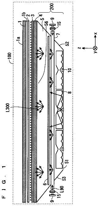
FIGS. 1( a ) and 1( b ) are views showing a schematic configuration of a plane illumination apparatus according to an embodiment of the present invention;
FIGS. 2( a ) and 2( b ) are views showing a schematic configuration of a plane illumination apparatus according to a modification of FIGS. 1( a ) and 1( b ) ;
FIG. 3 is a view explaining the operational principle of an illumination apparatus 40 of FIGS. 1( a ) and 1( b ) ;
FIG. 4 is a view explaining a state in which an image of a scattering plate is formed on a hologram recording medium 55 as interference fringes;
FIG. 5 is a view explaining a state in which an image of a scattering plate is reproduced using interference fringes generated in the hologram recording medium 55 obtained through an exposure process of FIG. 4 ;
FIG. 6 is a view explaining a scanning route of a scanning device 65 ;
FIG. 7 is a view showing results of measuring speckle contrasts in the cases where the hologram recording medium 55 was used and not used;
FIG. 8 is a view showing an example of an irradiation unit provided with a scanning device rotatable in two axes directions; and
FIG. 9 is a view showing an example of making a parallel beam incident on the hologram recording medium 55 .
Detailed description of the invention
Hereinafter, embodiments of the present invention will be explained with reference to the drawings. In the accompanying drawings of the present description, in order for simplifying drawings and easy understanding, the scale, the ratio of height to width, etc., are appropriately modified or enlarged.
A plane illumination apparatus according to an embodiment of the present invention is applicable to a backlight apparatus to be installed into, for example, a liquid crystal panel or the like. However, not necessarily be limited to an application to a backlight apparatus, a plane illumination apparatus according to an embodiment of the present invention can be used as a plane illumination apparatus for illumination at a specific size of plane.
FIGS. 1( a ) and 1( b ) are views showing a schematic configuration of a plane illumination apparatus according to an embodiment of the present invention. FIG. 1( a ) is a plan view and FIG. 1( b ) is a sectional view of FIG. 1( a ) . The plane illumination apparatus shown in FIGS. 1( a ) and 1( b ) is provided with an optical device 50 , an irradiation unit 60 , and a light guide plate 30 . In the present description, an apparatus provided with the optical device 50 and the irradiation unit 60 is referred to as an illumination apparatus 40 and an apparatus provided with the illumination apparatus 40 and the light guide plate 30 is referred to as a plane illumination apparatus.
The irradiation unit 60 irradiates the optical device 50 with coherent light beams so that the coherent light beams scan the surface of the optical device 50 . The irradiation unit 60 has a laser source 61 that emits coherent light beams, a scanning device 65 that scans the surface of the optical device 50 with the coherent light beams emitted from the laser source 61 , a Fresnel lens (a divergence-angle controlling part) 68 that restricts the divergence angle of coherent light beams reflected by the scanning device 65 , and a mirror member 69 that reflects coherent light beams that have passed through the Fresnel lens 68 to guide the coherent light beams to the optical device 50 .
The optical device 50 has a hologram recording medium 55 that can reproduce an image of a scattering plate in an illumination zone (a specific zone) LZ. The details of the hologram recording medium 55 will be explained later. A plurality of recording areas r 1 to rn are provided on the hologram recording medium 55 . Coherent light beams reflected by the scanning device 65 within different reflection angle ranges are incident on the plurality of recording areas r 1 to rn. The coherent light beams scan the corresponding recording areas. An interference fringe is formed on each of the recording areas r 1 to rn. When a coherent light beam is incident on each recording area, a coherent light beam diffracted by the interference fringe is emitted as diverging light (diffused light).
As described above, on each of the recording areas r 1 to rn on the hologram recording medium 55 , a coherent light beam from the scanning device 65 within the corresponding reflection angle range is incident and scans the recording area.
The recording areas r 1 to rn on the hologram recording medium 55 are arranged in tight contact with one end face of the light guide plate 30 . At least part of the light guide plate 30 is provided with a light take-out portion 31 . The light take-out portion 31 is provided with the illumination zone LZ to be illuminated with coherent light beams from the optical device 50 .
Coherent light beams incident on respective points in the recording areas r 1 to rn on the hologram recording medium 55 become diffused light and create line images LZ 1 to LZn in the corresponding areas in the illumination zone LZ. For example, if there are an n number (n being an integer of 2 or more) of recording areas r 1 to rn, line images LZ 1 to LZn are created in the n number of corresponding areas in the illumination zone LZ.
The illumination zone LZ is provided inside the light take-out portion 31 , along a first end face 31 a closest to the optical device 50 or a second end face 31 b farthest from the optical device 50 .
As shown in FIG. 1( b ) , the light take-out portion 31 is provided with the first end face 31 a on which coherent light beams from the optical device 50 are incident, the second end face 31 b provided to face the first end face 31 a , and third and fourth end faces 31 c and 31 d connected to the first and second end faces 31 a and 31 b . The light take-out portion 31 makes coherent light beams incident on the first end face 31 a propagate towards the second end face 31 b while reflecting the coherent light beams at the third and fourth end faces 31 c and 31 d , and takes out the coherent light beams little by little to the outside from the third end face 31 c during propagation. In this way, the plane illumination apparatus functions to radiate light of uniform brightness from the enter region of the third end face 31 c.
Diffused light beams from the recording areas r 1 to rn on the hologram recording medium 55 are reflected at the opposing two surfaces of the light guide plate 30 by total reflection and reach the first end face 31 a of the light take-out portion 31 . Accordingly, diffused light beams from the hologram recording medium 55 are incident on the first end face 31 a with almost no leakage.
The laser source 61 , the scanning device 65 , and the Fresnel lens 68 in the irradiation unit 60 are arranged at the rear surface side of the fourth end face 31 d , that is, the rear side of the face 31 d on the opposite side to the irradiation surface (the third end face 31 c ) of the light take-out portion 31 . By providing the Fresnel lens 68 , the ratio of coherent light beams that are not incident on the mirror member 69 from the scanning device 65 can be reduced, hence the utilization efficiency of coherent light beams can be improved. A thin thickness is a feature of the Fresnel lens 68 . The reason why the Fresnel lens 68 is used is that, in the present embodiment, the Fresnel lens 68 has to be provided at the rear side of the fourth end face 31 c , and hence there is a limitation on space in the depth direction. If the limitation on the length in depth of the plane illumination apparatus is not strict, a thick optical member other than the Fresnel lens 68 may be used. Or a diffraction device such as a hologram recording medium recorded with a lens diffraction condition may be used instead of the Fresnel lens 68 .
If the utilization efficiency of coherent light beams is not viewed as a problem, the Fresnel lens 68 may be omitted. Accordingly, the Fresnel lens 68 itself is not always be a necessary component.
Coherent light beams that have passed through the Fresnel lens 68 are incident on the mirror member 69 . The mirror member 69 reflects the coherent light beams that have passed through the Fresnel lens 68 in the direction of the hologram recording medium 55 . In more specifically, the mirror member 69 is provided at the rear side of the opposite surface to the reflection surface of the plane illumination apparatus, to reflect coherent light beams from the rear side to the irradiation plane.
As described above, coherent light beams are incident on the hologram recording medium 55 from the rear surface side of the plane illumination apparatus. Therefore, the hologram recording medium 55 is not required to be provided obliquely, so that the gap between the hologram recording medium 55 and the light take-out portion 31 can be made narrower, thereby a plane illumination apparatus having a narrow frame can be realized.
The mirror member 69 is not always be a necessary component. The mirror member 69 may be omitted, for example, if the optical device 50 can be provided in an oblique direction to the propagation direction of coherent light beams that have passed through the Fresnel lens 68 so that an illumination zone can be illuminated with diffused light beams reflected by the optical device 50 .
The light guide plate 30 including the light take-out portion 31 therein is configured by sandwiching an acrylic plate with a scattering sheet and a reflection sheet. On the reflection sheet, reflection dots are printed with a white ink. The scattering sheet corresponding to the third end face 31 c is a light take-out surface. The reflection sheet corresponding to the fourth end face 31 d is a reflection surface. By adjusting the density of the reflection dots on the reflection sheet, light of uniform brightness can be taken out from the scattering sheet side.
FIGS. 1( a ) and 1( b ) show an example in which the hologram recording medium 55 of the optical device 50 is provided in tight contact with the light guide plate 30 . However, the hologram recording medium 55 and the light guide plate 30 are arranged apart from each other. FIGS. 2( a ) and 2( b ) are a modification of FIGS. 1( a ) and 1( b ) , showing a plane illumination apparatus having a hologram recording medium 55 and a light guide plate 30 arranged apart from each other. FIG. 2( a ) is a plan view and FIG. 2( b ) is a sectional view.
The light guide plate 30 of FIGS. 2( a ) and 2( b ) is provided with a light take-out portion 31 at the almost entire region. The light guide plate 30 has three end faces (second, fifth and sixth end faces 31 b , 31 e and 31 f ) as mirror surfaces, except for a first end face 31 a that is an incidence surface for diffused light from an optical device 50 , a light take-out surface (a third end face 31 c ), and a fourth end face 31 d that faces the light take-out surface.
Diffused light from each of recording areas r 1 to rn of the hologram recording medium 55 is directly incident on the light guide plate 30 at the first end face 31 a side without being reflected anywhere and propagates towards the second end face 31 b side while being reflected at the third and fourth end faces 31 c and 31 d.
While propagating, if part of light reaches the second, fifth and sixth end faces 31 b , 31 e and 31 f , it is reflected by total reflection because these end faces are mirror surfaces. Therefore, it is possible to take out light efficiently from the light take-out surface (the third end face 31 c ). It is not always necessary that all of the second, fifth and sixth end faces 31 b , 31 e and 31 f are mirror surfaces. Any of these end faces may be a mirror surface.
It is preferable for the plane illumination apparatus of FIGS. 2( a ) and 2( b ) that, since the hologram recording medium 55 and the light guide plate 30 are apart from each other, a structural improvement is made at the incidence surface side of the light guide plate 30 in order that diffused light from the hologram recording medium 55 is easily incident on the light guide plate 30 . For example, as an example, the light guide plate 30 may be configured to be thick at the diffused-light incidence surface side so that diffused light is easily incident thereon.
Also in the plane illumination apparatus of FIGS. 2( a ) and 2( b ) , like the plane illumination apparatus of FIGS. 1( a ) and 1( b ) , an illumination zone LZ is provided inside the light take-out portion 31 , along the first end face 31 a closest to the optical device 50 or the second end face 31 b farthest from the optical device 50 .
Also in the plane illumination apparatus of FIGS. 1( a ) and 1( b ) , like the plane illumination apparatus of FIGS. 2( a ) and 2( b ) , at least any one of the second, fifth and sixth end faces 31 b , 31 e and 31 f may be a mirror surface.
FIG. 3 is a view explaining the operational principle of the illumination apparatus 40 . In FIG. 3 , for easy explanation, some components in the illumination apparatus 40 are only shown. Hereinafter, the basic operational principle of the illumination apparatus 40 will be explained using FIG. 3 .
The hologram recording medium 55 of the optical device 50 can receive coherent light beams emitted from the irradiation unit 60 as reproduction illumination light beams La and diffract the coherent light beams at high efficiency. Above all, the hologram recording medium 55 is configured to be capable of reproducing an image 5 of a scattering plate 6 on the illumination zone LZ by diffracting coherent light beams incident on its respective positions, in other words, respective micro zones which should be called respective points.
The irradiation unit 60 is configured so that the optical device 50 uses coherent light beams emitted to the hologram recording medium 55 to scan the hologram recording medium 55 . Therefore, at a moment, the irradiation unit 60 irradiates a micro zone on the surface of the hologram recording medium 55 with coherent light beams.
Coherent light beams emitted from the irradiation unit 60 to scan the hologram recording medium 55 are incident on respective positions, i.e. respective micro zones on the hologram recording medium 55 at incident angles that satisfy diffraction conditions of the hologram recording medium 55 . Coherent light beams incident on respective positions of the hologram recording medium 55 from the irradiation unit 60 are diffracted by the hologram recording medium 55 to illuminate the specific zones that are overlapped with one another at least partially. Above all in the embodiment described here, coherent light beams incident on respective positions of the hologram recording medium 55 from the irradiation unit 60 are diffracted by the hologram recording medium 55 to illuminate the same illumination zone LZ. In more detail, as shown in FIG. 3 , a coherent light beam incident on any position in each of the recording areas r 1 to rn of the hologram recording medium 55 from the irradiation unit 60 reproduces an image 5 of a scattering plate 6 in a manner that the image is superimposed on the corresponding area in the illumination zone LZ. Namely, coherent light beams incident on any respective positions in the recording areas r 1 to rn of the hologram recording medium 55 from the irradiation unit 60 are diffused, i.e. spread by the optical device 50 to be incident on the corresponding areas of the illumination zone LZ to create line images LZ 1 to LZn, respectively.
As for the hologram recording medium 55 that enables the diffraction of coherent light beams described above, in the example shown, a reflection-type volume hologram using photopolymer is used. FIG. 4 is a view explaining a state in which an image of a scattering plate is generated on the hologram recording medium 55 as interference fringes. Here, the scattering plate 6 is a reference member for scattering light and it does not matter what a configuration the scattering plate 6 has.
As shown in FIG. 4 , the hologram recording medium 55 is produced using scattered light beams from an actual scattering plate 6 as object beams Lo. FIG. 4 shows a state in which a hologram photosensitive material 58 that shows photosensitivity to become the hologram recording medium 55 is exposed by reference beams Lr and object beams Lo, both being coherent light beams that show coherence to each other.
As for the reference beams Lr, for example, laser beams from the laser source 61 that oscillates laser beams in a specific wavelength range are used. The reference beams Lr pass through a condenser element 7 made of a lens and are incident on the hologram photosensitive material 58 . In the example shown in FIG. 4 , laser beams to become the reference beams Lr are incident on the condenser element 7 as a parallel light flux that is parallel with the optical axis of the condenser element 7 . By passing through the condenser element 7 , the reference beams Lr are shaped, i.e. converted, from a parallel light flux into a convergent light flux and incident on the hologram photosensitive material 58 . On this occasion, a focal point FP of the convergent light flux Lr is located at a position beyond the hologram photosensitive material 58 . In other words, the hologram photosensitive material 58 is located between the condenser element 7 and the focal point FP of the convergent light flux Lr collected by the condenser element 7 .
Next, the object beams Lo are incident on the hologram photosensitive material 58 as scattered light from the scattering plate 6 made of opal glass, for example. In the example shown in FIG. 4 , the hologram recording medium 55 to be produced is a reflection type and the object beams Lo are incident on the hologram photosensitive material 58 on the opposite side to the reference beams Lr. It is a precondition that the object beams Lo are coherent with the reference beams Lr. Therefore, for example, it is possible to separate laser beams oscillated by the same laser source 61 and use one of the separated ones as the reference beams Lr and the other as the object beams Lo described above.
In the example shown in FIG. 4 , a parallel light flux that is parallel with the direction of normal to the plate surface of the scattering plate 6 is incident on the scattering plate 6 and scattered, and then the scatted beams that have passed through the scattering plate 6 are incident on the hologram photosensitive material 58 as the object beams Lo. According to this method, when an isotropic scattering plate available at usually low cost is used as the scattering plate 6 , the object beams Lo from the scattering plat 6 can be easily incident on the hologram photosensitive material 58 at roughly constant intensity distribution. Moreover, according to this method, although depending on the degree of scattering by the scattering plate 6 , the object beams Lo can be easily incident on respective positions of the hologram photosensitive material 58 at roughly constant intensity from the entire region of a light-emitting surface 6 a of the scattering plate 6 . In such a case, it is achievable that light beams incident on respective positions of the obtained hologram recording medium 55 reproduce images 5 of the scattering plate 6 at similar brightness and reproduced images 5 of the scattering plate 6 are observed at roughly constant brightness.
As described above, when the hologram photosensitive material 58 is exposed by the reference beams Lr and object beams Lo, interference fringes caused by the interference between the reference beams Lr and object beams Lo are generated and interference fringes of these light beams are recorded in the hologram photosensitive material 58 as some form of pattern, i.e. an refractive index modulation pattern, as one example in a volume hologram. Thereafter, an appropriate post-treatment corresponding to the type of the hologram photosensitive material 58 is applied, thereby obtaining the hologram recording medium 55 .
The hologram recording medium 55 in the present embodiment has a plurality of recording areas r 1 to rn, so that an interference fringe is formed in each recording area by a technique shown in FIG. 4 . In the present embodiment, the hologram recording medium 55 is used for illumination. Therefore, when an interference fringe is formed by collecting reference beams, it is required to change the interference fringe per recording area. However, when an interference fringe is formed by using reference beams converted into parallel beams, the interference fringe to be formed per recording area may be the identical one and it is not required to change the type of interference fringe per recording area.
FIG. 5 is a view explaining a state in which an image of a scattering plate is reproduced using interference fringes formed in the hologram recording medium 55 obtained through an exposure process of FIG. 4 . As shown in FIG. 5 , the hologram recording medium 55 produced with the hologram photosensitive material 58 of FIG. 4 meets its Bragg condition by means of light beams that have the same wavelength as the laser beams used in the exposure process and propagate in a reverse direction of the reference beams Lr along an optical path of the reference beams Lr. Namely, as shown in FIG. 5 , a diverging light flux that diverges from a reference point SP located with respect to the hologram recording medium 55 so as to have the same positional relationship as the relative position of the focal point FP in FIG. 4 with respect to the hologram photosensitive material 58 in the exposure process and that has the same wavelength as the reference beams Lr in the exposure process is diffracted by the hologram recording medium 55 as the reproduction illumination light beams La, thereby creating the reproduced image 5 of the scattering plate 6 at a specific location with respect to the hologram recording medium 50 so as to have the same positional relationship as the relative position of the scattering plate 6 in FIG. 4 with respect to the hologram photosensitive material 58 in the exposure process.
In this occasion, reproduction beams Lb. i.e. beams obtained by diffracting the reproduction illumination light beams La by the hologram recording medium 55 , for creating the reproduced image 5 of the scattering plate 6 reproduce respective points of the image 5 of the scattering plate 6 as beams propagating in the reverse direction of the optical path of the object beams Lo propagated towards the hologram photosensitive material 58 from the scattering plate 6 in the exposure process. Moreover, as shown in FIG. 4 , object beams Lo emitted from respective points of the light-emitting surface 6 a of the scattering plate 6 in the exposure process are diffused, i.e. spread, to be incident on roughly entire region of the hologram photosensitive material 58 . Namely, on respective points of the hologram photosensitive material 58 , the object beams Lo from the entire region of the light-emitting surface 6 a of the scattering plate 6 are incident. As a result, information of the entire light-emitting surface 6 a is recorded at respective points of the hologram recording medium 55 . It is therefore possible that beams that form a diverging light flux from the reference point SP and function as the reproduction illumination light beams La are incident on respective points of the hologram recording medium 55 to reproduce the images 5 of the scattering plate 5 having the same contour as one another at the same location, i.e. the illumination zone LZ, respectively.
The light beams incident on the hologram recording medium 55 are diffracted in the direction of the illumination zone LZ, hence useless scattered light can be effectively restricted. Therefore, all of the reproduction illumination beams La incident on the hologram recording medium 55 can be effectively used for creating the image of the scattering plate 6 .
Next, the configuration of the irradiation unit 60 that emits coherent light beams to the optical device 50 made of the hologram recording medium 55 described above will be explained. In the example shown in FIGS. 1 to 3 , the irradiation unit 60 is provided with the laser source 61 that generates coherent light beams and the scanning device 65 that changes the propagation direction of coherent light beams from the laser source 61 .
The laser source 61 emits, for example, visible light. Or a plurality of laser sources 61 that emit laser beams of different wavelength ranges may be used. When a plurality of laser sources 61 are used, it is arranged that the same point on the scanning device 65 is irradiated with a laser beam from each laser source 61 . With this arrangement, the hologram recording medium 55 is illuminated with reproduction illumination light beams having illumination colors of the laser sources 61 mixed with one another.
The hologram recording medium 55 is provided with an n number of recording areas r 1 to rn so as to correspond to an n number of line images LZ 1 to LZn to be created in the illumination zone LZ, respectively. On each of the recording areas r 1 to rn, a coherent light beam within the corresponding reflection angle range from the scanning device 65 is incident.
The n number of recording areas r 1 to rn can be provided on the hologram recording medium 55 by irradiating each recording area with a reference beam Lr and an object beam Lo to form an interference fringe on each recording area.
The recording areas r 1 to rn may not always necessarily be arranged in tight contact with one another but may be arranged with a gap therebetween. If gaps are provided, coherent light beams incident on the gaps are not used for creating line images LZ 1 to LZn, however, practically there is no problem. Or interference fringes may be formed so that recording areas next to each other are overlapped with each other.
The line images LZ 1 to LZn may also not always necessarily be arranged in tight contact with one another but may be arranged with a gap therebetween. Even if there are some gaps, practically there is no problem as far as uniform plane illumination is possible because of the characteristics of the light guide plate 30 . For a similar reason, as far as uniform plane illumination is possible, line images next to each other may be superimposed on each other.
The laser source may be a singe-color laser source or a plurality of laser sources of different colors, for example, red, green and blue. When a plurality of laser sources are used, the laser sources are arranged so that coherent light beams from the laser sources are emitted to a single point on the scanning device 65 . With this arrangement, coherent light beams from the laser sources are reflected by the scanning device 65 at reflection angles corresponding to the incident angles of coherent light beams from the laser sources, incident on the hologram recording medium 55 , diffracted by the hologram recording medium 55 separately, and superimposed on one another on the illumination zone LZ, thereby having a combined color, for example, white. Or a scanning device 65 may be provided for each laser source.
For example, when illuminating with white, a color as much closer to white as possible may be reproduced by providing another laser source, for example, a laser source that emits light in yellow, other than red, green and blue. Therefore, there is no particular limitation on the type of laser source provided in the irradiation unit 60 .
The scanning device 65 changes the propagation direction of a coherent light beam with time to direct the coherent light beam in different directions so that the coherent light beam does not propagate in the same direction. This results in that the coherent light beam, the propagation direction of which is changed by the scanning device 65 , scans the incidence surface of the hologram recording medium 55 of the optical device 50 .
As described above, since the n number of recording areas r 1 to rn are formed on the incidence surface of the hologram recording medium 55 , coherent light beams are incident on any of the recording areas in accordance with the reflection angle of the coherent light beams on the scanning device 65 .
In the example shown in FIG. 3 , the scanning device 65 includes a reflection device 66 having a reflection surface 66 a rotatable about one axis line RA 1 . FIG. 6 is a view explaining a scanning route of the scanning device 65 . As understood from FIG. 6 , the reflection device 66 has a mirror device that has a mirror as the reflection surface 66 a rotatable about one axis line RA 1 . The mirror device 66 is configured to change the orientation of the mirror 66 a to change the propagation direction of the coherent light beams from the laser source 61 . In this occasion, as shown in FIG. 3 , the mirror device 66 is provided so as to receive the coherent light beams from the laser source 61 roughly at the reference point SP.
A coherent light beam, for which final adjustments were made to its propagation direction by the mirror device 66 , can be incident on the hologram recording medium 55 of the optical device 50 as a reproduction illumination light beam La that can become one beam included in a diverging light flux from the reference point SP in FIG. 5 . As a result, coherent light beams from the irradiation unit 60 scan the hologram recording medium 55 and coherent light beams incident on respective positions of the hologram recording medium 55 reproduce images 5 of the scattering plate 6 having the same contour on the same location, i.e. the illumination zone LZ.
FIG. 6 is a view for explaining the movement of the reflection device 66 , having the Fresnel lens 68 and the mirror member 69 omitted. As shown in FIG. 6 , the reflection device 66 is configured to rotate the mirror 66 a about one axis line RA 1 . In the example shown in FIG. 6 , the rotation axis line RA 1 of the mirror 66 a extends in parallel with the y-axis of the x-y axis system, that is, the x-y axis system having the x-y plane in parallel with the surface of the hologram recording medium 55 , defined on the surface of the hologram recording medium 55 . Then, the mirror 66 a rotates about the axis line RA 1 that is in parallel with the y-axis of the x-y axis system defined on the surface of the hologram recording medium 55 . Therefore, an incidence point IP of a coherent light beam from the irradiation unit 60 on the optical device 50 moves in a reciprocating motion in the direction parallel with the x-axis of the x-y axis system defined on the surface of the hologram recording medium 55 . Namely, in the example shown in FIG. 6 , the irradiation unit 60 emits a coherent light beam to the optical device 50 to scan the hologram recording medium 55 along a straight route.
The scanning device 65 including the mirror device 66 and other components is, as described above, a member rotatable about at least the axis line A 1 and configured with a MEMS, for example. The scanning device 65 periodically moves in rotational motion, however, there is no particular limitation on its rotational frequency as far as it can scan with coherent light beams at about 1/30 seconds per one cycle for use, for example, in a backlight apparatus with which a human directly observes or at higher speed in accordance with the type of image to be displayed.
As a practical problem, the hologram photosensitive material 58 may shrink when the hologram recording medium 55 is produced. In such a case, it is preferable to adjust the recording angles of coherent light beams to be entered to the optical device 50 from the irradiation unit 60 under consideration of the shrinkage of the hologram photosensitive material 58 . The wavelengths of coherent light beams generated by the laser sources 61 do not need to be precisely the same as the wavelength of the light beam used in the exposure process of FIG. 4 but may be roughly the same.
In a similar reason, even if the propagation direction of a light beam to be incident on the hologram recording medium 55 of the optical device 50 does not take precisely the same route as one beam included in a diverging light flux from the reference point SP, an image 5 can be reproduced in the illumination zone LZ. Actually, in the examples shown in FIGS. 3 and 6 , the mirror, i.e. reflection plane 66 a of the mirror device 66 of the scanning device 65 is inevitably displaced from its rotational axis line RA 1 . Therefore, when the mirror 66 a is rotated about the rotational axis line RA 1 that does not pass through the reference point SP, a light beam to be incident on the hologram recording medium 55 may not be one of the beams that form a diverging light flux from the reference point SP. However, practically, an image 5 can be substantially reproduced in a manner that the image 5 is superimposed on the illumination zone LZ by means of coherent lights from the irradiation unit 60 having the shown configuration.
The scanning device 65 may not necessarily be a device for reflecting coherent light beams but a device for refracting or diffracting coherent light beams so that coherent light beams san the optical device 50 . Effects of Present Embodiment
The description continues in the full USPTO document.
 Lapsed, fee not paid12 drawings