Field of the invention
The present invention relates to precipitated silicas for storage-stable RTV-1 silicone rubber formulations without stabilizer, to a process for preparing them and to their use for thickening sealants.
Background of the invention
Sealants are elastic substances that are applied in liquid to highly viscous form for the sealing of buildings or installations against water, atmospheric influence or aggressive media.
Silicone rubbers are compositions which are convertible into the elastomeric state and comprise as their base polymers polydiorganosiloxanes containing groups amenable to crosslinking reactions. Suitable such groups include, predominantly, H atoms, OH groups and vinyl groups, which may be located at the chain ends, or else may be incorporated in the chain. Incorporated in this system are fillers as reinforcers, their nature and amount significantly influencing the mechanical and chemical behavior of the vulcanizates. Silicone rubbers can be colored with inorganic pigments. A distinction is made between high-temperature vulcanizing and room-temperature vulcanizing (HTV/RTV) silicone rubbers.
Among the room-temperature curing or vulcanizing silicone rubber compositions, it is possible to differentiate one-component (1K) and two-component (2K) systems. The first group (RTV-1K) polymerizes slowly at room temperature under the influence of atmospheric moisture, with crosslinking taking place through condensation of SiOH groups to form SiO bonds. The SiOH groups are formed by hydrolysis of SiX groups of a species formed as an intermediate from a polymer with terminal OH groups and from what is called a crosslinker R-SiX.sub.3 (e.g. X=—O—CO—CH.sub.3, —NHR). In two-component rubbers (RTV-2K) the crosslinkers used are, for example, mixtures of silicic esters (e.g. ethyl silicate) and organotin compounds, the crosslinking reaction that takes place being the formation of an Si—O—Si bridge from ≡Si—OR and ≡Si—OH(R=methyl group; R=organic radical) by elimination of alcohol.
The thickeners used for RTV-1K silicone rubber include silicas. In view of the sensitivity to hydrolysis of the silicone sealants, these silicas must introduce as little moisture as possible into the system. For this reason, fumed silicas have been used almost exclusively to date for this application. Hydrophilic precipitated silicas have not been used to date, on account of their high moisture content.
Discussion of the background
WO 2005/061384 discloses the preparation and use—including use in silicone rubber—of precipitated silicas which according to the claim have a water absorption of <6% and a DOP>300 ml/100 g. The precipitated silicas disclosed in the examples of WO 2005/061384, however, all have a water absorption of between 5.7% and 5.9% and are therefore unsuitable, for the reasons given above, for use in RTV-1K formulations. Accordingly, WO 2005/061384 describes only their use in silicone rubber formulations for extrusion processes (HTV).
EP 1557446 describes exclusively HTV silicone rubber formulations. The precipitated silicas employed therein have a loss on drying of <4%. The formulations disclosed in EP 1557446 are used for producing insulating materials such as cable sheathing, for example.
In summary, therefore, it can be stated that the background art cited above does not disclose any precipitated silicas which meet the exacting requirements for use in RTV-1K silicone rubber. There is therefore a strong need for precipitated silicas of this kind that are suitable for RTV-1K applications.
To solve the aforementioned problem DE 102006024591 and DE 102006024590 proposed precipitated silicas suitable for RTV-1K silicone rubber formulations. A disadvantage of the precipitated silicas disclosed therein, however, is that in order to obtain good storage stability on the part of the RTV-1K formulations it is necessary to add a stabilizer and relatively large quantities of crosslinker.
Brief description of the drawings
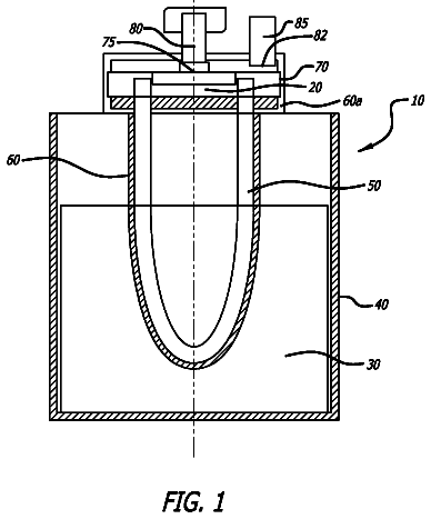
FIG. 1 shows, in the form of a diagram, a working example of a jet mill in a partly cutaway schematic drawing.
FIG. 2 shows a working example of a pneumatic classifier of a jet mill in vertical arrangement and as a schematic middle longitudinal section, the outlet pipe for the mixture of classifying air and solid particles being coordinated with the classifying wheel.
FIG. 2 a shows a working example of a pneumatic classifier analogous to FIG. 2 but with flushing of classifier gap 8 a and shaft lead-through 35 b.
FIG. 3 shows, in schematic representation and as a vertical section, a classifying wheel of a pneumatic classifier.
FIG. 3 a shows, in schematic representation and as a vertical section, a classifying wheel of a pneumatic classifier analogous to FIG. 3 but with flushing of classifier gap 8 a and shaft lead-through 35 b.
FIG. 4 shows a scheme for evaluating the IR spectra.
Detailed description of the invention
On the basis of the conventional art described above, the object of the present invention is to provide precipitated silicas from which the above-mentioned disadvantages of the precipitated silicas have been completely or at least partially eliminated. A further object is to provide a process for preparing the precipitated silicas of the invention.
Further objects, not explicitly stated, will emerge from the overall context of the description, examples and claims.
Surprisingly, this and other objects have been achieved by the present invention the first embodiment of which includes the precipitated silicas that are defined in greater detail in the description below and also in the claims and in the examples.
In a first embodiment, the present invention provides precipitated silicas having an SiOH.sub.isolated absorbance ratio of greater than or equal to 1.5, a silanol group density of 1 to 3.0 SiOH/nm.sup.2 and a modified tapped density of 1 to 50 g/l, and are characterized in that the pH of the precipitated silica is in the range of 3-5.
In further embodiments, the invention provides precipitated silicas, preferably hydrophilic precipitated silicas, which in addition to the stated parameters, independently of one another, have one or more of the following physicochemical parameters:
TABLE-US-00001 BET surface area 50-600 m.sup.2/g CTAB surface area 50-350 m.sup.2/g DBP (anhydrous) 150-400 g/100 g loss on ignition 0.1%-3.0% by weight loss on drying 0.1%-3.0% by weight fraction of particles <1 μm in the 5% to 100% volume-based particle distribution d.sub.90 value of the volume-based 0.001 to 10 μm particle distribution
In another embodiment, the present invention further provides a process for preparing the precipitated silicas of the invention as defined in the claims and the description below.
Additional embodiments provided by the present invention include the use of the precipitated silicas of the invention in sealants, especially in silicone rubber and silicone sealants and with particular preference in RTV-1K sealants. Application is possible in different crosslinking systems, e.g. acetoxy-crosslinking, alkoxy-crosslinking and oxime-crosslinking. These systems are employed, for example, in the building industry as joint-sealants, in the automotive industry as adhesives and sealants, and as coating materials for textile fabric, for example.
Further embodiments provide sealants based on silicone rubber which comprise the precipitated silicas of the invention, and their use.
The precipitated silicas of the invention have the advantage that, on the basis of their special structure and surface qualities, they ensure high storage stability, a firm consistency and an optimum yield point of the silicone rubber when incorporated into silicone rubber compositions, especially those of the RTV-1K type, without the silicone rubber formulations containing a stabilizer.
The inventors have surprisingly found out that precipitated silicas having an SiOH.sub.isolated absorbance ratio of greater than or equal to 1.5, a silanol group density of 1 to 3.0 SiOH/nm.sup.2, and a modified tapped density of 1 to 50 g/l, if they have a pH in the range of 3-5, allow good storage stability on the part of silicone rubber formulations without the addition of a stabilizer.
The precipitated silicas of the invention have the advantage, moreover, that through the specific combination of parameters claimed in Claim 1 , the required amount of crosslinker in RTV-1K silicone rubber formulations can be reduced significantly, leading to a notable economic advantage.
In spite of the absence of a stabilizer and the reduction in the amount of crosslinker, RTV-1K formulations comprising the precipitated silicas of the invention feature a high thixotropy. Furthermore, the precipitated silicas of the invention can be dispersed rapidly and effectively into silicone rubber formulations and hence a high thickening action can be achieved in RTV-1K silicone rubber compositions.
Moreover, the precipitated silicas of the invention, being more inexpensive to prepare, offer a substantial cost advantage over the fumed silicas used to date in RTV1 silicone rubber.
In the present invention the terms silica and precipitated silica are used synonymously. By hydrophilic precipitated silicas are meant those whose surface shows hydrophilic behavior when incorporated by stirring into water, i.e. those whose surface is completely wetted by water and therefore have a contact angle with respect to water of less than 90°. The hydrophilic precipitated silicas of the invention preferably have a carbon content of <0.5% by weight.
The silicas of the invention are distinguished by the fact that they have a particularly high proportion of isolated SiOH groups, as expressed by the SiOH.sub.isolated absorbance ratio, on their surface. The SiOH.sub.isolated absorbance ratio of the silicas of the invention is greater than or equal to 1.5, preferably between 1.5 and 10, more preferably between 1.5 and 7, very preferably between 1.8 and 5, with especial preference between 2 and 4.5, with very special preference between 2.3 and 4.0 and with particular preference between 2.3 and 3.5. This particular surface quality of the precipitated silicas of the invention is an important property, and as a result of this property, silicone rubber formulations containing the precipitated silicas according to the claimed invention, have a high level of storage stability, improved firmness of consistency, and an optimized flow behavior.
Furthermore, the precipitated silicas of the invention are distinguished by a low silanol group density, i.e. a wide spacing of the silanol groups on the precipitated silica surface. For the determination of the silanol group density, the number of silanol groups on the surface of the precipitated silica is first determined by means of LiAlH.sub.4. This alone, however, is not meaningful, since precipitated silicas with a high surface area generally have a higher absolute number of silanol groups than do precipitated silicas with a low surface area. Consequently it is necessary to relate the number of silanol groups to the surface area of the precipitated silica. A suitable measurement of surface area for this purpose is the BET surface area, since this describes the surface area which is available even to relatively small molecules such as water, for example. The silanol group density of the precipitated silicas of the invention is in the range from 1.0 to 3.0 SiOH/nm.sup.2, preferably from 1.0 to 2.8 SiOH/nm, more preferably from 1.5 to 2.8 SiOH/nm.sup.2. If the number of silanol groups per nm.sup.2 is too low, an excessively low yield point may result and may consequently have an adverse effect on the consistency of the silicone sealants.
Moreover, the precipitated silicas of the invention have a low modified tapped density. It should be noted here that the modified tapped density is a reference to the tapped density as measured on the uncompacted material. In order to be able to determine this variable even on materials which have already undergone preliminary compaction as a result of packaging and storage, it is necessary to carry out sample preparation as described in the section “Determining the modified tapped density”. The precipitated silicas of the invention preferably have a modified tapped density of 1 to 50 g/l, more preferably of 5 to 55 g/l, very preferably of 10 to 50 g/l, and with particular preference of 10 to 30 g/l.
The precipitated silicas of the invention are distinguished, finally, by a pH in the range of 3-5, preferably 3.5 to 5, more preferably 4 to 4.7. The low pH of the precipitated silicas of the invention allows omission of a stabilizer when the silicone rubber formulations are formulated, and allows good storage stability to be achieved even without stabilizer.
Without being tied to any specific theory, the special properties of the precipitated silicas of the invention, i.e., the fact that they allow the preparation of storage-stable silicone rubber formulations having outstanding performance properties, such as good consistency and rheology, for example, without addition of stabilizer, may be explained as a result of the high number of isolated SiOH groups of the precipitated silicas in combination with their broad spacing, the low modified tapped density, and, in particular, the low pH. Furthermore, this specific combination of physicochemical properties on the part of the precipitated silicas of the invention means that, when the silicas of the invention are used as a filler in silicone rubber formulations, only small amounts of crosslinker are needed for the formulation.
The specific BET surface area describes the effect of the silica on the incorporation characteristics into silicone rubber and also on the crude mixing properties (cf. S. Brunauer, P. H. Emmett, E. Teller, “Adsorption of Gases in Multimolecular Layers”, J. Am. Chem. Soc. 60, 309 (1938)). Thus the precipitated silicas of the invention may have a BET surface area of 50 to 600 m.sup.2/g, preferably 50 to 400 m.sup.2/g, more preferably 50 to 250 m.sup.2/g, very preferably 80 to 230 m.sup.2/g, especially preferably of 100 to 180 m.sup.2/g, more especially preferably of 125 to 180 m.sup.2/g, and, with more particular preference, of 140 to 170 m.sup.2/g.
The specific CTAB surface area may be of decisive importance primarily for the reinforcing property of the silica (cf. Janzen, Kraus, Rubber Chem. Technol. 44, 1287 (1971)). The reinforcing potential increases with increasing CTAB surface area. Thus the precipitated silicas of the invention may have a CTAB surface area of 50 to 350 m.sup.2/g, more preferably 50 to 250 m.sup.2/g, very preferably of 80 to 230 m.sup.2/g, especially preferably of 100 to 200 m.sup.2/g, and very especially preferably of 125 to 190 m.sup.2/g.
It has additionally been found that a high DBP absorption on the part of the precipitated silicas of the invention may be of benefit in order to obtain effective rheological properties in the silicone rubber formulations. Excessively high DBP values, however, may lead to an excessive increase in the viscosity of the silicone rubber and ought therefore to be avoided. The precipitated silicas of the invention, accordingly, preferably have a DBP absorption of 150 to 400 g/(100 g), more preferably 200 to 350 g/(100 g), very preferably of 220 to 330 g/(100 g), especially preferably of 250 to 330 g/(100 g), and very especially preferably of 260 to 320 g/(100 g).
The inventors have observed, moreover, that for the consistency of the silicone sealants it may be of particular advantage if the precipitated silicas of the invention contain a sufficient fraction of fine particles, i.e. of particles <1 μm. This applies to all of the embodiments described above. Therefore, a fine particle fraction of particles in the particle size range <1 μm of the volume-based particle distribution of the precipitated silicas of the invention may be 30% to 100%, preferably 30% to 95%, more preferably 35% to 95%, very preferably 35% to 90%, especially preferably 40% to 90%, with especial preference 45% to 80%, and, with more particular preference, of 50% to 80%.
It has also been observed that an excessive fraction of coarse particles may adversely affect the performance properties of the precipitated silicas of the invention. For this reason, the precipitated silicas of the invention may preferably be distinguished by a d.sub.90 value, relative to the volume-based particle distribution curve, of between 0.001 and 10 μm, preferably between 1 and 10 μm, more preferably between 2 and 8 μm and with particular preference between 3 and 7 μm.
The particle distributions may be monomodal or bimodal, preferably bimodal.
It has also been observed that for all of the above-described embodiments of the silicas of the invention it may be of particular advantage if from the outset the precipitated silica introduces very little moisture into the silicone sealant. The precipitated silicas of the invention may therefore have an initial moisture content, expressed by the loss on drying, of 0.1% to 3.0%, preferably 0.2% to 2.5%, more preferably 0.3% to 2.0%, and with particular preference 0.4% to 1.8% by weight and/or a loss on ignition of 0.1%-3.0%, preferably 0.2% to 3.0%, more preferably 0.3% to 2.0%, and with particular preference 0.4% to 1.8% by weight.
The stated ranges of preference may be set independently of one another.
The precipitated silicas of the invention may be prepared by a process which comprises:
1) reacting at least one silicate with at least one acidifier;
2) filtering and washing the resulting precipitated silica;
3) drying the resulting precipitated silica or filtercake;
4) optionally grinding the precipitated silica obtained after drying;
5) heat-treating the dried and/or ground precipitated silica; and
6) optionally grinding the precipitated silica obtained after heat treating;
and which is characterized in that after 3) and/or 4) and/or 5) and/or 6) at least one acidifier is added such that the precipitated silica obtained at the end of the process has a pH of 3-5.
The reacting in 1) here preferably comprises:
1a) preparing an initial charge of water or of water and at least one silicate and/or a silicate solution, the pH of the resulting initial charge being preferably between 5 and 10 and the temperature of the initial charge being preferably between 80 and 100° C.; 1b) metering at least one silicate and/or a silicate solution and at least one acidifier into the initial charge from 1a) with stirring at 80 to 100° C. until the solids content of the precipitation suspension reaches a level which leads to the solids content which is to be reached in 1c) (With particular preference, silicate and/or silicate solution and acidifier are added simultaneously and/or in such a way that the pH for the period of 1b) is kept constant at a level between 7 and 10.); 1c) adding an acidifier at a temperature of the precipitation suspension of 80 to 100° C., so that the pH of the precipitation suspension is lowered to 2 to 6 and the final solids content of the precipitation suspension is between 30 and 70 g/l.
Preferably the precipitated silicas of the invention are ground. This takes place with particular preference by grinding the precipitated silicas of the invention in 4), i.e. between 3) and 5), or in 6), i.e. after 5), or both in 4), i.e. between 3) and 5), and in 6), i.e. after 5).
All known forms of silicate are suitable for the silicates or silicate solutions used in step 1) of the process of the invention. The silicates used in accordance with the invention may preferably be alkaline silicates, e.g. sodium or potassium silicates. With particular preference the silicate in step 1 may be sodium silicate (waterglass). Its weight ratio of SiO.sub.2 to Na.sub.2O may be between 2 and 4, preferably between 3 and 3.6 and more preferably between 3.3 and 3.5. The SiO.sub.2 content may be between 20% and 40% by weight, preferably between 25% and 35% by weight and more preferably between 25% and 30% by weight.
Acidifiers are acidic compounds of organic or inorganic type which can be used to lower the pH of the precipitation suspension. With preference it may be possible to use inorganic acids such as hydrochloric acid, phosphoric acid, sulfuric acid or nitric acid, or organic acids such as acetic acid, formic acid or carbonic acid or carbon dioxide. Both dilute and concentrated acids may be used. With particular preference the process of the invention uses sulfuric acid.
In the majority of cases the silicate and/or the silicate solution and acidifier used in 1a) to 1c) may be identical.
The pH of the initial charge in 1a) may preferably be between 7 and 10, more preferably between 8 and 9. The temperature of the initial charge may be set at 80 to 100° C., preferably at 85 to 95° C.,
In 1b) silicate and acidifier may be preferably metered in simultaneously. The addition of the two components preferably takes place continuously and constantly over the entire period of 1b). During this period the temperature remains at 80 to 100° C., preferably at 85 to 95° C. The period of the addition lasts until the solids content to be achieved at the end of 1c) has been achieved. It may in this case be necessary to continue the precipitation beyond the viscosity rise point. This viscosity rise point corresponds to the point in time at which a sharp rise is observed in the viscosity of the precipitation suspension in the course of precipitation; cf. EP 0643015. During 1b), in which the precipitation of the silica begins, the pH may be as far as possible kept constantly at a level of between 7 and 10, preferably constant at a level of between 7.5 and 9.5 and with very particular preference at a pH of between 8 and 9. Corrections to an off-target pH may be generally made by increasing or lowering the addition of the acidifier, so that the set pH preferably fluctuates only by ±0.2 pH units, more preferably by only ±0.1 pH units.
Through addition of an acidifier at a temperature of the precipitation suspension of 80 to 100° C. its pH is lowered in 1c) to 2 to 6, preferably 3 to 6, more preferably to 3 to 4. The solids content of the precipitation suspension at the end of this substep may be between 30 and 70 g/l, preferably between 45 and 60 g/l and with very particular preference between 45 and 55 g/l.
Without in any way being tied to one particular theory, the intention is that, by suitable choice of the process parameters, a chain-like structure of the aggregates should be constructed in 1b). A reinforcement of this hitherto quite loose aggregate structure may be attained by the correspondingly slow further precipitation even after the viscosity rise point.
The metering rates in 1b) may be selected in all embodiments of the process of the invention, both before and after the viscosity rise point, such that the solids content which is to be achieved after acidification in 1c), of 30 to 70 g/l, may be reached.
The filtration, liquefaction (e.g. in accordance with DE 2447613) and extended or accelerated drying of the precipitated silicas of the invention are familiar to the person skilled in the art and can be looked up, for example, in the documents cited in the description. The filtration and the washing of the precipitated silica take place preferably in such a way that the conductivity of the end product is <1000 μS/cm, preferably <500 μS/cm and more preferably <200 μS/cm.
The precipitated silica of the invention may be dried preferably in a pneumatic conveying drier, spray drier, rack drier, belt drier, rotary tube drier, flash drier, spin-flash drier or nozzle tower drier. These drying variants include operation with an atomizer, with a single-fluid or two-fluid nozzle or with an integrated fluid bed. Spray drying may be carried out in accordance for example with U.S. Pat. No. 4,094,771.
If the selected mode of drying is spray drying, which may be particularly preferred, then the filtercake should be redispersed beforehand. Redispersion may take place preferably in water or aqueous acid so that the dispersion has a pH of 4 to 7. It should be ensured here that the silica dispersion when redispersion is at an end has a solids content of 5% to 18%, preferably 8% to 13% by weight, more preferably 9% to 11%, and that in the course of redispersion the shearing forces acting on the precipitated silica are not too great. This can be achieved, for example, by stirring with a rotary speed of <1000 rpm, with preferably generalized rather than localized stirring. The redispersed precipitated silica dispersion may be metered into the spray drier preferably such that the temperature at the drier exit is from 100 to 170° C., preferably 120 to 160° C., and more preferably 130-160° C.
The grinding of the precipitated silicas of the invention may take place for example as described in Ullmann, 5th edition, B2, 5-20. Preferably the grinding of the precipitated silicas of the invention takes place in 4) and/or in 6), very preferably in 4). For this purpose it may be preferred in particular to use a grinding system (grinding apparatus) comprising or consisting of impact mills or jet mills, preferably opposed-jet mills. Particular preference may be given to using fluid-bed opposed-jet mills. With very particular preference, grinding takes place by means of a grinding system (grinding apparatus), with particular preference a grinding system comprising a jet mill, characterized in that the mill of the grinding system may be operated in the grinding phase with an operational medium selected from the group consisting of gas and/or vapor, preferably steam, and/or a gas comprising steam, and in that the grinding chamber may be heated in a heating phase, i.e. before the actual operation with the operational medium, such that the temperature in the grinding chamber and/or at the mill outlet is higher than the dew point of the vapor and/or operational medium.
Grinding takes place with particular preference in accordance with the method described in DE 10 2006 048 850.4, using the grinding system (mill) described therein, the operational medium used being, with especial preference, steam. In order to avoid pure repetitions of text, the content of the cited patent is hereby explicitly incorporated by reference in its entirety as part of the content of the present specification. The grinding parameters are preferably chosen such that the ground product may have a fine-particle fraction, in the region smaller than 1 μm of the volume-based particle distribution, of 5% to 100%, preferably 10% to 95%, more preferably 15% to 95%, with very particular preference 20% to 90%, and with particular preference, of 40% to 80%, and/or a d.sub.90 value in the volume-based particle distribution curve of between 0.001 and 10 μm.
In one especially preferred embodiment, in preparation for actual grinding with superheated steam, a fluid-bed opposed-jet mill as shown in FIG. 1 , with an integrated dynamic pneumatic classifier as shown in FIGS. 2 and 2 a , is first heated via the two heating nozzles ( 5 a ) (of which only one is depicted in FIG. 1 ) which are charged with hot compressed air, preferably at 10 bar and 160° C., until the mill exit temperature is higher than the dew point of the vapor and/or operational medium, preferably about 105° C.
Connected downstream of the mill, for the separation of the ground material, is a filter system (not shown in FIG. 1 ) whose filter housing is heated in its lower third indirectly, via attached heating coils, by means of saturated steam (preferably 6 bar saturated steam), likewise for the purpose of preventing condensation. All of the apparatus surfaces in the region of the mill, the separation filter, and the supply lines for steam and hot compressed air have special insulation.
After the desired heating temperature has been reached, the supply of hot compressed air to the heating nozzles is shut off and the charging of the three grinding nozzles with superheated steam, preferably at 38 bar (abs) and 325° C., is commenced.
In order to protect the filter medium used in the separation filter and also in order to set a defined level of residual water in the ground material, of preferably 2% to 6%, water is introduced in the starting phase, and during grinding, into the grinding chamber of the mill, via a two-fluid nozzle operated with compressed air, as a function of the mill exit temperature.
The feed quantity is regulated as a function of the classifier flow which comes about. The classifier flow regulates the feed quantity such that it is not possible to exceed approximately 70% of the nominal flow.
The introduction member ( 4 ) which functions here is a speed-regulated bucket wheel which meters the feed material from a reservoir container via a cyclical lock, which serves as a barometric endpoint, into the grinding chamber, which is at superatmospheric pressure.
The coarse material is comminuted in the expanding steam jets (grinding gas). Together with the depressurized grinding gas, the product particles ascend in the center of the mill vessel to the classifying wheel. Depending on the classifier speed and grinding steam quantity which have been set, the particles whose fineness is sufficient enter along with the grinding steam into the fines exit, and from there they pass into the downstream separating system, while particles which are too coarse pass back into the grinding zone and are subjected to a repeat comminution. The discharge of the separated fines from the separation filter into the subsequent silo storage and bagging operation takes place by means of a bucket-wheel lock.
The grinding pressure of the grinding gas that obtains at the grinding nozzles, and the resulting volume of grinding gas, in conjunction with the speed of the dynamic paddle wheel classifier, determine the fineness of the particle-size distribution function and also the upper particle-size limit.
In one preferred embodiment, the process according to the invention may be carried out in a grinding system (grinding apparatus), preferably in a grinding system comprising a jet mill, particularly preferably comprising an opposed-jet mill. For this purpose, a feed material to be comminuted is accelerated in expanding gas jets of high velocity and comminuted by particle-particle impacts. Very particularly preferably used jet mills are fluid-bed opposed-jet mills or dense-bed jet mills or spiral jet mills. In the case of the very particularly preferred fluid-bed opposed-jet mill, two or more grinding jet inlets are located in the lower third of the grinding chamber, preferably in the form of grinding nozzles, which are preferably present in a horizontal plane. The grinding jet inlets are particularly preferably arranged at the circumference of the preferably round mill vessel so that the grinding jets all meet at one point in the interior of the grinding container. Particularly preferably, the grinding jet inlets are distributed uniformly over the circumference of the grinding container. In the case of three grinding jet inlets, the spacing would therefore be 120° in each case.
In a special embodiment of the process according to the invention, the grinding system (grinding apparatus) comprises a classifier, preferably a dynamic classifier, particularly preferably a dynamic paddle wheel classifier, especially preferably a classifier according to FIGS. 2 and 3 .
In a particularly preferred embodiment, a dynamic pneumatic classifier according to FIGS. 2 a and 3 a may be used. This dynamic pneumatic classifier contains a classifying wheel and a classifying wheel shaft and a classifier housing, a classifier gap being formed between the classifying wheel and the classifier housing and a shaft lead-through being formed between the classifying wheel shaft and the classifier housing, and is characterized in that flushing of classifier gap and/or shaft lead-through with compressed gases of low energy may be effected. By using a classifier in combination with the jet mill operated under the conditions according to the invention, a limit is imposed on the oversize particles, the product particles ascending together with the depressurized gas jets being passed from the center of the grinding container through the classifier, and the product which has a sufficient fineness then being discharged from the classifier and from the mill. Particles which are too coarse return to the grinding zone and are subjected to further comminution.
In the grinding system, a classifier can be connected as a separate unit downstream of the mill, but an integrated classifier is preferably used. One particularly preferred grinding operation includes a heating phase upstream of the actual grinding step, in which phase it is ensured that the grinding chamber, particularly preferably all substantial components of the mill and/or of the grinding system on which water and/or steam could condense, is/are heated up so that its/their temperature is above the dew point of the vapor. Heating up can in principle be effected by any heating method. However, the heating up is preferably effected by passing hot gas through the mill and/or the entire grinding system so that the temperature of the gas is higher at the mill exit than the dew point of the vapor. Particularly preferably here it is ensured that the hot gas preferably sufficiently heats up all substantial components of the mill and/or of the entire grinding system which come into contact with the steam.
The heating gas used may in principle be any desired gas and/or gas mixtures, but hot air and/or combustion gases and/or inert gases are preferably used. The temperature of the hot gas is above the dew point of the steam. The hot gas may in principle be introduced at any desired point into the grinding chamber. Inlets or nozzles are preferably present for this purpose in the grinding chamber. These inlets or nozzles may be the same inlets or nozzles through which the grinding jets are also passed during the grinding phase (grinding nozzles). However, it is also possible for separate inlets or nozzles (heating nozzles) through which the hot gas and/or gas mixture can be passed to be present in the grinding chamber. In a preferred embodiment, the heating gas or heating gas mixture is introduced through at least two, preferably three or more, inlets and nozzles which are arranged in a plane and are arranged at the circumference of the preferably round mill container in such a way that the jets all meet at one point in the interior of the grinding container. Particularly preferably, the inlets or nozzles are distributed uniformly over the circumference of the grinding container.
During the grinding, a gas and/or a vapor, preferably steam and/or a gas/steam mixture, may be let down through the grinding jet inlets, preferably in the form of grinding nozzles, as operating medium. This operating medium has as a rule a substantially higher sound velocity than air (343 m/s), preferably at least 450 m/s. Advantageously, the operating medium comprises steam and/or hydrogen gas and/or argon and/or helium. It may particularly preferably be superheated steam. In order to achieve very fine grinding, it has proved particularly advantageous if the operating medium is let down into the mill at a pressure of 15 to 250 bar, particularly preferably of 20 to 150 bar, very particularly preferably 30 to 70 bar and especially preferably 40 to 65 bar. The operating medium also particularly preferably has a temperature of 200 to 800° C., particularly preferably 250 to 600° C. and in particular 300 to 400° C.
In the case of steam as an operating medium, i.e. particularly when the vapor feed pipe is connected to a steam source, it proves to be particularly advantageous if the grinding or inlet nozzles are connected to a vapor feed pipe which is equipped with expansion bends.
Furthermore, it has proved to be advantageous if the surface area of the jet mill has as small a value as possible and/or the flow paths are at least substantially free of projections and/or if the components of the jet mill are designed for avoiding accumulations. By these measures, deposition of the material to be ground in the mill may additionally be prevented.
The invention may be explained in more detail merely by way of example with reference to the below-described preferred and special embodiments of the process according to the invention and the preferred and particularly suitable versions of jet mills and the drawings and descriptions of the drawings. These working and use examples are provided herein for purposes of illustration only, and are not intended to be limiting unless otherwise specified.
Individual features which are stated and/or shown in relation to specific working examples are not limited to these working examples or the combination with the other features of these working examples but may be combined, within the technical possibilities, with any other variants, even if they are not separately discussed in the present documents.
Identical reference numerals in the individual figures and images of the drawings designate identical or similar components or components having an identical or similar effect. The diagrams in the drawing also clarify those features which are not provided with reference numerals, regardless of whether such features are described below or not. On the other hand, features which are contained in the present description but not visible or shown in the drawing, are also readily understandable for a person skilled in the art.
As already indicated above, a jet mill, preferably an opposed-jet mill, comprising integrated classifier, preferably an integrated dynamic pneumatic classifier, may be used for the production of very fine particles in the process according to the invention. Particularly preferably, the pneumatic classifier contains a classifying wheel and a classifying wheel shaft and a classifier housing, a classifier gap being formed between the classifying wheel and the classifier housing and a shaft lead-through being formed between the classifying wheel shaft and the classifier housing, and is operated in such a way that flushing of classifier gap and/or shaft lead-through with compressed gases of low energy is effected.
Preferably, the flushing gas may be used at a pressure of not more than at least approximately 0.4 bar, particularly preferably not more than at least about 0.3 bar and in particular not more than about 0.2 bar above the internal pressure of the mill. The internal pressure of the mill may be at least approximately in the range from 0.1 to 0.5 bar.
Furthermore, it may be preferable if the flushing gas is used at a temperature of about 80 to about 120° C., in particular approximately 100° C., and/or if the flushing gas used is low-energy compressed air, in particular at about 0.3 bar to about 0.4 bar.
The speed of a classifying rotor of the pneumatic classifier and the internal amplification ratio V (=Di/DF) may be chosen or set or may be regulated so that the circumferential speed of the operating medium (B) at an immersed pipe or exit port coordinated with the classifying wheel reaches up to 0.8 times the sound velocity of the operating medium. In the formula V (=Di/DF), Di denotes the internal diameter of the classifying wheel ( 8 ), i.e. the distance between the inner edges of the blades ( 34 ), and DF denotes the internal diameter of the immersed pipe ( 20 ). In one particularly preferred embodiment the internal diameter of the classifying wheel, Di, may be 280 mm and the internal diameter of the immersed pipe, DF, may be 100 mm. For the definition of the amplification ratio, see also Dr. R. Nied, “Strömungsmechanik und Thermodynamik in der mechanischen Verfahrenstechnik”, available from the Corporate Consultancy of Dr. Roland Nied, 86486 Bonstetten, Germany. Also available from NETZSCH-CONDUX Mahltechnik GmbH, Rodenbacher Chaussee 1, 63457 Hanau, Germany.
The description continues in the full USPTO document.
 Lapsed, fee not paid3 drawings