 Lapsed, fee not paid10 drawings
Vehicles & Drones · US 9,738,337 B2
Climbing robot vehicle
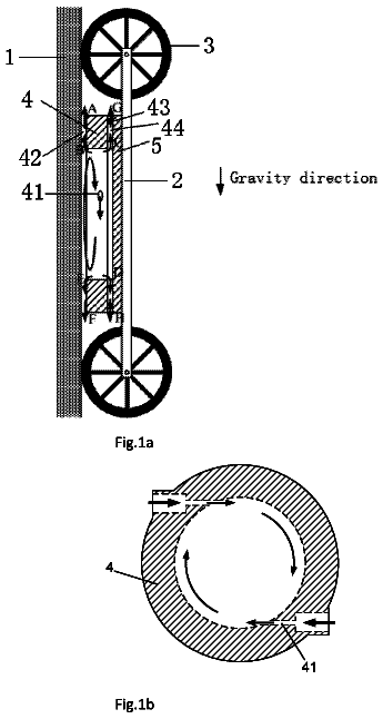
A climbing robot vehicle comprises a vehicle ( 2 ) and the front and rear ends of the vehicle body are provided with wheels ( 3 ).
US 9,738,346 B2 · Assignee: SHOWA CORPORATION · Inventors: Kasuga; Takahiro et al.
Sheet 1 of 15 from the published document. All sheets in the USPTO PDF
A vehicle height adjustment device includes a changer and a controller. The changer is configured to change a relative position of a body of a vehicle relative to an axle of a wheel of the vehicle. The controller is configured to control the changer to make the relative position a target value so as to control a vehicle height of the body. The controller is configured to control the changer to maintain the relative position when there is a possibility of a malfunction in a detector configured to detect a parameter for control.
Field The present invention relates to a vehicle height adjustment device. Related Art Japanese Examined Patent Publication No. 8-22680 discloses a vehicle height adjustment device that increases the height of a motorcycle during travel and that decreases the height of the motorcycle during halt in order to facilitate a rider's or a passenger's getting on and off the motorcycle.
1 of 15 drawing sheets so far from the published document, cropped to the drawing. Every sheet is in the USPTO PDF.
What the patent claimed, word for word. All of it is now free to use.
The present application claims priority from Japanese Patent Application No. 2015-065985, filed Mar. 27, 2015, the entire contents of which are incorporated herein by reference.
Field
The present invention relates to a vehicle height adjustment device.
Related Art
Japanese Examined Patent Publication No. 8-22680 discloses a vehicle height adjustment device that increases the height of a motorcycle during travel and that decreases the height of the motorcycle during halt in order to facilitate a rider's or a passenger's getting on and off the motorcycle.
According to one aspect of the present disclosure, a vehicle height adjustment device includes a changer and a controller. The changer is configured to change a relative position of a body of a vehicle relative to an axle of a wheel of the vehicle. The controller is configured to control the changer to make the relative position a target value so as to control a vehicle height of the body. The controller is configured to control the changer to maintain the relative position when there is a possibility of a malfunction in a detector configured to detect a parameter for control.
A more complete appreciation of the present invention and many of the attendant advantages thereof will be readily obtained as the same becomes better understood by reference to the following detailed description when considered in connection with the accompanying drawings, wherein:
FIG. 1 illustrates a schematic configuration of a motorcycle according to an embodiment;
FIG. 2 is a cross-sectional view of a front fork according to the embodiment;
FIG. 3 is an enlarged view of part III illustrated in FIG. 2 ;
FIG. 4 is an enlarged view of part IV illustrated in FIG. 3 ;
FIG. 5 illustrates how the front fork operates at the time of a compression stroke;
FIG. 6 illustrates how the front fork operates at the time of a rebound stroke;
FIG. 7 illustrates a flow of oil in a front-wheel passage switch unit in a first switch state;
FIG. 8 illustrates a flow of oil in the front-wheel passage switch unit in a second switch state;
FIG. 9 illustrates a flow of oil in the front-wheel passage switch unit in a third switch state;
FIG. 10 illustrates a flow of oil in the front-wheel passage switch unit in a fourth switch state;
FIG. 11A illustrates whether a first communication passage, a second communication passage, and a third communication passage are open or closed when the front-wheel passage switch unit is in the first switch state;
FIG. 11B illustrates whether the first communication passage, the second communication passage, and the third communication passage are open or closed when the front-wheel passage switch unit is in the second switch state;
FIG. 11C illustrates whether the first communication passage, the second communication passage, and the third communication passage are open or closed when the front-wheel passage switch unit is in the third switch state;
FIG. 12 is a block diagram of a controller;
FIG. 13 is a block diagram of a passage switch unit controller;
FIG. 14A is a time chart illustrating an exemplary occurrence that is due to a malfunction of a front-wheel current detector;
FIG. 14B is a time chart illustrating control details of a malfunction detector according to the embodiment; and
FIG. 15 is a flowchart of a procedure for control processing performed by the malfunction detector.
The embodiments will now be described with reference to the accompanying drawings, wherein like reference numerals designate corresponding or identical elements throughout the various drawings.
FIG. 1 illustrates a schematic configuration of a motorcycle 1 according to this embodiment.
The motorcycle 1 includes a front wheel 2 , a rear wheel 3 , and a body 10 . The front wheel 2 is a wheel on the front side of the motorcycle 1 . The rear wheel 3 is a wheel on the rear side of the motorcycle 1 . The body 10 includes elements such as a frame 11 , a handle 12 , an engine 13 , and a seat 19 . The frame 11 defines the framework of the motorcycle 1 .
The motorcycle 1 includes two front forks 21 . One of the front forks 21 is on the right side of the front wheel 2 , and the other one of the front forks 21 is on the left side of the front wheel 2 . The front forks 21 are examples of a suspension device that couples the front wheel 2 and the body 10 to each other. The motorcycle 1 includes two rear suspensions 22 . One of the rear suspensions 22 is on the right side of the rear wheel 3 , and the other one of the rear suspensions 22 is on the left side of the rear wheel 3 . The rear suspensions 22 couple the rear wheel 3 and the body 10 to each other. FIG. 1 illustrates only the front fork 21 and the rear suspension 22 that are on the right side of the motorcycle 1 . The front fork 21 and the rear suspension 22 are an example of the changer to change the position of the body 10 relative to the axle of the front wheel 2 and the position of the body 10 relative to the axle of the rear wheel 3 .
The motorcycle 1 includes two brackets 14 and a shaft 15 . The shaft 15 is disposed between the two brackets 14 . The two brackets 14 respectively hold the front fork 21 on the right side of the front wheel 2 and the front fork 21 on the left side of the front wheel 2 . The shaft 15 is rotatably supported by the frame 11 .
The motorcycle 1 includes a controller 70 . The controller 70 controls the height of the motorcycle 1 by controlling a front-wheel passage switch unit 300 , described later, of each front fork 21 and a rear-wheel passage switch unit 302 , described later, of each rear suspension 22 . The front-wheel passage switch unit 300 and the rear-wheel passage switch unit 302 are non-limiting examples of an actuator.
The motorcycle 1 also includes a front-wheel rotation detection sensor 31 and a rear-wheel rotation detection sensor 32 . The front-wheel rotation detection sensor 31 detects the rotation angle of the front wheel 2 . The rear-wheel rotation detection sensor 32 detects the rotation angle of the rear wheel 3 .
Configuration of Front Fork 21
Each front fork 21 will be described in detail below.
FIG. 2 is a cross-sectional view of the front fork 21 according to this embodiment.
The front fork 21 according to this embodiment is what is called an upright front fork that is disposed between the body 10 and the front wheel 2 of the motorcycle 1 so as to support the front wheel 2 . The upright front fork 21 includes an outer member 110 (detailed later) and an inner tube 210 (detailed later). The outer member 110 is disposed on the side of the front wheel 2 , and the inner tube 210 is disposed on the side of the body 10 .
The front fork 21 includes an axle side unit 100 and a body side unit 200 . The axle side unit 100 includes the outer member 110 and is mounted on the axle of the front wheel 2 . The body side unit 200 includes the inner tube 210 and is mounted on the body 10 . The front fork 21 also includes a front-wheel spring 500 . The front-wheel spring 500 is disposed between the axle side unit 100 and the body side unit 200 to absorb vibrations transmitted to the front wheel 2 caused by the roughness of a ground surface.
The outer member 110 and the inner tube 210 are coaxial, hollow cylindrical members. A direction of the center line (that is, an axial direction) of each cylinder will be hereinafter occasionally referred to as “vertical direction”. In this case, the body 10 side will occasionally be referred to the upper side, and the front wheel 2 side will occasionally be referred to as the lower side. By moving the axle side unit 100 and the body side unit 200 relative to each other in the vertical direction (axial direction), the front fork 21 absorbs vibrations caused by the roughness of the ground surface while supporting the front wheel 2 .
Configuration of Axle Side Unit 100
The axle side unit 100 includes the outer member 110 , an attenuation force generation unit 130 , a rod 150 , and a rod holding member 160 . The outer member 110 is mounted on the axle of the front wheel 2 . The attenuation force generation unit 130 generates attenuation force utilizing viscous resistance of oil. The rod 150 holds the attenuation force generation unit 130 . The rod holding member 160 holds the lower-side end of the rod 150 .
The axle side unit 100 also includes a ball 166 and a regulation member 167 . The ball 166 has a spherical shape and is disposed in an axial depression 161 a , described later, of the rod holding member 160 . The regulation member 167 regulates the movement of the ball 166 .
The axle side unit 100 also includes a spring support member 170 , a support-member holding member 180 , and a guide member 190 . The spring support member 170 supports the lower-side end of the front-wheel spring 500 . The support-member holding member 180 holds the spring support member 170 . The guide member 190 guides the inner tube 210 to move in the axial direction.
Configuration of Outer Member 110
The outer member 110 includes a hollow cylindrical portion 111 and an axle bracket 112 . The hollow cylindrical portion 111 has a hollow cylindrical shape for the inner tube 210 to be inserted into the hollow cylindrical shape. The axle bracket 112 is mountable to the axle of the front wheel 2 .
The hollow cylindrical portion 111 , at its upper end, includes an oil seal 113 and a slide bush 114 . The oil seal 113 seals the gap between the outer surface of the inner tube 210 and the hollow cylindrical portion 111 . The slide bush 114 smoothens the sliding contact between the hollow cylindrical portion 111 and the outer surface of the inner tube 210 .
The axle bracket 112 has an axial through hole 112 a and an axle mounting hole 112 b . The axial through hole 112 a is oriented in the axial direction for the rod holding member 160 to be inserted through the axial through hole 112 a . The axle mounting hole 112 b penetrates the axle bracket 112 in a direction crossing the axial direction to receive the axle of the front wheel 2 .
Configuration of Attenuation Force Generation Unit 130
The attenuation force generation unit 130 includes a piston 131 , an upper-end side valve 136 , and a lower-end side valve 137 . The piston 131 defines an operating oil chamber 50 , which is formed in the space inside a cylinder 230 , described later. The upper-end side valve 136 is disposed at the upper-side end of the piston 131 . The lower-end side valve 137 is disposed at the lower-side end of the piston 131 . The attenuation force generation unit 130 also includes a piston bolt 140 and a nut 145 . The piston bolt 140 supports the piston 131 , the upper-end side valve 136 , the lower-end side valve 137 , and other members. The nut 145 is screwed on the piston bolt 140 to determine the positions of the piston 131 , the upper-end side valve 136 , the lower-end side valve 137 , and other members.
The piston 131 is a hollow cylindrical member and has on its outer surface a hermetic member sealing the gap between the cylinder 230 and the piston 131 . The piston 131 also has a first through hole 132 and a second through hole 133 , which are through holes open in the axial direction. The piston 131 includes first radial conduits 134 and second radial conduits 135 . The first radial conduits 134 radially extend at the upper-side end of the piston 131 and communicate with the first through hole 132 . The second radial conduits 135 radially extend at the lower-side end of the piston 131 and communicate with the second through hole 133 . A non-limiting example of the number of each of the first through holes 132 and the second through holes 133 is three. The three first through holes 132 and the three second through holes 133 are each disposed at equal intervals in a circumferential direction and at positions respectively corresponding to the first through hole 132 and the second through hole 133 .
The upper-end side valve 136 is made up of a stack of approximately disk-shaped metal plates. A through hole penetrates the center of the stack of metal plates. A shaft 141 , described later, of the piston bolt 140 is inserted through the through hole. The upper-end side valve 136 blocks the second through hole 133 and opens the first through hole 132 .
The lower-end side valve 137 is made up of a stack of approximately disk-shaped metal plates. A through hole penetrates the center of the stack of metal plates. The shaft 141 , described later, of the piston bolt 140 is inserted through the through hole. The lower-end side valve 137 blocks the first through hole 132 and opens the second through hole 133 .
The piston bolt 140 includes the shaft 141 and a base 142 . The shaft 141 is disposed on the upper end side of the piston bolt 140 and has a solid cylindrical shape. The base 142 is disposed on the lower end side of the piston bolt 140 and has a solid cylindrical shape of larger radius than the radius of the shaft 141 . In the piston bolt 140 , a depression 143 is formed over the depth from the lower-side end surface of the base 142 to the shaft 141 .
The shaft 141 has a male thread formed at the upper-side end of the shaft 141 . The male thread is screwed on a female thread formed on the nut 145 .
The depression 143 has a female thread formed on the inner surface at the lower-side end of the depression 143 . The female thread receives a male thread formed on the upper-side end of the rod 150 . At the upper-side end of the depression 143 , a radial through hole 144 is formed. The radial through hole 144 radially penetrates the depression 143 to allow the depression 143 to communicate with the outside of the shaft 141 .
On the upper-side end of the nut 145 , a female thread 146 is formed. The female thread 146 receives a male thread of the piston bolt 140 . Under the female thread 146 , a depression 147 is formed. The depression 147 is depressed over a depth from the lower-side end surface of the nut 145 , and has a solid cylindrical shape of larger radius than the radius of the root of the female thread 146 . In the nut 145 , a radial through hole 148 is formed. The radial through hole 148 radially penetrates the nut 145 to allow the outside of the nut 145 to communicate with the depression 147 .
With the configuration described hereinbefore, the attenuation force generation unit 130 is held on the rod 150 with the male thread on the upper-side end of the rod 150 screwed on the female thread on the depression 143 of the piston bolt 140 . The piston 131 is in contact with the inner surface of the cylinder 230 through the hermetic member on the outer surface of the piston 131 . Thus, the piston 131 defines a first oil chamber 51 and a second oil chamber 52 in the space inside the cylinder 230 . The first oil chamber 51 is upper than the piston 131 , and the second oil chamber 52 is lower than the piston 131 .
Configuration of Rod 150
The rod 150 is a hollow cylindrical member, and has male threads at the upper-side end and the lower-side end on the outer surface of the rod 150 . The male thread on the upper-side end of the rod 150 is screwed on the piston bolt 140 of the attenuation force generation unit 130 . The male thread on the lower-side end of the rod 150 is screwed on a female thread 161 d . The female thread 161 d is formed on an upper-end-side solid cylindrical portion 161 . The upper-end-side solid cylindrical portion 161 is disposed on the upper end side of the rod holding member 160 . A lock nut 155 is screwed on the male thread on the lower-side end of the rod 150 . Thus, the rod 150 is secured on the rod holding member 160 .
The rod 150 also has a female thread formed on the inner surface of the rod 150 at the lower-side end of the rod 150 .
Configuration of Rod Holding Member 160
The rod holding member 160 has a plurality of solid cylindrical portions of different diameters. Namely, the rod holding member 160 includes the upper-end-side solid cylindrical portion 161 , a lower-end-side solid cylindrical portion 162 , and an intermediate solid cylindrical portion 163 . The upper-end-side solid cylindrical portion 161 is disposed at the upper-side end of the rod holding member 160 . The lower-end-side solid cylindrical portion 162 is disposed at the lower-side end of the rod holding member 160 . The intermediate solid cylindrical portion 163 is disposed between the upper-end-side solid cylindrical portion 161 and the lower-end-side solid cylindrical portion 162 .
The upper-end-side solid cylindrical portion 161 has the axial depression 161 a , a radial depression 161 b , and a radial through hole 161 c . The axial depression 161 a is depressed over a depth in the axial direction from the upper-side end surface of the upper-end-side solid cylindrical portion 161 . The radial depression 161 b is depressed radially throughout the circumference of the upper-end-side solid cylindrical portion 161 over a depth from the outer surface of the upper-end-side solid cylindrical portion 161 . The radial through hole 161 c penetrates the axial depression 161 a and the radial depression 161 b in a radial direction.
The axial depression 161 a has the female thread 161 d , which receives the male thread on the lower-side end of the rod 150 . The axial depression 161 a also has an inclined surface 161 e . The inclined surface 161 e is inclined relative to the axial direction, that is, the inner diameter of the inclined surface 161 e gradually decreases in the lower side direction.
On the lower-side end of the upper-end-side solid cylindrical portion 161 , a male thread 161 f is formed. The male thread 161 f is screwed on a female thread 181 , which is described later and formed on the support-member holding member 180 .
The intermediate solid cylindrical portion 163 has a diameter smaller than the inner diameter of the axial through hole 112 a of the outer member 110 . Thus, the intermediate solid cylindrical portion 163 is fitted in the axial through hole 112 a of the outer member 110 .
On the outer surface of the lower-end-side solid cylindrical portion 162 , a male thread 162 a is formed.
The rod holding member 160 is secured on the outer member 110 with the male thread 162 a , which is on the lower-end-side solid cylindrical portion 162 , screwed on a nut 165 . The nut 165 is inserted through the axial through hole 112 a of the outer member 110 .
Configuration of Regulation Member 167
The regulation member 167 is a stepped, hollow cylindrical member. The regulation member 167 has a male thread formed on the outer surface at the upper-side end of the regulation member 167 . The regulation member 167 is secured on the rod 150 with the male thread screwed on the female thread on the inner surface at the lower-side end of the rod 150 . The regulation member 167 , at its lower-side end, regulates the movement of the ball 166 , which is disposed in the axial depression 161 a of the rod holding member 160 .
Configuration of Spring Support Member 170
The spring support member 170 is a hollow cylindrical member, and is secured on the upper-side end of the support-member holding member 180 . Examples of the method of securing the spring support member 170 include, but are not limited to, welding and press fitting.
Configuration of Support-Member Holding Member 180
The support-member holding member 180 is a hollow cylindrical member. At the lower-side end of the support-member holding member 180 , the female thread 181 is formed. The female thread 181 receives the male thread 161 f , which is formed on the rod holding member 160 . The support-member holding member 180 is secured on the rod holding member 160 with the female thread 181 receiving the male thread 161 f , which is formed on the rod holding member 160 . The support-member holding member 180 has a communication hole 182 . The communication hole 182 is formed at a position axially corresponding to the radial depression 161 b of the rod holding member 160 , and thus communicates the inside and outside of the support-member holding member 180 with each other.
Configuration of Guide Member 190
The guide member 190 includes a hollow cylindrical portion 191 and an internally facing portion 192 . The hollow cylindrical portion 191 has a hollow cylindrical shape. The internally facing portion 192 radially internally extends from the lower-side end of the hollow cylindrical portion 191 .
The guide member 190 is secured between the rod holding member 160 and the outer member 110 with the internally facing portion 192 held between the rod holding member 160 and the outer member 110 .
The internally facing portion 192 is chamfered at the lower-side end of the internally facing portion 192 . An O ring 195 is fitted in the space defined between the chamfered portion and the rod holding member 160 . The O ring 195 seals the gap between the guide member 190 , the rod holding member 160 , and the outer member 110 . Thus, the O ring 195 keeps the space inside the hollow cylindrical portion 111 of the outer member 110 liquid tight.
In the axle side unit 100 with the configuration described hereinbefore, a reservoir chamber 40 (storage chamber) is defined between the inner surface of the outer member 110 and the outer surfaces of the rod 150 and the support-member holding member 180 . The reservoir chamber 40 stores oil kept hermetic in the front fork 21 .
Configuration of Body Side Unit 200
The body side unit 200 includes the inner tube 210 and a cap 220 . The inner tube 210 has a hollow cylindrical shape with open ends. The cap 220 is mounted on the upper-side end of the inner tube 210 .
The body side unit 200 also includes the cylinder 230 and a hermetic member 240 . The cylinder 230 has a hollow cylindrical shape. The hermetic member 240 is mounted on the lower-side end of the cylinder 230 , and keeps the space inside the cylinder 230 hermetic.
The body side unit 200 also includes a front-wheel spring length adjustment unit 250 and the front-wheel passage switch unit 300 . The front-wheel spring length adjustment unit 250 is a non-limiting example of the adjustor that supports the front-wheel spring 500 at its upper-side end and adjusts (changes) the length of the front-wheel spring 500 . The front-wheel passage switch unit 300 is mounted on the upper-side end of the cylinder 230 and selects a passage for oil, which is a non-limiting example of the fluid.
The body side unit 200 also includes a front-wheel relative position detector 281 (see FIGS. 11A to 11C ). The front-wheel relative position detector 281 detects the position of an upper-side end support member 270 relative to a base member 260 , described later, of the front-wheel spring length adjustment unit 250 .
Configuration of Inner Tube 210
The inner tube 210 is a hollow cylindrical member.
The inner tube 210 , at its lower-side end, includes a slide bush 211 and a movement regulation member 212 . The slide bush 211 has a hollow cylindrical shape and smoothens the sliding contact between the inner tube 210 and the inner surface of the hollow cylindrical portion 111 of the outer member 110 . The movement regulation member 212 has a hollow cylindrical shape and is in contact with the spring support member 170 and the axle bracket 112 of the outer member 110 . Thus, the movement regulation member 212 regulates axial movement of the inner tube 210 .
On the upper-side end of the inner tube 210 , a female thread 213 is formed. The female thread 213 receives a male thread formed on the cap 220 , described later.
Configuration of Cap 220
The cap 220 is an approximately hollow cylindrical member. On the outer surface of the cap 220 , a male thread 221 is formed. The male thread 221 is screwed on the female thread 213 , which is formed on the inner tube 210 . On the inner surface of the cap 220 , a female thread is formed that receives male threads on the front-wheel spring length adjustment unit 250 and the front-wheel passage switch unit 300 . The cap 220 is mounted on the inner tube 210 and holds the front-wheel spring length adjustment unit 250 and the front-wheel passage switch unit 300 .
The cap 220 includes an O ring 222 . The O ring 222 keeps the space inside the inner tube 210 liquid tight.
Configuration of Cylinder 230
The cylinder 230 is a hollow cylindrical member. On the outer surface at the upper-side end of the cylinder 230 , a female thread is formed that receives the male thread on the front-wheel passage switch unit 300 . On the inner surface at the lower-side end of the cylinder 230 , a female thread is formed that receives a male thread on the hermetic member 240 .
Configuration of Hermetic Member 240
The hermetic member 240 is a hollow cylindrical member. On the outer surface of the hermetic member 240 , a male thread is formed that is screwed on the female thread on the inner surface at the lower-side end of the cylinder 230 . The hermetic member 240 is held on the cylinder 230 with the male thread screwed on the female thread on the inner surface at the lower-side end of the cylinder 230 .
The hermetic member 240 includes a slide bush 245 on the inner circumference side of the hermetic member 240 . The slide bush 245 smoothens the sliding contact between the hermetic member 240 and the outer surface of the rod 150 . In order to keep the space inside the cylinder 230 liquid tight, the hermetic member 240 includes an O ring 246 and an O ring 247 . The O ring 246 is disposed between the hermetic member 240 and the outer surface of the rod 150 . The O ring 247 is disposed between the hermetic member 240 and the inner surface of the cylinder 230 .
The hermetic member 240 also includes an impact alleviation member 248 at the upper-side end of the hermetic member 240 . The impact alleviation member 248 alleviates the impact of contact between the hermetic member 240 and the attenuation force generation unit 130 . A non-limiting example of the impact alleviation member 248 is an elastic member such as resin and rubber.
Configuration of Front-Wheel Spring Length Adjustment Unit 250
The front-wheel spring length adjustment unit 250 includes the base member 260 and the upper-side end support member 270 . The base member 260 is secured on the cap 220 . The upper-side end support member 270 supports the front-wheel spring 500 at its upper-side end, and is movable in the axial direction relative to the base member 260 . Thus, the upper-side end support member 270 adjusts the length of the front-wheel spring 500 .
The base member 260 is an approximately hollow cylindrical member. On the outer surface at the upper-side end of the base member 260 , a male thread 260 a is formed. The male thread 260 a is screwed on the female thread on the cap 220 . The base member 260 is secured on the cap 220 with the male thread 260 a screwed on the female thread on the cap 220 .
The base member 260 has a protrusion 260 b at the upper-side end of the base member 260 . The protrusion 260 b is a radially protruding part of the circumference of the base member 260 . A discharge passage 41 is disposed between the protrusion 260 b and the lower-side end on the outer surface of a support member 400 , described later. The discharge passage 41 is for the oil in the cylinder 230 to be discharged into the reserver chamber 40 .
The base member 260 , at its lower-side end, includes a slide bush 261 and an O ring 262 . The slide bush 261 has a hollow cylindrical shape fitted in the outer circumference of the base member 260 , and smoothens the sliding contact between the base member 260 and the inner surface of the upper-side end support member 270 . The O ring 262 is radially inner than the slide bush 261 . A ring-shaped passage 61 is defined between the inner surface of the base member 260 and the outer surface of the cylinder 230 . The ring-shaped passage 61 has a ring shape.
The upper-side end support member 270 includes a hollow cylindrical portion 271 and an internally facing portion 272 . The hollow cylindrical portion 271 has a hollow cylindrical shape. The internally facing portion 272 radially internally extends from the lower-side end of the hollow cylindrical portion 271 . The upper-side end support member 270 defines a jack chamber 60 in the space defined between the outer surface of the cylinder 230 and the lower-side end of the base member 260 . The jack chamber 60 stores oil for use in adjusting the position of the upper-side end support member 270 relative to the base member 260 .
The hollow cylindrical portion 271 has an inner diameter equal to or smaller than the outer diameter of the slide bush 261 , which is fitted in the base member 260 . The hollow cylindrical portion 271 has a radial through hole 273 . The radial through hole 273 radially penetrates the hollow cylindrical portion 271 and thus communicates the inside and outside of the hollow cylindrical portion 271 with each other. Through the radial through hole 273 , the oil in the jack chamber 60 is discharged into the reservoir chamber 40 . In this manner, the displacement of the upper-side end support member 270 relative to the base member 260 is regulated.
The internally facing portion 272 includes an O ring 274 on the inner circumference side of the internally facing portion 272 . The O ring 274 seals the gap between the internally facing portion 272 and the outer surface of the cylinder 230 , and thus keeps the jack chamber 60 liquid tight.
The jack chamber 60 is supplied the oil in the cylinder 230 through the ring-shaped passage 61 , which is defined between the inner surface of the base member 260 and the outer surface of the cylinder 230 . This configuration will be detailed later.
Configuration of Front-Wheel Relative Position Detector 281
The front-wheel relative position detector 281 detects, for example, the amount of displacement of the upper-side end support member 270 in the vertical direction relative to the base member 260 , that is, the amount of displacement of the upper-side end support member 270 in the vertical direction relative to the body frame 11 . In a non-limiting embodiment, a coil is wound around the outer surface of the base member 260 , and the upper-side end support member 270 is made of magnetic material. Based on the impedance of the coil, which changes in accordance with displacement of the upper-side end support member 270 in the vertical direction relative to the base member 260 , the front-wheel relative position detector 281 detects the amount of displacement of the upper-side end support member 270 .
Configuration of Front-Wheel Passage Switch Unit 300
FIG. 3 is an enlarged view of part III illustrated in FIG. 2 .
FIG. 4 is an enlarged view of part IV illustrated in FIG. 3 .
The front-wheel passage switch unit 300 is a device that switches among a first option, a second option, and a third option. In the first option, the front-wheel passage switch unit 300 supplies oil discharged from a pump 600 , described later, to the reservoir chamber 40 . In the second option, the front-wheel passage switch unit 300 supplies the oil discharged from the pump 600 to the jack chamber 60 . In the third option, the front wheel passage switch unit 300 supplies the oil accommodated in the jack chamber 60 to the reservoir chamber 40 .
The front-wheel passage switch unit 300 includes a front-wheel solenoid 310 , a spherical valve body 321 , a push rod 322 , a valve-body seat member 330 , a coil spring 340 , and a press member 350 . The push rod 322 presses the valve body 321 . The valve-body seat member 330 has a resting surface for the valve body 321 . The press member 350 receives the spring force of the coil spring 340 to press the valve body 321 against the resting surface.
The front-wheel passage switch unit 300 also includes a ball 360 , a coil spring 361 , and a disc 362 . The coil spring 361 applies axial urging force to the ball 360 . The disc 362 is disposed between the ball 360 and the coil spring 361 . The front-wheel passage switch unit 300 also includes a ball seat member 365 and an accommodation member 370 . The ball seat member 365 has a resting surface for the ball 360 . The accommodation member 370 accommodates the coil spring 361 and the disc 362 .
The front-wheel passage switch unit 300 also includes a valve accommodation inner member 380 , a valve accommodation outer member 390 , and the support member 400 . The valve accommodation inner member 380 accommodates the valve body 321 , the valve-body seat member 330 , and other members. The valve accommodation outer member 390 is disposed outside the valve accommodation inner member 380 , and accommodates the ball 360 , the ball seat member 365 , and other members. The support member 400 supports the valve accommodation inner member 380 and the valve accommodation outer member 390 .
The front-wheel passage switch unit 300 also includes a transmission member 410 and a coil spring 415 . The transmission member 410 is mounted on the lower end of an operation rod 314 , described later, of the front-wheel solenoid 310 , and transmits thrust of the front-wheel solenoid 310 to the push rod 322 . The coil spring 415 applies axial urging force to the transmission member 410 .
Configuration of Front-Wheel Solenoid 310
The front-wheel solenoid 310 is a proportional solenoid that includes a coil 311 , a core 312 , a plunger 313 , and an operation rod 314 . The core 312 is disposed inside the coil 311 . The plunger 313 is guided by the core 312 . The operation rod 314 is coupled to the plunger 313 .
The front-wheel solenoid 310 also includes a case 315 and a cover 316 . The case 315 accommodates the coil 311 , the core 312 , the plunger 313 , and other members. The cover 316 covers an opening of the case 315 .
The case 315 includes a hollow cylindrical portion 315 a and an internally facing portion 315 b . The hollow cylindrical portion 315 a has a hollow cylindrical shape. The internally facing portion 315 b radially internally extends from the lower-side end of the hollow cylindrical portion 315 a . The internally facing portion 315 b has a through hole through which the operation rod 314 is inserted. A guide bush 315 c is fitted with the internally facing portion 315 b to guide the movement of the operation rod 314 .
The operation rod 314 has a hollow cylindrical shape. At the upper-side end, the operation rod 314 is accommodated in the case 315 . At the lower-side end, the operation rod 314 protrudes from the case 315 . The portion of the operation rod 314 protruding from the case 315 is attached with a disc-shaped valve 317 . The disc-shaped valve 317 opens and closes a passage, described later, formed in the valve accommodation inner member 380 . A coil spring 318 surrounds the portion of the operation rod 314 between the valve 317 and the case 315 . The coil spring 318 applies an axial urging force to the valve 317 .
With the configuration of the front-wheel solenoid 310 described hereinbefore, the coil 311 is supplied a current through a connector and a lead that are mounted on the cap 220 . The current causes the plunger 313 to generate an axial thrust that accords with the amount of the current. The thrust of the plunger 313 causes the operation rod 314 , which is coupled to the plunger 313 , to make an axial movement. In the front-wheel solenoid 310 according to this embodiment, the plunger 313 generates an amount of axial thrust that causes the operation rod 314 to protrude from the case 315 by an amount that increases as the current supplied to the coil 31 increases.
The amount of the current supplied to the coil 311 is controlled by the controller 70 .
Configuration of Push Rod 322
As illustrated in FIG. 3 , the push rod 322 includes a first shaft 322 a , a second shaft 322 b , and a third shaft 322 c . The first shaft 322 a has a cylindrical shape and is disposed on the upper end side of the push rod 322 . The second shaft 322 b has a cylindrical shape and is disposed on the lower end side of the push rod 322 . The third shaft 322 c has a cylindrical shape and is disposed between the first shaft 322 a and the second shaft 322 b.
The third shaft 322 c has a radius larger than each radius of the first shaft 322 a and the second shaft 322 b . In other words, a cross-sectional area of the third shaft 322 c perpendicular to the axial direction is larger than a cross-sectional area of each of the first shaft 322 a and the second shaft 322 b perpendicular to the axial direction.
The valve body 321 and the push rod 322 may be integral to each other.
Configuration of Valve-Body Seat Member 330
The valve-body seat member 330 includes a conical portion 332 and a solid cylindrical portion 333 . The conical portion 332 has an inclined surface 331 . The inclined surface 331 is inclined relative to the axial direction, that is, the outer diameter of the valve-body seat member 330 gradually increases in the lower side direction. The solid cylindrical portion 333 has a solid cylindrical shape.
The conical portion 332 has an upper-end depression 334 . The upper-end depression 334 is depressed over a depth in the axial direction from the upper-side end surface of the conical portion 332 . The solid cylindrical portion 333 has a lower-end depression 335 and a communication hole 336 . The lower-end depression 335 is depressed over a depth in the axial direction from the lower-side end surface of the solid cylindrical portion 333 . Through the communication hole 336 , the lower-end depression 335 and the upper-end depression 334 communicate with each other.
The upper-end depression 334 has an inner diameter larger than the radius of the third shaft 322 c . The communication hole 336 has an inner diameter larger than the radius of the second shaft 322 b . The second shaft 322 b and the third shaft 322 c in the push rod 322 are inserted in the communication hole 336 and the upper-end depression 334 . The gap between the outer surface of the second shaft 322 b and the inner surface of the communication hole 336 , and the gap between the outer surface of the third shaft 322 c and the inner surface of the upper-end depression 334 function as part of a third communicating passage R 3 , described later, and part of a fourth communicating passage R 4 , described later.
The lower-end depression 335 includes a conical depression 335 b and a cylindrical depression 335 c . The conical depression 335 b has an inclined surface 335 a . The inclined surface 335 a is inclined relative to the axial direction, that is, the radius of the conical depression 335 b gradually increases in the lower side direction. The cylindrical depression 335 c has a cylindrical shape. The radius of the conical depression 335 b increases in the lower side direction from a value smaller than the radius of the valve body 321 to a value larger than the radius of the valve body 321 . The conical depression 335 b accommodates the valve body 321 . With the valve body 321 in contact with the inclined surface 335 a , the gap between the valve body 321 and the conical depression 335 b is sealed. The radius of the cylindrical depression 335 c of the lower-end depression 335 is larger than the radius of a first solid cylindrical portion 351 , described later, of the press member 350 . The lower-end depression 335 accommodates the first solid cylindrical portion 351 of the press member 350 .
The conical portion 332 has a groove 332 a on the outer surface of the conical portion 332 . The groove 332 a is depressed radially throughout the circumference of the conical portion 332 . An O ring 337 is fitted in the groove 332 a to seal the gap between the conical portion 332 and the valve accommodation inner member 380 .
Configuration of Press Member 350
The description continues in the full USPTO document.
About 7,238 words. The USPTO PDF has it with every drawing.
Fees are due 3.5, 7.5 and 11.5 years after grant. This patent expired on August 22, 2025, so the fee marked "not paid" was the one that went unpaid.
VEHICLE HEIGHT ADJUSTMENT DEVICE
Filed Mar 2016 · published Sep 2016Vehicle height adjustment device
Filed Mar 2016 · granted Aug 2017Earlier publications, parents and continuations. None of them can still be enforced, or this patent would not be listed.
Prior art cited by the examiner or applicant. Useful when you check your own idea for novelty.
Everything on this page comes from the documents linked above.


