 Lapsed, fee not paid8 drawings
Software & Apps · US 9,736,263 B2
Temporal caching for ICN
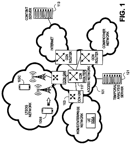
A method provides temporal caching in a content centric networking (CCN) network.
US 9,736,390 B2 · Assignee: Canon Kabushiki Kaisha · Inventors: Suzuki; Yasuo
Sheet 1 of 8 from the published document. All sheets in the USPTO PDF
An image processing apparatus according to the present invention includes: a first acquisition unit configured to acquire a first image; a second acquisition unit configured to acquire a second image; a characteristics acquisition unit configured to acquire characteristics information from the first image; a conversion unit configured to convert the first image to a third image by performing image processing in which a correspondence relationship of a gradation value and display brightness is made closer to a correspondence relationship in the second image, based on the characteristics information acquired by the characteristics acquisition unit; and a combination unit configured to generate a combined image by combining the second image and the third image.
Field of the Invention The present invention relates to an image processing apparatus and an image processing method. Description of the Related Art With increased digitalization of image production workflow in recent years, it has become possible to easily generate a combined image in which a captured image generated by capturing using an image capturing apparatus and a computer graphic image (hereinafter, “CG image”) are combined. Generation of a combined image is generally performed in post-production that is a step after a capturing step (step of performing capturing). Therefore, if there is a non-editable portion in a captured image at the time of generating a combined image, rework in the capturing step may occur. Thus, a method is often employed in which a combining apparatus that generates (simply generates) a combined image is brought to a capturing location to generate and chec
1 of 8 drawing sheets so far from the published document, cropped to the drawing. Every sheet is in the USPTO PDF.
What the patent claimed, word for word. All of it is now free to use.
Field of the Invention
The present invention relates to an image processing apparatus and an image processing method.
Description of the Related Art
With increased digitalization of image production workflow in recent years, it has become possible to easily generate a combined image in which a captured image generated by capturing using an image capturing apparatus and a computer graphic image (hereinafter, “CG image”) are combined.
Generation of a combined image is generally performed in post-production that is a step after a capturing step (step of performing capturing). Therefore, if there is a non-editable portion in a captured image at the time of generating a combined image, rework in the capturing step may occur.
Thus, a method is often employed in which a combining apparatus that generates (simply generates) a combined image is brought to a capturing location to generate and check a combined image at the capturing location. As the combining apparatus, a PC can be used, for example.
With such a method, a combined image can be checked (simply checked) in the capturing step, and the number of reworks in the capturing step can be reduced.
There are cases where the display brightness (brightness on screen) of a captured image differs greatly from the display brightness of a CG image.
In post-production, the display brightness of at least one of the captured image and the CG image is finely adjusted by an editor, so that the display brightness of the captured image is fit for the display brightness of the CG image.
However, since an editor is not always present at a capturing location, it is preferable that the display brightness of an image be automatically adjusted (simply adjusted) at a capturing location.
A technique of automatically adjusting the display brightness of an image is disclosed in Japanese Patent Application Laid-open No. 2005-142680, for example. In the technique disclosed in Japanese Patent Application Laid-open No. 2005-142680, the display brightness of each image is adjusted based on the average gradation value of one image, upon combining a plurality of images.
Along with the improvement in light-receiving performance of image capturing apparatuses in recent years, captured images having a wider dynamic range are being generated. As a data format for handling a captured image with a wider dynamic range, a data format having display characteristics (logarithmic characteristics) such that the display brightness changes logarithmically with respect to a change in the gradation value has been proposed. For example, at film production site, Cineon Log defined based on the characteristics of a film with a wide dynamic range is used as a data format.
On the other hand, a CG image generally has a narrow dynamic range. For example, BMP or JPEG is used as a data format for a CG image that is a still image, and JPEG 2000 is used as a data format of a CG image that is a video. The data formats cannot handle an image with a wide dynamic range, since the number of bits of a gradation value is 8 bits.
Therefore, there are cases where the dynamic range of a captured image and a dynamic range of a CG image greatly differ.
In the case where the dynamic ranges of a captured image and a CG image are the same, a suitable adjustment result (result of adjustment in the display brightness of an image) can be obtained by using the technique in Japanese Patent Application Laid-open No. 2005-142680.
However, in the case where the dynamic ranges of a captured image and a CG image are different, a suitable adjustment result cannot be obtained, even if the technique in Japanese Patent Application Laid-open No. 2005-142680 is used. For example, in the case of displaying a combined image in which an HDR image and an LDR image are combined, the display brightness of the HDR image cannot be made fit for the display brightness of the LDR image, even if the technique in Japanese Patent Application Laid-open No. 2005-142680 is used. An HDR image is an image with a wide dynamic range, e.g., a captured image. An LDR image is an image with a narrow dynamic range, e.g., a CG image.
An example of displaying a combined image in which an HDR image and an LDR image are combined will be described below.
As shown in FIG. 9 , the LDR image has display characteristics (linear characteristics) such that the display brightness changes linearly with respect to a change in the gradation value (LDR gradation value).
On the other hand, as shown in FIG. 10 , the HDR image has display characteristics (logarithmic characteristics) such that the display brightness changes logarithmically with respect to a change in the gradation value (HDR gradation value). The dynamic range of the HDR image is wider than that of the LDR image. The human vision is sensitive to a dark area, and it is preferable to allocate a narrow gradation range (range of gradation value) with respect to a range of low display brightness. Therefore, the logarithmic characteristics are frequently used as the display characteristics of an HDR image.
In FIGS. 9 and 10 , a gradation value corresponding to a light intensity value is used as the gradation value, in order to clarify the difference of dynamic ranges of the HDR image and the LDR image. The light intensity value is a value converted from a gradation value according to the reverse characteristics of the gradation characteristics that are a change in the gradation value with respect to a change in the light intensity value. In the case where an image is a captured image, the light intensity value is a value representing the brightness of light (brightness of a captured scene) received by an image sensor (CMOS sensor or the like) of an image capturing apparatus. In the case where the gradation characteristics are gamma characteristics, a value converted from a gradation value according to reverse gamma characteristics coincides with the light intensity value.
As shown in FIGS. 9 and 10 , the display brightness corresponding to the HDR gradation value differs from the display brightness corresponding to the LDR gradation value, even if the HDR gradation value and the LDR gradation value are equal. Therefore, a suitable adjustment result cannot be obtained, even if the technique in Japanese Patent Application Laid-open No. 2005-142680 is used. For example, the display brightness of the HDR image cannot be caused to coincide with the display brightness of the LDR image, even if the gradation value of the HDR image or the LDR image is adjusted such that the average gradation value of the HDR image coincides with the average gradation value of the LDR image.
The present invention provides a technique that enables suitable adjustment of the display brightness of a plurality of images, even in the case where the dynamic ranges of the plurality of images used for generating a combined image differ from each other.
The present invention in its first aspect provides an image processing apparatus comprising:
a first acquisition unit configured to acquire a first image;
a second acquisition unit configured to acquire a second image that is different in dynamic range from the first image;
a characteristics acquisition unit configured to acquire, from the first image, characteristics information representing at least one of a gradation value representing a bright area that is an area in the first image and is an area formed of a pixel with a gradation value greater than or equal to a first threshold value, and a size of the bright area;
a first conversion unit configured to convert the first image to a third image by performing image processing in which a correspondence relationship of a gradation value and display brightness is made closer to a correspondence relationship in the second image, based on the characteristics information acquired by the characteristics acquisition unit; and
a combination unit configured to generate a combined image by combining the second image and the third image.
The present invention in its second aspect provides an image processing method comprising:
a first acquisition step of acquiring a first image;
a second acquisition step of acquiring a second image that is different in dynamic range from the first image;
a characteristics acquisition step of acquiring, from the first image, characteristics information representing at least one of a gradation value representing a bright area that is an area in the first image and is an area formed of a pixel with a gradation value greater than or equal to a threshold value, and a size of the bright area;
a conversion step of converting the first image to a third image by performing image processing in which a correspondence relationship of a gradation value and display brightness is made closer to a correspondence relationship in the second image, based on the characteristics information acquired in the characteristics acquisition step; and
a combination step of generating a combined image by combining the second image and the third image.
The present invention in its third aspect provides a non-transitory computer readable medium that stores a program, wherein the program causes a computer to execute the image processing method.
With the pre sent invention, suitable adjustment of the display brightness of a plurality of images is made possible, even in the case where the dynamic ranges of the plurality of images used for generating a combined image differ from each other.
Further features of the present invention will become apparent from the following de script ion of exemplary embodiments with reference to the attached drawings.
FIG. 1 is a block diagram showing one example of the functional configuration of an image display apparatus according to Embodiment 1;
FIG. 2 is a diagram showing one example of chroma key processing according to Embodiment 1;
FIG. 3 is a diagram showing one example of a method of connection between apparatuses according to Embodiment 1;
FIG. 4 is a diagram showing one example of a method of determining the weight of HDR brightness conversion data according to Embodiment 1;
FIG. 5 is a diagram showing one example of LDR/HDR brightness conversion data according to Embodiment 1;
FIG. 6 is a diagram showing one example of a method of generating first brightness conversion data according to Embodiment 1;
FIG. 7 is a block diagram showing one example of the functional configuration of an image display apparatus according to Embodiment 2;
FIG. 8 is a diagram showing one example of first output processing according to Embodiment 2;
FIG. 9 is a diagram showing one example of the display characteristics of an LDR image; and
FIG. 10 is a diagram showing one example of the display characteristics of an HDR image.
<Embodiment 1>
An image processing apparatus and an image processing method according to Embodiment 1 of the present invention will be described below with reference to the drawings.
An example of a case where the image processing apparatus according to this embodiment is included in an image display apparatus will be described below. However, the image processing apparatus according to this embodiment may be an apparatus separate from the image display apparatus.
(Overall Configuration)
FIG. 1 is a block diagram showing one example of the functional configuration of an image display apparatus 100 according to this embodiment. As shown in FIG. 1 , the image display apparatus 100 includes a control unit 116 , a first gradation conversion unit 103 , a second gradation conversion unit 104 , a data selection unit 106 , a color space conversion unit 107 , an over-white area detection unit 108 , a weight determination unit 109 , a brightness conversion data generation unit 110 , a first brightness conversion unit 111 , a second brightness conversion unit 112 , an image combination unit 113 , a gamma conversion unit 114 , a display unit 115 , and the like.
As shown in FIG. 1 , the image display apparatus 100 is connected to an image capturing apparatus 180 and a recording apparatus 181 .
The control unit 116 controls each functional unit included in the image display apparatus 100 . In this embodiment, the control unit 116 sets the setting value used in each functional unit. Accordingly, processing in accordance with the setting value is executed in each functional unit. The setting value is, for example, read from a storage unit (such as a non-volatile memory) that is not shown and set. The setting value may be a fixed value set in advance by a manufacturer or the like or may be a value that can be changed by a user. The setting value may be generated and set based on captured image information 105 acquired from the image capturing apparatus 180 . The captured image information 105 includes, for example, a capturing parameter (ISO sensitivity, frame rate, shutter speed, white balance, or the like) used at the time of capturing for generating first image data 101 described later.
The first gradation conversion unit 103 acquires the first image data 101 from the image capturing apparatus 180 (as first acquisition processing). Specifically, the first gradation conversion unit 103 acquires the first image data 101 from the image capturing apparatus 180 using a serial digital interface (SDI) cable.
In this embodiment, the first image data 101 is captured image data generated by capturing using the image capturing apparatus 180 . The pixel value of the first image data 101 is an RGB value (a combination of an R value that is the gradation value of a red component, a G value that is the gradation value of a green component, and a B value that is the gradation value of a blue component). The gradation value (R value, G value, and B value) of the first image data 101 is a value of 10 bits that has undergone a logarithmic conversion. A “value that has undergone a logarithmic conversion” is a gradation value that has been converted using a logarithmic function from the gradation value in a reference unit. Hereinafter, the reference unit is referred to as “linear unit.”
By using a value that has undergone a logarithmic conversion, transmission of HDR image data with a wide dynamic range can be achieved easily.
The first gradation conversion unit 103 generates first linear image data 153 by converting the gradation value of the first image data 101 to a gradation value in linear unit. In this embodiment, the first linear image data 153 is generated by converting the gradation value of the first image data 101 according to a first conversion curve 151 set by the control unit 116 . The first conversion curve 151 is information (function or table) representing the correspondence relationship of the gradation value before conversion and the gradation value after conversion. The first gradation conversion unit 103 outputs the first linear image data 153 .
The first image data 101 and the first linear image data 153 are image data representing a first image.
A method of acquiring the first image data 101 is not limited to the method described above, and the first image data 101 is not limited to the data described above. For example, the first image data 101 may be acquired using a cable other than an SDI cable, or the first image data 101 may be acquired wirelessly. The pixel value of the first image data 101 may be a YCbCr value (a combination of a Y value that is a brightness value, a Cb value that is a color difference value, and a Cr value that is a color difference value). The number of bits of the gradation value of the first image data 101 may be greater than or smaller than 10 bits. The first image data 101 may not be captured image data. The first image data 101 may be acquired from an external apparatus (external apparatus for the image display apparatus 100 ) different from the image capturing apparatus 180 . The first image data 101 may be acquired from a storage unit (not shown) included in the image display apparatus 100 . The first linear image data 153 may be acquired from an external apparatus for the image display apparatus 100 , a storage unit included in the image display apparatus 100 , or the like, without performing processing of converting the gradation value.
The second gradation conversion unit 104 acquires second image data 102 from the recording apparatus 181 (as second acquisition processing). Specifically, the second gradation conversion unit 104 acquires the second image data 102 from the recording apparatus 181 using an SDI cable.
In this embodiment, the second image data 102 is computer graphic image data (CG image data) generated by a personal computer (PC). The pixel value of the second image data 102 is an RGB value. The gradation value of the second image data 102 is a value of 8 bits that has been converted with gamma characteristics (1/2.2 gamma characteristics) in which the gamma value is 1/2.2. A “value that has been converted with 1/2.2 gamma characteristics” is a gradation value that has been converted from the gradation value in linear unit according to the 1/2.2 gamma characteristics.
In the case where the second image data 102 is an LDR image data with a narrow dynamic range and is data of a still image, BMP or JPEG can be used as the data format of the second image data 102 . In the case where the second image data 102 is an LDR image data and is data of a video image, JPEG 2000 can be used as the data format of the second image data 102 .
The second gradation conversion unit 104 generates second linear image data 154 by converting the gradation value of the second image data 102 to a gradation value in linear unit. In this embodiment, the second linear image data 154 is generated by converting the gradation value of the second image data 102 according to a second conversion curve 152 set by the control unit 116 . The second conversion curve 152 is information (function or table) representing the correspondence relationship of the gradation value before conversion and the gradation value after conversion. The second gradation conversion unit 104 outputs the second linear image data 154 .
The second image data 102 and the second linear image data 154 are both image data representing a second image. In this embodiment, the dynamic range of the second image differs from the dynamic range of the first image. Specifically, the dynamic range of the second image is narrower than the dynamic range of the first image and is a part of the dynamic range of the first image.
A method of acquiring the second image data 102 is not limited to the method described above, and the second image data 102 is not limited to the data described above. For example, the second image data 102 may be acquired using a cable other than an SDI cable, or the second image data 102 may be acquired wirelessly. The pixel value of the second image data 102 may be a YCbCr value. The number of bits of the gradation value of the second image data 102 may be greater than or smaller than 8 bits. The second image data 102 may not be CG image data. The second image data 102 may be acquired from an external apparatus (external apparatus for the image display apparatus 100 ) different from the recording apparatus 181 . The second image data 102 may be acquired from a storage unit (not shown) included in the image display apparatus 100 . The second linear image data 154 may be acquired from an external apparatus for the image display apparatus 100 , a storage unit included in the image display apparatus 100 , or the like, without performing processing of converting the gradation value.
The dynamic range of the second image may be wider than the dynamic range of the first image. The dynamic range of the second image may include a gradation range not included in the dynamic range of the first image.
The data selection unit 106 selects one of the first linear image data 153 and the second linear image data 154 and outputs the selected image data. Specifically, the data selection unit 106 is input with an HDR image selection instruction 155 from the control unit 116 . In accordance with the HDR image selection instruction 155 , the data selection unit 106 selects, as HDR image data, image data with a wider dynamic range out of the first linear image data 153 and the second linear image data 154 and outputs the selected image data. In this embodiment, the first linear image data 153 is selected as the HDR image data.
The color space conversion unit 107 generates brightness data 156 by converting the RGB value of each pixel of the first linear image data 153 output from the data selection unit 106 to a Y value (data brightness value). Then, the color space conversion unit 107 outputs the brightness data 156 .
The over-white area detection unit 108 acquires, from the brightness data 156 , characteristics information representing the size of a bright area (over-white area) that is an area in the first image and is an area formed of pixels with a gradation value that is greater than or equal to a threshold value (first threshold value) (as characteristics acquisition processing). In this embodiment, over-white size rate data 158 representing the proportion of the total number of pixels of an over-white area with respect to the total number of pixels of the first image is acquired as the characteristics information for the size of the over-white area. Then, the over-white area detection unit 108 outputs the over-white size rate data 158 .
Specifically, the over-white area detection unit 108 first acquires a reference white brightness value 157 from the control unit 116 . The reference white brightness value 157 is a data brightness value at the boundary of a range of the data brightness value of a bright area and a range of the data brightness value for other areas.
Next, the over-white area detection unit 108 detects a pixel with a brightness value (data brightness value) that is greater than or equal to the reference white brightness value 157 out of a plurality of pixels of the brightness data 156 .
Then, the over-white area detection unit 108 calculates, as the over-white size rate, the proportion of the total number of detected pixels with respect to the total number of pixels of the brightness data 156 .
Next, the over-white area detection unit 108 generates the over-white size rate data 158 representing the calculated over-white size rate and outputs the over-white size rate data 158 .
In this manner, in this embodiment, the characteristics information is acquired from the first image by the color space conversion unit 107 and the over-white area detection unit 108 .
The reference white brightness value 157 may be a fixed value set in advance by a manufacturer or the like or may be a value that can be changed by a user.
The characteristics information may not be information representing the over-white size rate. For example, the characteristics information may be information representing the total number of pixels with a data brightness value that is greater than or equal to the reference white brightness value 157 .
In this embodiment, the first image is converted to a third image (as first conversion processing) based on the over-white size rate data 158 output from the over-white area detection unit 108 , by the weight determination unit 109 , the brightness conversion data generation unit 110 , and the first brightness conversion unit 111 . Specifically, the first linear image data 153 is converted to first brightness conversion image data 166 , based on the over-white size rate data 158 . In this embodiment, the first image is converted to the third image with a correspondence relationship of the gradation value and the display brightness (brightness on screen) that is closer to the correspondence relationship in the second image, as the size of a bright area (the over-white size rate represented by the over-white size rate data 158 ) is smaller.
The weight determination unit 109 generates weight information 160 representing the weight used by the brightness conversion data generation unit 110 in accordance with the over-white size rate data 158 output from the over-white area detection unit 108 . Specifically, the weight information 160 is generated to represent a greater weight for a greater over-white size rate (size of a bright area) represented by the over-white size rate data 158 . Then, the weight determination unit 109 outputs the weight information 160 .
The brightness conversion data generation unit 110 generates first brightness conversion data 164 and second brightness conversion data 165 , based on the weight information 160 output from the weight determination unit 109 . The first brightness conversion data 164 is data for converting the gradation value of the first linear image data 153 to a gradation value in the same unit as the display brightness. The second brightness conversion data 165 is data for converting the gradation value of the second linear image data 154 to a gradation value in the same unit as the display brightness. The first brightness conversion data 164 and the second brightness conversion data 165 are, for example, information (function or table) representing the correspondence relationship of the gradation value before conversion and the gradation value after conversion. Then, the brightness conversion data generation unit 110 outputs the first brightness conversion data 164 and the second brightness conversion data 165 .
In this embodiment, the brightness conversion data generation unit 110 acquires HDR brightness conversion data 161 that is initial data of the first brightness conversion data 164 and LDR brightness conversion data 162 that is initial data of the second brightness conversion data 165 from the control unit 116 . The HDR brightness conversion data 161 is data representing the correspondence relationship of the gradation value and the display brightness of the first image, and the LDR brightness conversion data 162 is data representing the correspondence relationship of the gradation value and the display brightness of the second image.
The brightness conversion data generation unit 110 generates the first brightness conversion data 164 by weighted combination of the HDR brightness conversion data 161 and the LDR brightness conversion data 162 with the weight represented by the weight information 160 . Specifically, the weight represented by the weight information 160 is used as the weight of the HDR brightness conversion data 161 . Then, the brightness conversion data generation unit 110 outputs the first brightness conversion data 164 .
The brightness conversion data generation unit 110 outputs the LDR brightness conversion data 162 as the second brightness conversion data 165 .
As the weight information 160 , information representing the weight of the LDR brightness conversion data 162 may be generated. As the weight information 160 , information individually representing the weight of the HDR brightness conversion data 161 and the weight of the LDR brightness conversion data 162 may be generated.
The first brightness conversion unit 111 generates the first brightness conversion image data 166 by converting the gradation value of the first linear image data 153 using the first brightness conversion data 164 . Then, the first brightness conversion unit 111 outputs the first brightness conversion image data 166 . The first brightness conversion image data 166 represents the third image. In the case where the first brightness conversion data 164 is equivalent to the HDR brightness conversion data 161 , the third image is equivalent to the first image. In the case where the first brightness conversion data 164 is different from the HDR brightness conversion data 161 , the third image is different from the first image.
The second brightness conversion unit 112 generates second brightness conversion image data 167 by converting the gradation value of the second linear image data 154 using the second brightness conversion data 165 . Then, the second brightness conversion unit 112 outputs the second brightness conversion image data 167 . As described above, the second brightness conversion data 165 is the LDR brightness conversion data 162 . Therefore, the second brightness conversion image data 167 represents the second image.
The image combination unit 113 generates a combined image by combining the third image and the second image. Specifically, the image combination unit 113 generates combined image data 168 representing the combined image by combining the first brightness conversion image data 166 and the second brightness conversion image data 167 . Then, the image combination unit 113 outputs the combined image data 168 .
In this embodiment, chroma key processing is performed as combination processing of combining image data. One example of the chroma key processing is shown in FIG. 2 .
First, a captured image (reference numeral 201 in FIG. 2 ) is generated by capturing an object (person or the like) in front of a green background (background such as a green cloth).
Next, a CG image (reference numeral 202 in FIG. 2 ) is generated with a PC or the like.
Then, by replacing the pixel values for an area of the green background among pixel values of the captured image with the pixel values for the CG image, a combined image (reference numeral 203 in FIG. 2 ) is generated.
The combination processing is not limited to the chroma key processing. For example, as the combination processing, alpha blending processing may be performed. In the alpha blending processing, the pixel value of a combined image is determined by combining the pixel value of one image and the pixel value of another image with a weight in accordance with a combination rate (alpha blending value). For example, the alpha blending value is determined with respect to each pixel of a CG image at the time of generating the CG image. Then, for a pixel with an alpha blending value of 0.3, the pixel value of the CG image is multiplied by the weight 0.3, and the pixel value of a captured image is multiplied by the weight 0.7. Then, by adding the two pixel values after multiplication with the weights, the pixel value of the combined image is calculated.
The gamma conversion unit 114 generates display image data 170 by converting the gradation value of the combined image data 168 to a driving gradation value according to the driving characteristics (correspondence relationship of the driving gradation value (gradation value for driving the display unit 115 ) and the display brightness) of the display unit 115 . Specifically, the gamma conversion unit 114 acquires driving characteristics information 169 representing the driving characteristics of the display unit 115 from the control unit 116 . Then, the gamma conversion unit 114 generates the display image data 170 by converting the gradation value of the combined image data 168 to the driving gradation value according to the driving characteristics represented by the driving characteristics information 169 .
The display image data 170 is also image data representing the combined image.
The driving characteristics of the display unit 115 changes depending on the type or the like of a display element included in the display unit 115 .
The display unit 115 displays an image based on the display image data 170 output from the gamma conversion unit 114 in a screen. Specifically, the display unit 115 includes a plurality of display elements arranged in a matrix. By respective display elements being driven in accordance with the display image data 170 , the image is displayed in a screen. As the display element, a liquid crystal element, an organic EL element, a plasma element, or the like can be used.
(Gradation Characteristics and Display Characteristics)
The gradation characteristics of each piece of image data used in this embodiment will be described below.
In this embodiment, the first image data 101 and the second image data 102 both have non-linear characteristics such that the gradation value changes non-linearly with respect to a change in the light intensity value. Specifically, the first image data 101 has gradation characteristics (logarithmic characteristics) such that the gradation value changes logarithmically with respect to a change in the light intensity value. The second image data 102 has gradation characteristics such that a change in the gradation value with respect to a change in the light intensity value shows 1/2.2 gamma characteristics. The light intensity value is a value converted from a gradation value according to the reverse characteristics of the gradation characteristics. In the case where image data is captured image data, the light intensity value is a value representing the brightness of light (brightness of a captured scene) received by an image sensor (CMOS sensor or the like) of the image capturing apparatus 180 .
In this embodiment, the range (dynamic range) of light intensity value that can be expressed with the first image data 101 is wider than the range of light intensity value that can be expressed with the second image data 102 .
In this embodiment, the first linear image data 153 and the second linear image data 154 both have linear characteristics such that the gradation value changes linearly with respect to a change in the light intensity value.
In this embodiment, the first brightness conversion image data 166 , the second brightness conversion image data 167 , and the combined image data 168 all have gradation characteristics such that the gradation value coincides with the display brightness. In other words, the first brightness conversion image data 166 , the second brightness conversion image data 167 , and the combined image data 168 all have display characteristics such that the display brightness changes linearly with respect to a change in the gradation value.
In this embodiment, the display image data 170 has display characteristics such that a change in the display brightness with respect to a change in the gradation value shows 1/2.2 gamma characteristics.
(Over-white Size Rate)
A specific method of determining the over-white size rate will be described.
For the sake of description, it is assumed below that the dynamic range of the first image data 101 is a dynamic range corresponding to 0 to 800% in light intensity value, and the gradation value of the first image data 101 is a 10-bit value. It is assumed that the dynamic range of the second image data 102 is a dynamic range corresponding to 0 to 100% in light intensity value, and the gradation value of the second image data 102 is an 8-bit value. It is assumed that the reference white brightness value is a data brightness value corresponding to 100% in light intensity value.
The first image data 101 , the second image data 102 , and the reference white brightness value are not limited to the data described above.
The first gradation conversion unit 103 converts the first image data 101 to the first linear image data 153 . Specifically, the gradation value (gradation value of the first image data 101 ) of which the gradation characteristics are logarithmic and the number of bits is 10 bits is converted to a gradation value of which the gradation characteristics are linear and the number of bits is 12 bits. Accordingly, the first image data 101 is converted to the first linear image data 153 .
The second gradation conversion unit 104 converts the second image data 102 to the second linear image data 154 . Specifically, the gradation value (gradation value of the second image data 102 ) of which the gradation characteristics are 1/2.2 gamma characteristics and the number of bits is 8 bits is converted to a gradation value of which the gradation characteristics are linear and the number of bits is 12 bits. Accordingly, the second image data 102 is converted to the second linear image data 154 .
The color space conversion unit 107 converts the RGB value of each pixel of the first linear image data 153 to a data brightness value (Y value). Accordingly, the first linear image data 153 is converted to the brightness data 156 . In this embodiment, an RGB value is converted to a Y value using the following formula 1. In formula 1, “Y” is a Y value, “R” is an R value, and “B” is a B value. Y= 0.299× R+ 0.587× G+ 0.114× B (Formula 1)
In this embodiment, a 12-bit R value, G value, and B value are converted to a 12-bit Y value.
The over-white area detection unit 108 determines the over-white size rate, based on the brightness data 156 .
As described above, in this embodiment, the data brightness value corresponding to 100% in light intensity value is used as the reference white brightness value. Therefore, in the case where the brightness data 156 is generated such that the Y value corresponding to 0% in light intensity value is 0 and the Y value corresponding to 800% in light intensity value is 4095, 512 is used as the reference white brightness value.
The over-white area detection unit 108 detects, as an over-white pixel (pixel of an over-white area), a pixel with a Y value that is greater than or equal to 512 and less than or equal to 4095 among a plurality of pixels of the brightness data 156 .
Then, the over-white area detection unit 108 determines (calculates) the over-white size rate using the following formula 2. In formula 2, “A” is the total number of pixels of the brightness data 156 , “B” is the total number of over-white pixels, and “C” is the over-white size rate. C =( B/A )×100 (Formula 2)
As the over-white size rate C, a value that is greater than or equal to 0% and less than or equal to 100% is obtained.
As described above, the reference white brightness value 157 may be a fixed value set in advance by a manufacturer or the like or may be a value that can be changed by a user. In the case where the reference white brightness value 157 is included in the captured image information 105 acquired from the image capturing apparatus 180 , the over-white size rate may be determined using the reference white brightness value 157 included in the captured image information 105 .
The captured image information 105 is acquired, for example, using a transmission path separate from that of the first image data 101 . For example, the first image data 101 is acquired using an SDI cable, and the captured image information 105 is acquired using a Universal Serial Bus (USB) cable. FIG. 3 shows one example of a connection method for the image capturing apparatus 180 , the recording apparatus 181 , and the image display apparatus 100 . In the example in FIG. 3 , the recording apparatus 181 and the image display apparatus 100 are connected to each other using an SDI cable. The image capturing apparatus 180 and the image display apparatus 100 are connected to each other using an SDI cable. The image capturing apparatus 180 and the image display apparatus 100 are connected to each other using a USB cable.
The captured image information 105 may be acquired using a cable other than a USB cable, or the captured image information 105 may be acquired wirelessly. The captured image information 105 may be acquired using the same transmission path as for the first image data 101 .
(First Brightness Conversion Data and Second Brightness Conversion Data)
Next, a specific method of generating the first brightness conversion data 164 and the second brightness conversion data 165 will be described.
The weight determination unit 109 determines the weight to be used upon weighted combination of the HDR brightness conversion data 161 and the LDR brightness conversion data 162 , in accordance with the over-white size rate data 158 . Then, the weight determination unit 109 outputs the weight information 160 representing the determined weight.
The description continues in the full USPTO document.
About 6,724 words. The USPTO PDF has it with every drawing.
Fees are due 3.5, 7.5 and 11.5 years after grant. This patent expired on August 15, 2025, so the fee marked "not paid" was the one that went unpaid.
IMAGE PROCESSING APPARATUS AND IMAGE PROCESSING METHOD
Filed Jul 2015 · published Jan 2016Image processing apparatus and image processing method
Filed Jul 2015 · granted Aug 2017Earlier publications, parents and continuations. None of them can still be enforced, or this patent would not be listed.
Prior art cited by the examiner or applicant. Useful when you check your own idea for novelty.
Everything on this page comes from the documents linked above.


