 Lapsed, fee not paid6 drawings
Hardware & Electronics · US 9,735,894 B2
High performance receiver architecture and methods thereof
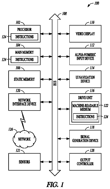
A user equipment (UE), receiver and method are generally described herein.
US 9,735,915 B2 · Assignee: NEC Corporation · Inventors: Satou; Yoshirou
Sheet 1 of 10 from the published document. All sheets in the USPTO PDF
[Objective] To make it possible to effectively relay remaining signals even when any input failure occurs on a propagation path. [Solution] Provided is an optical branching/insertion device including: a trunk-side detection/branching unit for detecting a failure of a trunk-side optical signal inputted from the trunk side and outputting it as a first detection result, and for splitting the trunk-side optical signal and sending the split signals respectively to the trunk side and to the branch side; a branch-side detection unit for detecting a failure of a branch-side optical signal inserted from the branch side and outputting it as a second detection result, and for sending the branch-side optical signal as an insertion signal; an insertion signal adjustment unit for outputting the insertion signal with its pass-through degree having been adjusted on the basis of the first detection result, as a first adjusted signal; a trunk signal adjustment unit for outputting the trunk-side optical signal with its pass-through degree having been adjusted on the basis of the first detection result, as a second adjusted signal; and a combining/output unit for outputting, to the outside, an optical signal into which the first adjusted signal and the second adjusted signal are combined together, as a trunk-side output optical signal.
In recent years, with the spread of the internet, demand for international telecommunications to process large-volume contents such as voices and video images has been rapidly increasing. Accordingly, optical wavelength division multiplexing communication, where a plurality of optical signals of different wavelengths are simultaneously transmitted on a single optical fiber cable, has been widely used as a high-speed and large-capacity information communication means. In particular, submarine cable systems are required to have very high reliability, because they are installed in deep sea and accordingly cannot be easily repaired. Because of this condition, research and development has been conducted on accuracy improvement and mutual interaction of a large number of relay devices intervening between the submarine cable systems. FIG. 10 is a block diagram showing a configuration diagram of
1 of 10 drawing sheets so far from the published document, cropped to the drawing. Every sheet is in the USPTO PDF.
What the patent claimed, word for word. All of it is now free to use.
This application is a National Stage Entry of International Application No. PCT/JP2014/000211, filed Jan. 17, 2014, which claims priority from Japanese Patent Application No. 2013-009831, filed Jan. 23, 2013. The entire contents of the above-referenced applications are expressly incorporated herein by reference.
The present invention relates to an optical relay device, and in particular, to an optical branching/insertion device which performs splitting and mixing of optical signals depending on specific wavelengths, an optical branching/insertion method for performing the same, and a recording medium.
In recent years, with the spread of the internet, demand for international telecommunications to process large-volume contents such as voices and video images has been rapidly increasing. Accordingly, optical wavelength division multiplexing communication, where a plurality of optical signals of different wavelengths are simultaneously transmitted on a single optical fiber cable, has been widely used as a high-speed and large-capacity information communication means.
In particular, submarine cable systems are required to have very high reliability, because they are installed in deep sea and accordingly cannot be easily repaired. Because of this condition, research and development has been conducted on accuracy improvement and mutual interaction of a large number of relay devices intervening between the submarine cable systems.
FIG. 10 is a block diagram showing a configuration diagram of a typical optical branching/insertion device 700 existing between submarine cable systems. The optical branching/insertion device 700 comprises an optical coupler 200 , an optical filter 400 , an optical filter 500 and an optical coupler 600 . The optical coupler 200 splits a trunk-side optical signal inputted from the outside and outputs the split signals respectively to the inside of the optical branching/insertion device 700 and to the brunch side. The optical filter 400 passes only a specific optical signal component (insertion signal) out of a brunch-side optical signal. The optical filter 500 passes only a specific optical signal component (pass-through signal) out of the trunk-side optical signal. The optical coupler 600 passes the specific optical signal component (insertion signal) out of the brunch-side optical signal, and combines the optical signal component thus passed with light outputted from the optical filter 500 .
However, in the above-described configuration, if an input failure of the trunk-side optical signal occurs, no pass-through signal is inputted to the optical branching/insertion device 700 . In that case, only an insertion signal is transmitted to the subsequent stage, and accordingly, there arises a problem of reduction in the total power. If an input failure of the brunch-side optical signal occurs, no insertion signal is inputted to the optical branching/insertion device 700 . In that case, only a pass-through signal is transmitted to the subsequent stage, and accordingly, there also arises a problem of reduction in the total power.
In terms of the problem described above, for example, PTL 1 and PTL 2 each describe a technology for making the total power of output light having been propagated through an optical fiber equivalent to that of the incident light.
In the technology of PTL 1, a total sum of powers of an optical signal inputted from a trunk line and that from a brunch line is compared with a threshold value set in advance. On the basis of the comparison result, the power of the input optical signal from the trunk line is controlled.
In the technology of PTL 2, when an optical input at the front stage of the device becomes in a no-input state owing to a transmission line failure or the like, inputted spontaneous emission light is adjusted to have the same level of output power as that of a pass-through optical signal in the ordinary state, and the adjusted light is outputted as compensation light. CITATION LIST Patent Literature
[PTL 1] Re-publication of PCT International Publication No. 2004/088893
[PTL 2] Japanese Patent Application Laid-Open No. 2006-66946 SUMMARY OF INVENTION Technical Problem
However, in an optical branching device of PTL 1, the power of an optical signal inputted from the trunk line is controlled on the basis of whether the level of the input signal falls within a range between two threshold values set in advance. Accordingly, the optical branching device has a problem of variation in the total power outputted to the outside, and also a problem of inability to adjust the input/output power on a per-wavelength basis.
An optical branching/insertion device disclosed in PTL 2 has a problem in that its overall configuration becomes complicated, and also a problem in that, if a failure occurs in inputting an optical signal to be inserted, only a pass-through optical signal or compensation light is outputted.
In general optical repeaters of submarine cable systems, constant excitation light control requiring a relatively simple circuit configuration is employed, instead of constant gain control. Therefore, even when the input power has become low, as a result of passing through some number of optical repeaters, the total output power becomes almost equal to that in the normal state.
Accordingly, in the technologies described in PTL 1 and PTL 2, it is anticipated that, when an input failure occurs, the transmission characteristics are degraded by a nonlinear effect which causes increase in the power per wavelength. An optical signal other than that for which the input failure has occurred is amplified to have a power exceeding an intended value. That is, there occurs an “optical nonlinear phenomenon” which is a phenomenon where the intensity of output light after propagation through an optical fiber is not proportional to the intensity of the incident light. The optical nonlinear phenomenon makes it impossible for the reception side to properly receive optical signals. Objective of Invention
The objective of the present invention is to provide an optical branching/insertion device, an optical branching/insertion method and a recording medium, all of which enable it to effectively relay remaining signals even when an input failure occurs. Solution to Problem
An optical branching/insertion device of the present invention comprises: a trunk-side detection/branching means which detects a failure of a trunk-side optical signal inputted from the trunk side and outputs it as a first detection result, and splits the trunk-side optical signal and sends the split signals respectively to the trunk side and to the branch side; a branch-side detection means which detects a failure of a branch-side optical signal inserted from the branch side and outputs it as a second detection result, and sends the branch-side optical signal as an insertion signal; an insertion signal adjustment device which outputs the insertion signal whose pass-through degree has been adjusted on the basis of the first detection result, as a first adjusted signal; a trunk signal adjustment device which outputs the trunk-side optical signal whose pass-through degree has been adjusted on the basis of the second detection result, as a second adjusted signal; and a combining/output means which outputs, to the outside, an optical signal into which the first adjusted signal and the second adjusted signal are combined together, as a trunk-side output optical signal.
An optical branching/insertion method of the present invention is characterized by that it comprises: detecting a failure of a trunk-side optical signal inputted from the trunk side and outputting it as a first detection result, and splitting the trunk-side optical signal and sending the split signals respectively to the trunk side and to the branch side; detecting a failure of a branch-side optical signal inserted from the branch side and outputting it as a second detection result, and sending the branch-side optical signal as an insertion signal; outputting the insertion signal whose pass-through degree has been adjusted on the basis of the first detection result, as a first adjusted signal; outputting the trunk-side optical signal whose pass-through degree has been adjusted on the basis of the second detection result, as a second adjusted signal; and outputting, to the outside, an optical signal into which the first adjusted signal and the second adjusted signal are combined together, as a trunk-side output optical signal.
A recording medium of the present invention stores an optical branching/insertion program for causing a computer to realize: a trunk-side detection/branching function to detect a failure of a trunk-side optical signal inputted from the trunk side and output it as a first detection result, and to split the trunk-side optical signal and send the split signals respectively to the trunk side and to the branch side; a branch-side detection function to detect a failure of a branch-side optical signal inserted from the branch side and output it as a second detection result, and to send the branch-side optical signal as an insertion signal; an insertion signal adjustment function to output the insertion signal whose pass-through degree has been adjusted on the basis of the first detection result, as a first adjusted signal; a trunk signal adjustment function to output the trunk-side optical signal whose pass-through degree has been adjusted on the basis of the second detection result, as a second adjusted signal; and a combining/output function to output, to the outside, an optical signal into which the first adjusted signal and the second adjusted signal are combined together, as a trunk-side output optical signal. Advantageous Effects of Invention
According to the present invention, even when an input failure occurs, remaining signals are effectively relayed.
FIG. 1 A block diagram showing an example of a basic configuration of an optical branching/insertion device according to a first exemplary embodiment of the present invention
FIG. 2 A block diagram showing an example of a specific configuration of the optical branching/insertion device shown in FIG. 1
FIG. 3 A block diagram showing an example of a network configuration of the optical branching/insertion device shown in FIGS. 1 and 2
FIG. 4 A diagram schematically showing flows of optical signals in a normal state, in the optical branching/insertion device shown in FIGS. 1 and 2
FIG. 5 A diagram schematically showing flows of optical signals in a state where a failure has occurred, in the optical branching/insertion device shown in FIGS. 1 and 2
FIG. 6 A flow chart showing an example of operation of the optical branching/insertion device shown in FIGS. 1 and 2
FIG. 7 A block diagram showing an example of a basic configuration of an optical branching/insertion device according to a second exemplary embodiment of the present invention
FIG. 8 A block diagram showing an example of a specific configuration of the optical branching/insertion device shown in FIG. 7
FIG. 9 A flow chart showing an example of operation of the optical branching/insertion device shown in FIGS. 7 and 8
FIG. 10 A block diagram showing a configuration of a typical optical branching/insertion device DESCRIPTION OF EMBODIMENTS First Exemplary Embodiment
A first exemplary embodiment of an optical branching/insertion device according to the present invention will be described, with reference to FIGS. 1 to 7 .
(Basic Configuration)
The optical branching/insertion device 71 according to the first exemplary embodiment comprises a trunk-side detection/branching means 21 , a branch-side detection means 31 , an insertion signal adjustment means 41 , a trunk signal adjustment means 51 and a combining/output means 61 .
The trunk-side detection/branching means 21 detects a failure of a trunk-side optical signal inputted from the trunk side and outputs it as a first detection result, and splits the trunk-side optical signal and outputs the split signals respectively to the trunk side and to the branch side.
The branch-side detection means 31 detects a failure of a branch-side optical signal inserted from the branch side and outputs it as a second detection result, and sends the branch-side optical signal as an insertion signal.
The insertion signal adjustment means 41 outputs the insertion signal whose pass-through degree has been adjusted on the basis of the first detection result, as a first adjusted signal.
The trunk signal adjustment means 51 outputs the trunk-side optical signal whose pass-through degree has been adjusted on the basis of the second detection result, as a second adjusted signal.
The combining/output means 61 outputs, to the outside, an optical signal into which the first adjusted signal and the second adjusted signal are combined together, as a trunk-side output optical signal.
When the second detection result indicates no failure occurrence of the branch-side optical signal, the trunk-signal adjustment means 51 passes only a signal component of a first specific wavelength out of the trunk-side optical signal. On the other hand, when the second detection result indicates any failure occurrence of the branch-side optical signal, the trunk-signal adjustment means 51 passes a signal component of a second specific wavelength, as well as that of the first specific wavelength, out of the trunk-side optical signal.
When the first detection result indicate no failure occurrence of the trunk-side optical signal, the insertion signal adjustment means 41 passes only a signal component of the second wavelength out of the insertion signal. On the other hand, when the first detection result indicates any failure occurrence of the trunk-side optical signal, the insertion signal adjustment means 41 passes a signal component of the first specific wavelength, as well as that of the second specific wavelength, out of the insertion signal.
(Specific Configuration)
Next, a specific configuration of the optical branching/insertion device 71 will be described, with reference to FIG. 2 .
The trunk-side detection/branching means 21 comprises an optical coupler 21 A, an optical coupler 21 B and an optical input interruption detection circuit (optical input interruption detection unit) 21 C.
The optical coupler 21 A splits a trunk-side optical signal and sends the split signals, respectively, into the direction where branching/passing is to be performed and into the direction where detection of an input failure (in the present exemplary embodiment, an “interruption of an input optical signal” is taken as an example) is to be performed (the direction of the optical input interruption detection circuit 21 C).
The optical coupler 21 B splits the trunk-side optical signal having passed through the optical coupler 21 A and sends the split signals, respectively, into the direction for branching (to the branch side) and into the direction for pass-through.
The optical input interruption detection circuit (optical input interruption detection unit) 21 C monitors the input power of the trunk-side optical signal, and thereby performs determination of whether or not any input interruption has been detected on the trunk-side propagation path. On detecting any input interruption, the optical input interruption detection circuit 21 C sends “trunk-side input interruption information” (the first detection result) to the insertion signal adjustment means 41 .
The branch-side detection means 31 comprises an optical coupler 31 A and an optical input interruption detection circuit (optical input interruption detection unit) 31 B.
The optical coupler 31 A splits a branch-side optical signal and sends the split signals, respectively, into the direction where insertion is to be performed and into the direction where detection of an optical input interruption is to be performed (the direction of the optical input interruption detection circuit 31 B).
The optical input interruption detection circuit 31 B monitors the input power of the branch-side optical signal, and thereby performs determination of whether or not any input interruption has been detected on the branch-side propagation path. On detecting any input interruption, the optical input interruption detection circuit 31 B sends “branch-side input interruption information” (the second detection result) to the trunk signal adjustment means 51 .
The insertion signal adjustment means 41 comprises an optical filter 41 A, an optical switch 41 B, an optical filter 41 C and an optical switch control circuit (optical switch control unit) 41 D.
The optical filter 41 A receives input of a branch-side optical signal (insertion signal) from the optical coupler 31 A at a port 7 , and then outputs a specific optical signal component (insertion light: a signal component having the second specific wave length) at a port 8 and the other optical signal component (insertion-prevented light: a signal component having the first specific wavelength) at a port 9 .
The optical switch 41 B performs passing/interception of the insertion-prevented light from the optical filter 41 A.
The optical filter 41 C is an optical filter with the same configuration as that of the optical filter 41 A, and is arranged in the reverse direction to that of the optical filter 41 A.
On receiving the trunk-side input interruption information, which is sent from the optical input interruption detection circuit 21 C when any input interruption has been detected, the optical switch control circuit 41 D sets the optical switch 41 B to the ON state.
The insertion light described above is outputted to the outside of the insertion signal adjustment means 41 via the ports 7 and 8 of the optical filter 41 A and ports 10 and 12 of the optical filter 41 C.
When the optical switch 41 B is in the ON state, the insertion-prevented light described above is outputted to the outside of the insertion signal adjustment means 41 via the ports 7 and 9 of the optical filter 41 A and ports 11 and 12 of the optical filter 41 C. On the other hand, when the optical switch 41 B is in the OFF state, the insertion-prevented light described above is intercepted by the optical switch 41 B, and accordingly is not outputted to the outside of the insertion signal adjustment means 41 .
The optical switch control circuit 41 D sends to the optical switch 41 B a power control signal relevant to passing/interception of an optical signal.
The optical input interruption detection circuit 21 C notifies the optical switch control circuit 41 D of the trunk-side input interruption information only when any input interruption has been detected. In other words, when no input interruption has been detected, the optical input interruption detection circuit 21 C notifies the optical switch control circuit 41 D of nothing. Accordingly, if no input interruption occurs, the optical switch 41 B is kept in the OFF state.
The trunk signal adjustment means 51 comprises an optical filter 51 A, an optical switch 51 B, an optical filter 51 C and an optical switch control circuit (optical switch control unit) 51 D.
The optical filter 51 A receives input of a trunk-side optical signal from the optical coupler 21 B at a port 1 , and then outputs a specific optical signal component (pass-through light: a signal component having the first specific wavelength) to a port 2 and the other optical signal component (pass-through-prevented light: a signal component having the second specific wavelength) to a port 3 .
The optical switch 51 B performs passing/interception of the pass-through-prevented light from the optical filter 51 .
The optical filter 51 C is an optical filter with the same configuration as that of the optical filter 51 A, and is arranged in the reverse direction to that of the optical filter 51 A.
On receiving the branch-side input interruption information, which is sent from the optical input interruption detection circuit 31 B when any input interruption has been detected, the optical switch control circuit 51 D sets the optical switch 51 B to the ON state.
The pass-through light described above is outputted to the outside of the trunk signal adjustment means 51 via the ports 1 and 2 of the optical filter 51 A, and ports 4 and 6 of the optical filter 51 C.
When the optical switch 51 B is in the ON state, the pass-through-prevented light described above is outputted to the outside of the trunk signal adjustment means 51 via the ports 1 and 3 of the optical filter 51 A, and ports 5 and 6 of the optical filter 51 C, and on the other hand, when the optical switch 51 B is in the OFF state, the pass-through-prevented light is intercepted by the optical switch 51 B, and accordingly is not outputted to the outside of the trunk signal adjustment means 51 .
The optical switch control circuit 51 D sends to the optical switch 51 B a power control signal relevant to passing/interception of an optical signal.
The optical input interruption detection circuit 31 B notifies the optical switch control circuit 51 D of the branch-side input interruption information only when any input interruption has been detected. In other words, when no input interruption has been detected, the optical input interruption detection circuit 31 B notifies the optical switch control circuit 51 D of nothing. Accordingly, if no input interruption occurs, the optical switch 51 B is kept in the OFF state.
The combining/output means 61 comprises an optical coupler 61 A which receives input of an optical signal having passed through the optical filter 51 C and that having passed through the optical filter 41 C, and then combines the signals together and outputs the combined signal.
That is, the optical filter 51 C combines pass-through light inputted from the port 4 with pass-through-prevented light inputted as necessary from the port 5 (the pass-through-prevented light is passed only when the optical switch 51 B is in the ON state), and outputs the combined light to the optical coupler 61 A.
On the other hand, the optical filter 41 C combines insertion light inputted from the port 10 with insertion-prevented light inputted as necessary from the port 11 (the insertion-prevented light is passed only when the optical switch 41 B is in the ON state), and outputs the combined light to the optical coupler 61 A.
In the first exemplary embodiment, optical couplers which are devices for performing coupling or branching on a plurality of optical fibers are employed as components of the optical branching/insertion device 71 , as has been described above. That is, the optical coupler 21 A performs a function to branch a trunk-side optical signal and output the branch signal to the branch side. The optical coupler 61 A performs a function to combine a pass-through signal component out of a trunk-side optical signal with an insertion signal component out of a branch-side optical signal and output the combined signal.
The optical switch control circuit 41 D controls the optical switch 41 B on the basis of a result of input interruption detection by the optical input interruption detection circuit 21 C. Accordingly, because the pass-through degree with respect to an optical signal on the trunk side is adjusted, even when any input interruption has occurred on the trunk side, insertion light corresponding to the remaining signal is effectively propagated.
Similarly, the optical switch control circuit 51 D controls the optical switch 51 B on the basis of a result of input interruption detection by the optical input interruption detection circuit 31 B. Accordingly, because the pass-through degree with respect to an optical signal on the trunk side is adjusted, even when any input interruption occurs on the branch side, pass-through light corresponding to the remaining signal is effectively propagated.
(Network Configuration)
FIG. 3 is a diagram showing a network configuration including the optical branching/insertion device 71 according to the first exemplary embodiment, where upward and downward directions are expediently defined.
The configurations of G- 1 and G- 2 , which are arranged respectively in the upward and downward directions and collectively as an optical branching/insertion device G, are the same as that of the optical branching/insertion device 71 described above. That is, FIGS. 1 and 2 correspond to diagrams showing the contents of the configuration of the optical branching/insertion device G- 1 . Accordingly, the present description will be continued in particular with respect to the upward direction in FIG. 3 , and a description of the downward direction having the same configuration will be omitted.
The network comprises optical terminal station devices A and B as trunk stations, optical repeaters D, E and F each consisting of an optical amplifier or the like, an optical terminal station device C as a branch station, and the optical branching/insertion device G.
As mentioned above, the optical branching/insertion device G comprises G- 1 and G- 2 , each having the same configuration as that of the optical branching/insertion device 71 , respectively in the upward and downward directions. The optical terminal station device C comprises C- 1 as a branch station operating with the optical branching/insertion device G- 1 and C- 2 as a branch station operating with the optical branching/insertion device G- 2 .
The optical repeaters D and E comprise D- 1 and D- 2 , and E- 1 and E- 2 , respectively, in respective ones of the upward and downward directions.
The optical repeater F comprises F- 1 for relaying a branch signal from the optical branching/insertion device G- 1 , F- 2 for relaying an insertion signal from the optical terminal station device C- 1 , F- 4 for relaying a branch signal from the optical branching/insertion device G- 2 and F- 3 for relaying an insertion signal from the optical terminal station device C- 2 .
Wavelength-multiplexed light outputted from the optical terminal station device A passes through the optical repeater D- 1 and then is inputted to the optical branching/insertion device G- 1 . In G- 1 , the wavelength-multiplexed light is split to the trunk side and the branch side. On the trunk side, a signal component of a specific wavelength (pass-through light) is passed out of the wavelength-multiplexed light. Also in the optical branching/insertion device G- 1 , the pass-through signal (pass-through light) on the trunk side is combined with an insertion signal (insertion light) from the branch side. The combined signal is propagated to the opposing optical terminal station device B via the optical repeater E- 1 .
(Flow of Optical Signals)
Next, on the basis of the above-described network configuration, flows of optical signals in the optical branching/insertion device (submarine optical branching/insertion device) G- 1 will be described, with reference to FIGS. 4 and 5 . Here, FIGS. 1 and 2 are referred to in terms of constituent members of the optical branching/insertion device G- 1 (Optical branching/insertion device 71 ).
Here, a flow of optical signals in the normal state will be described first, with reference to FIG. 4 .
In the first exemplary embodiment, a trunk-side optical signal including optical signal components of two wavelengths to branch out (branch light) and optical signal components of four wavelengths to pass through (pass-through light), as shown by ( 1 ) in FIG. 4 , is inputted to the trunk-side detection/branching means 21 of the optical branching/insertion device G- 1 .
The trunk-side detection/branching means 21 having received the trunk-side optical signal firstly outputs the branch light to the branch side, as shown by ( 2 ) in FIG. 4 , by means of the optical coupler 21 B. Although the trunk-side detection/branching means 21 performs no filtering, and accordingly also the optical signal components to pass through (pass-through light) branches out, the signal components are not terminated at the opposing optical terminal station device C and accordingly cause no problem.
Next, as shown by ( 3 ) in FIG. 4 , the trunk signal adjustment means 51 of the optical branching/insertion device G- 1 causes necessary signal components (pass-through light) to pass through it via the optical filters 51 A and 51 C, and intercepts unnecessary signal components (here, the branch light) by means of the optical switch 51 B in the OFF state.
Subsequently, a branch-side optical signal including optical signal components of two wavelengths to insert (insertion light) and dummy light for power compensation of two wavelengths consisting of a shorter wavelength side signal component and a longer wavelength side one, as shown by ( 4 ) in FIG. 4 , is inputted to the branch-side detection means 31 of the optical branching/insertion device G- 1 .
Next, the insertion signal adjustment means 41 of the submarine optical branching/insertion device G- 1 causes necessary signal components (insertion light) to pass through it via the optical filters 41 A and 41 C, and intercepts unnecessary signal components (here, the dummy light), as shown by ( 5 ) in FIG. 4 , by means of the optical switch 41 B in the OFF state. That is, the dummy light, which is unnecessary in the normal state, is intercepted here.
Finally, as shown by ( 6 ) in FIG. 4 , the optical signal components on the pass-through signal side (pass-through light) and those on the insertion signal side (insertion light) are combined together and then outputted, by the optical coupler 61 A as the combining/output means 62 . That is, an optical signal having a predetermined power is outputted from the optical branching/insertion device G- 1 to the outside.
Next, a flow of optical signals in a failure state (in a case of a forward failure of the optical repeater D- 1 ) will be described, with reference to FIG. 5 .
As shown by ( 1 ) in FIG. 5 , a trunk-side optical signal is, similarly to that in the normal state, an optical signal including optical signal components to branch out (branch light) consisting of two wavelength components and optical signal components to pass through (pass-through light) consisting of four wavelength components. That is, the trunk-side optical signal including the optical signals of two wavelengths to branch out (branch light) and the optical signals of four wavelength to pass through (pass-through light) is propagated up to a point just before a point of failure occurrence preceding the optical repeater (submarine optical repeater) D- 1 . However, in the presently assumed situation, a cable failure has occurred before the optical repeater D- 1 , and therefore, the optical repeater D- 1 outputs spontaneous emission light to the subsequent device.
Accordingly, the spontaneous emission light having lost the signal components owing to the cable failure is inputted to the trunk-side detection/branching means 21 of the optical branching/insertion device G- 1 , and therefore, a branch signal outputted to the branch side by the optical coupler 21 B becomes equal to the spontaneous emission light having lost the signal components, as shown by ( 2 ) in FIG. 5 .
Next, the trunk signal adjustment means 51 of the optical branching/insertion device G- 1 outputs, instead of the optical signal components to pass through in the normal state (refer to FIG. 4 ( 3 )), spontaneous emission light extracted into a filtered shape by the optical filters 51 A and 51 C, as shown by ( 3 ) in FIG. 5 .
Subsequently, a branch-side optical signal including optical signal components to insert (insertion light) consisting of two wavelength components and dummy light for power compensation of two wavelengths consisting of a shorter wavelength side signal component and a longer wavelength side one, as shown by ( 4 ) in FIG. 5 , is inputted to the branch-side detection means 31 of the optical branching/insertion device G- 1 .
Next, the insertion signal adjustment means 42 of the optical branching/insertion device G- 1 causes necessary signal components (insertion light) to pass through it via the optical filters 41 A and 41 C, and also causes the optical signal components having been intercepted (in this case, the dummy light) to pass through it, as compensation light for power compensation, via the optical switch 41 B having been set to the ON state by the optical switch control circuit 41 D, as shown by ( 5 ) in FIG. 5 .
Finally, the spontaneous emission light on the pass-through side is combined with the optical signal components and compensation light on the insertion side by the optical coupler 61 A as the combining/output means 61 , as shown by ( 6 ) in FIG. 5 . That is, although signal components other than the ones thus inserted have been lost, the power of the spontaneous emission light is supplemented by the compensation light. Accordingly, an optical signal having a predetermined significant power is outputted from the optical branching/insertion device G- 1 to the outside.
(Description of Operation)
Next, operation of the optical branching/insertion device 71 shown in FIGS. 1 and 2 will be described, with reference to a flow chart shown in FIG. 6 .
[Operation Based on Trunk-Side Optical Signal]
First, the optical coupler 21 A receives input of a trunk-side optical signal from the outside ( FIG. 6 : S 601 ). The optical coupler 21 A splits the trunk-side optical signal into two directions, one of which is on the side of the optical coupler 21 B and the other is on the side of the optical input interruption detection circuit 21 C ( FIG. 6 : S 602 ).
The optical coupler 21 B splits the optical signal received from the optical coupler 21 A into two directions, one of which is on the side of the optical filter 51 A and the other is on the branch side ( FIG. 6 : S 603 ).
On the basis of the optical signal received from the optical coupler 21 A, the optical input interruption detection circuit 21 C determines whether or not any input interruption has occurred on the trunk side propagation path ( FIG. 6 : S 604 ).
If any input interruption has occurred ( FIG. 6 : YES at S 604 ), the optical input interruption detection circuit 21 C sends trunk-side input interruption information to the optical switch control circuit 41 D ( FIG. 6 : S 605 ).
The optical switch control circuit 41 D having received the trunk-side input interruption information sets the optical switch 41 B to the ON state ( FIG. 6 : S 606 ).
On the other hand, if no input interruption has occurred ( FIG. 6 : NO at S 604 ), the optical switch 41 B is kept in the OFF state.
[Operation Based on Branch-Side Optical Signal]
From the branch side, an optical signal to insert is inputted, along with dummy light, to the optical coupler 31 A ( FIG. 6 : S 607 ). The optical coupler 31 A splits the inputted optical signal into two directions, one of which is on the side of the optical filter 41 A and the other is on the side of the optical input interruption detection circuit 31 B ( FIG. 6 : S 608 ).
On the basis of the optical signal received from the optical coupler 31 A, the optical input interruption detection circuit 31 B determines whether or not any input interruption has occurred on the branch side propagation path ( FIG. 6 : S 609 ).
If any input interruption has occurred ( FIG. 6 : YES at S 609 ), the optical input interruption detection circuit 31 B sends branch-side input interruption information to the optical switch control circuit 51 D ( FIG. 6 : S 610 ).
The optical switch control circuit 51 D having received the branch-side input interruption information sets the optical switch 51 B to the ON state ( FIG. 6 : S 611 ).
On the other hand, if no input interruption has occurred ( FIG. 6 : NO at S 609 ), the optical switch 51 B is kept in the OFF state.
[Optical Signal Passing Process Based on Adjusted Pass-Through Degree]
The optical filter 51 A sends the optical signal received from the optical coupler 21 B ( FIG. 6 : S 603 and S 609 to S 611 ) to the optical filter 51 C ( FIG. 6 : S 612 ).
Specifically, when any input interruption has been detected by the optical input interruption detection circuit 31 B ( FIG. 6 : YES at S 609 ), the optical switch control circuit 51 D sets the optical switch 51 B to the ON state. Accordingly, to the optical filter 51 C, the pass-through-prevented light for supplementing the branch-side optical signal is sent via the optical switch 51 B, as well as the pass-through light.
On the other hand, when no input interruption has been detected by the optical input interruption detection circuit 31 B ( FIG. 6 : NO at S 609 ), the optical switch 51 B is kept in the OFF state. Accordingly, only the pass-through light is sent to the optical filter 51 C.
Similarly, the optical filter 41 A sends the optical signal received from the optical coupler 31 A ( FIG. 6 : S 608 and S 604 to S 606 ) to the optical filter 41 C ( FIG. 6 : S 613 ).
Specifically, when any input interruption has been detected by the optical input interruption detection circuit 21 C ( FIG. 6 : YES at S 604 ), the optical switch control circuit 41 D sets the optical switch 51 B to the ON state. Accordingly, to the optical filter 41 C, the insertion-prevented light for supplementing the trunk-side optical signal (compensation light) is sent via the optical switch 41 B, as well as the insertion light ( FIG. 6 : S 613 ).
On the one hand, when no input interruption has been detected by the optical input interruption detection circuit 21 C ( FIG. 6 : NO at S 604 ), the optical switch 41 B is kept in the OFF state. Accordingly, only the insertion light is sent to the optical filter 41 C ( FIG. 6 : S 613 ).
The optical coupler 61 A combines the optical signals received respectively from the optical filters 51 C and 41 C, and then sends the combined signal to the outside ( FIG. 6 : S 614 ).
Although the above description of operation has been made, for convenience, in numerical order according to the numbers assigned in FIG. 6 (S 601 to S 614 ), contents of operation of the optical branching/insertion device 71 according to the first exemplary embodiment is not limited to that order.
Further, the configuration may be such that the contents to be performed in the respective processes corresponding to the steps S 601 to S 614 ( FIG. 6 ) described above are programmed, and the series of control programs are realized by a computer (including, for example, a logic device, a CPU (Central Processing Unit) and the like).
The above-described programs are delivered, for example, by being stored in a computer readable non-transitory recording medium such as a flexible disk, a CD-ROM (Compact Disk Read-Only Memory) and an MO (Magneto-Optical disk), or via a network. Effect of First Exemplary Embodiment
In the optical branching/insertion device 71 according to the first exemplary embodiment, branching and passing of a trunk-side optical signal and insertion of a branch-side optical signal are performed by the optical couplers 21 B and 61 A, the optical filters 41 A, 41 C, 51 A and 51 C and the like. It accordingly can perform an OADM (Optical Add/Drop Multiplexer) function in a submarine cable system.
Further, when an input failure of a trunk-side optical signal is detected, the state of the optical switch 41 B is changed from OFF to ON. Accordingly, an optical signal component, out of a branch-side optical signal, which have been intercepted (insertion-prevented light) comes to be outputted as compensation light for the optical signal (pass-through light) having been lost. As a result, variation in the insertion signal power caused by an input failure is suppressed.
The description continues in the full USPTO document.
About 6,550 words. The USPTO PDF has it with every drawing.
Fees are due 3.5, 7.5 and 11.5 years after grant. This patent expired on August 15, 2025, so the fee marked "not paid" was the one that went unpaid.
OPTICAL BRANCHING/INSERTION DEVICE, OPTICAL BRANCHING/INSERTION METHOD AND RECORDING MEDIUM
Filed Jan 2014 · published Dec 2015Optical branching/insertion device, optical branching/insertion method and recording medium
Filed Jan 2014 · granted Aug 2017Earlier publications, parents and continuations. None of them can still be enforced, or this patent would not be listed.
Prior art cited by the examiner or applicant. Useful when you check your own idea for novelty.
Everything on this page comes from the documents linked above.


