Technical field
An embodiment of the present invention relates generally to a computing system, and more particularly to a system with command-sense mechanism.
Background
Modern consumer and industrial electronics, especially devices such as graphical computing systems, televisions, cellular phones, portable digital assistants, and combination devices, are providing increasing levels of functionality to support modern life including access to user applications. Research and development in the existing technologies can take a myriad of different directions.
As users become more empowered with the growth of computing systems, new and old paradigms begin to take advantage of this new device space. One such advancement has been accessing or controlling multiple devices. However, the rapid growth in consumer electronics and the integration of access and control across multiple devices have presented new challenges for the users.
Thus, a need still remains for a computing system with command-sense mechanism. In view of the ever-increasing commercial competitive pressures, along with growing consumer expectations and the diminishing opportunities for meaningful product differentiation in the marketplace, it is increasingly critical that answers be found to these problems. Additionally, the need to reduce costs, improve efficiencies and performance, and meet competitive pressures adds an even greater urgency to the critical necessity for finding answers to these problems.
Solutions to these problems have been long sought but prior developments have not taught or suggested any solutions and, thus, solutions to these problems have long eluded those skilled in the art.
Summary
An embodiment of the present invention provides a computing system, including: an input-output unit configured to identify a tone-detection result for representing a transmission tone received at a device; a control unit, coupled to the input-output unit, configured to: determine a wave-detection profile including a frequency shift based on the tone-detection result, calculate a command-movement direction based on the wave-detection profile for representing the command-movement direction relative to the device and a further device, and identify a gesture command based on the command-movement direction for operating the device relative to the further device including displaying on the device.
An embodiment of the present invention provides a method of operation of a computing system including: identifying a tone-detection result for representing a transmission tone received at a device; determining a wave-detection profile including a frequency shift based on the tone-detection result; calculating a command-movement direction based on the wave-detection profile for representing the command-movement direction relative to the device and a further device; and identifying a gesture command based on the command-movement direction for operating the device relative to the further device including displaying on the device.
An embodiment of the present invention provides a non-transitory computer readable medium including instructions for operating a computing system including: identifying a tone-detection result for representing a transmission tone received at a device; determining a wave-detection profile including a frequency shift based on the tone-detection result; calculating a command-movement direction based on the wave-detection profile for representing the command-movement direction relative to the device and a further device; and identifying a gesture command based on the command-movement direction for operating the device relative to the further device including displaying on the device.
Certain embodiments of the invention have other steps or elements in addition to or in place of those mentioned above. The steps or elements will become apparent to those skilled in the art from a reading of the following detailed description when taken with reference to the accompanying drawings.
Brief description of the drawings
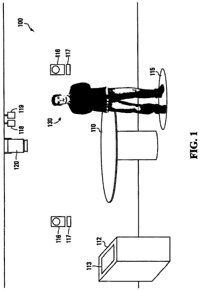
FIG. 1 is a computing system with command sense mechanism in an embodiment of the present invention.
FIG. 2 is an example illustration of the computing system.
FIG. 3 is an example illustration of the wave-detection profile.
FIG. 4 is an example display of the first device.
FIG. 5 is an example block diagram of the computing system.
FIG. 6 is a further functional block diagram of the computing system.
FIG. 7 is a further functional block diagram of the computing system.
FIG. 8 is a control flow of the computing system.
Detailed description
The following embodiments of the present invention can be used to allow a user to select one or more devices and share contents with a command movement corresponding to a simple movement. To create a connection between the devices, the user can use bodily movement from his device to the other device.
The embodiments of the present invention can generate a transmission tone. The transmission tone can react to the command movement and result in a frequency shift, captured and analyzed through atone-detection result and a wave-detection profile. The embodiments of the present invention can execute a gesture command corresponding to the command movement.
The transmission tone, the frequency shift detected for representing the command movement, and the gesture command associated thereto can provide increased functionality and simpler user interface for sharing or transfer data between devices in multiple device environment. The transmission tone generated based on a contextual factor or the associated instance of the gesture context provides increased usability and increased battery life. The command-movement direction based on the wave-detection profile provides increased usability.
The following embodiments are described in sufficient detail to enable those skilled in the art to make and use the invention. It is to be understood that other embodiments would be evident based on the present disclosure, and that system, process, or mechanical changes may be made without departing from the scope of an embodiment of the present invention.
In the following description, numerous specific details are given to provide a thorough understanding of the invention. However, it will be apparent that the invention may be practiced without these specific details. In order to avoid obscuring an embodiment of the present invention, some well-known circuits, system configurations, and process steps are not disclosed in detail.
The drawings showing embodiments of the system are semi-diagrammatic, and not to scale and, particularly, some of the dimensions are for the clarity of presentation and are shown exaggerated in the drawing figures. Similarly, although the views in the drawings for ease of description generally show similar orientations, this depiction in the figures is arbitrary for the most part. Generally, the invention can be operated in any orientation. The embodiments have been numbered first embodiment, second embodiment, etc. as a matter of descriptive convenience and are not intended to have any other significance or provide limitations for an embodiment of the present invention.
The term “module” referred to herein can include or be implemented as software, hardware, or a combination thereof in the present invention in accordance with the context in which the term is used. For example, the software can be machine code, firmware, embedded code, and application software. The software can also include a function, a call to a function, a code block, or a combination thereof. Also for example, the hardware can be gates, circuitry, processor, computer, integrated circuit, integrated circuit cores, a pressure sensor, an inertial sensor, a microelectromechanical system (MEMS), passive devices, physical non-transitory memory medium having instructions for performing the software function, a portion therein, or a combination thereof.
The term “processing” as used herein includes filtering signals, decoding symbols, assembling data structures, transferring data structures, manipulating data structures, and reading and writing data structures. Data structures are defined to be information arranged as symbols, packets, blocks, files, input data, system generated data, such as calculated or generated data, and program data.
Referring now to FIG. 1 , therein is shown a computing system 100 with command sense mechanism in an embodiment of the present invention. The computing system 100 includes a first device 102 , such as a mobile device including a cellular phone or a notebook computer, connected to a network 104 .
The first device 102 can be a client or a server. For example, the first device 102 can be of any of a variety of devices, such as a smartphone, a cellular phone, personal digital assistant, a tablet computer, a notebook computer, or other multi-functional display or entertainment device. The first device 102 can couple, either directly or indirectly, to the network 104 for exchanging information with other devices.
The network 104 is a system of wired or wireless communication devices that are connected to each other for enabling communication between devices. For example, the network 104 can include a combination of wires, transmitters, receivers, antennas, towers, stations, repeaters, telephone network, servers, or client devices for a wireless cellular network. The network 104 can also include a combination of routers, cables, computers, servers, and client devices for various sized area networks.
The network 104 can span and represent a variety of network types and network topologies. For example, the network 104 can include wireless communication, wired communication, optical, ultrasonic, or the combination thereof. Satellite communication, cellular communication, Bluetooth, Infrared Data Association standard (IrDA), wireless fidelity (WiFi), and worldwide interoperability for microwave access (WiMAX) are examples of wireless communication that can be included in the network 104 . Ethernet, digital subscriber line (DSL), fiber to the home (FTTH), and plain old telephone service (POTS) are examples of wired communication that can be included in the network 104 . Further, the network 104 can traverse a number of network topologies and distances. For example, the network 104 can include direct connection, personal area network (PAN), local area network (LAN), metropolitan area network (MAN), wide area network (WAN), or a combination thereof.
Device users (not shown) can communicate with each other or access or create information using devices including text, images, symbols, location information, and audio, as examples. The users can be individuals or enterprise companies. The information can be created directly from a user or operations performed on these information to create more or different information.
The network 104 can include a second device 106 for directly linking and communicating with the first device 102 . The second device 106 can receive wireless signals from the first device 102 , transmit signals to the first device 102 , process signals, or a combination thereof. The second device 106 can also relay signals between other base stations, components within the network 104 , or a combination thereof.
The second device 106 can be any of a variety of centralized or decentralized computing devices. For example, the second device 106 can be a multimedia computer, a laptop computer, a desktop computer, a video game console, grid-computing resources, a virtualized computer resource, cloud computing resource, routers, switches, peer-to-peer distributed computing devices, a media playback device, a recording device, such as a camera or video camera, or a combination thereof. In another example, the second device 106 can be a server at a service provider or a computing device at a transmission facility.
For illustrative purposes, the computing system 100 is described with the first device 102 as a consumer device or a portable device, and with the second device 106 as a stationary or an enterprise device. However, it is understood that the first device 102 and the second device 106 can be any variety of devices. For example, the first device 102 can be a stationary device or an enterprise system, such as a television or a server. Also for example, the second device 106 can be a consumer device or a portable device, such as a smart phone or a wearable device.
The first device 102 can connect to and communicate with other devices, such as other mobile devices, servers, computers, telephones, or a combination thereof. For example, the first device 102 can communicate with other devices by transmitting signals, receiving signals, processing signals, or a combination thereof and displaying a content of the signals, audibly recreating sounds according to the content of the signals, processing according to the content, such as storing an application or updating an operating system, or a combination thereof.
The computing system 100 can include a third device 108 , a fourth device 110 , or a combination thereof. The third device 108 , the fourth device 110 , or a combination thereof can be a client or a server. The third device 108 , the fourth device 110 , or a combination thereof can be similar to the first device 102 , the second device 106 , or a combination thereof. The computing system 100 can include a multiple device environment (MDE).
For example, the third device 108 , the fourth device 110 , or a combination thereof can be of any of a variety of devices, such as a smartphone, a cellular phone, personal digital assistant, a tablet computer, a notebook computer, a multimedia computer, a laptop computer, a desktop computer, a video game console, other multi-functional display or entertainment device, grid-computing resources, a virtualized computer resource, cloud computing resource, routers, switches, peer-to-peer distributed computing devices, a media playback device, a recording device, such as a camera or video camera, or a combination thereof. The first device 102 , the second device 106 , the third device 108 , the fourth device 110 , or a combination thereof can couple, either directly or indirectly, to the network 104 for exchanging information with each other or other devices.
For illustrative purposes, the computing system 100 is described with the first device 102 as a portable multi-functional device, although it is understood that the first device 102 can be different types of devices. For example, the first device 102 can also be a workstation or a multi-media presentation. A multi-media presentation can be a presentation including sound, a sequence of streaming images or a video feed, text or a combination thereof.
Also for illustrative purposes, the computing system 100 is described with the third device 108 and the fourth device 110 as personal devices, although it is understood that the third device 108 , the fourth device 110 , or a combination thereof can be different types of devices. For example, the third device 108 , the fourth device 110 , or a combination thereof can be a shared device, a public device, a corporate device assigned to an individual user or a group, or a combination thereof. Also for example, the third device 108 , the fourth device 110 , or a combination thereof can be owned by one user same as the first device 102 or different from the owner of the first device 102 .
For further illustrative purposes, the computing system 100 is described with the second device 106 as a computing device and as a server, although it is understood that the second device 106 can be different types of devices as described above. Also for illustrative purposes, the computing system 100 is shown with the second device 106 , the first device 102 , the third device 108 , and the fourth device 110 as end points of the network 104 , although it is understood that the computing system 100 can have a different partition between the first device 102 , the second device 106 , the third device 108 , the fourth device 110 , and the network 104 . For example, the first device 102 , the second device 106 , the third device 108 , the fourth device 110 , or a combination thereof can also function as part of the network 104 .
Referring now to FIG. 2 , therein is shown an example illustration of the computing system 100 . As an example, the computing system 100 can include the first device 102 , the third device 108 to the right of the first device 102 and the fourth device 110 to the left of the first device 102 .
One or more devices in the computing system 100 can generate or communicate a transmission tone 202 . The transmission tone 202 is information transmitted for communication between devices using a transmission frequency, a transmission bandwidth, or a combination thereof. The transmission tone 202 can be a wave, such as for wireless signals or sounds. The transmission tone 202 can include a specific frequency for the wave.
For example, the one or more devices can generate or transmit the transmission tone 202 using a speaker, a transmitter, or a combination thereof integrated in or connected to the one or more devices. Also for example, the one or more devices receive or detect the transmission tone 202 using a microphone, a receiver, or a combination thereof.
The one or more devices in the computing system 100 can generate instances of the transmission tone 202 corresponding to the specific device. For example, the first device 102 can generate a first tone 204 , the third device 108 can generate a third tone 206 , the fourth device 110 can generate the fourth tone 208 , or a combination thereof. The first tone 204 , the third tone 208 , the fourth tone 208 , or a combination thereof can each include the transmission frequency, the transmission bandwidth, other embedded information, or a combination thereof unique to the transmitting device and different from each other.
The one or more devices in the computing system 100 can generate or communicate the transmission tone 202 having a transmission characteristic 210 . The transmission characteristic 210 can be a description of one or more physical characteristics of the transmission tone 202 . The transmission characteristic 210 can include the transmission frequency, the transmission bandwidth, a shape or type of the wave, amplitude or power, or a combination thereof. As a specific example, the transmission characteristic 210 can include a specific amplitude level for the transmission tone 202 , the transmission frequency in an inaudible ultrasonic range between 18-20 kilohertz, or a combination thereof.
The transmission characteristic 210 can be unique for the transmitting device. For example, the first tone 204 can be generated with a first characteristic 212 , the third tone 206 with a third characteristic 214 , the fourth tone 208 with a fourth characteristic 216 , or a combination thereof.
The computing system 100 can determine unique tones for a set of devices within a geographic area. The computing system 100 can further use the unique tones to identify the devices, identify a relative location of the devices, or a combination thereof. Detailed description of the identification processes will be described below.
The computing system 100 can further use the transmission tone 202 to identify and process a command movement 218 . The command movement 218 can be an action or a sequence of locations regarding the user's person reserved for operating one or more devices in the computing system 100 . For example, the command movement 218 can include waving or moving user's hand, arm, or body relative to the device.
The computing system 100 can determine a command-movement direction 220 . The command-movement direction 220 is a description of spatial movement for the command movement 218 of the user. The command-movement direction 220 can identify a starting region and an ending region, a sequence of locations over time, or a combination thereof or describe the direction relative to the devices in the computing system 100 .
For example, the command-movement direction 220 can describe the command movement 218 as being from “right to left”, “forward”, or a combination thereof relative to the user, a reference point, a device, or a combination thereof. Also for example, the command-movement direction 220 can describe the command movement 218 as going toward a device, from one device to another device, or a combination thereof.
The computing system 100 can include a gesture command 222 . The gesture command 222 is an instruction associated with a movement related to the user for operating the computing system 100 or a device therein. The gesture command 222 can correspond to the command movement 220 , the command-movement direction 220 , or a combination thereof. For example, the gesture command 222 can be a process, an instruction, a function, an action, or a combination thereof initiated by the command movement 220 .
The computing system 100 can identify a tone-detection result 224 . The tone-detection result 224 is information received or identified for communication between devices using a transmission frequency, a transmission bandwidth, or a combination thereof. The tone-detection result 224 can include reception or identification of a wave, such as for wireless signals or sounds. The transmission tone 202 can correspond to the transmission tone 202 .
The devices in the computing system 100 can individually identify the tone-detection result 224 . For example, the first device 102 can identify a first-detection result 226 , the third device 108 can identify a third-detection result 228 , the fourth device 110 can identify a fourth-detection result 230 , or a combination thereof.
The tone-detection result 224 can include traits or characteristics related to one or more instance of the transmission tone 202 . For example, the first-detection result 226 , the third-detection result 228 , the fourth-detection result 230 , or a combination thereof can include identified traits or characteristics corresponding to the first tone 204 , the third tone 206 , the fourth tone 208 , or a combination thereof. As a more specific example, the first-detection result 226 , the third-detection result 228 , the fourth-detection result 230 , or a combination thereof can identify information corresponding to the first characteristic 212 , the third characteristic 214 , the fourth characteristic 216 , or a combination thereof.
The computing system 100 can determine a wave-detection profile 232 based on the tone-detection result 224 . The wave-detection profile 232 is analyzed characteristics of the tone-detection result 224 . The wave-detection profile 232 can determine or estimate the transmission characteristic 210 of the originally transmitted instance of the transmission tone 202 .
The wave-detection profile 232 can be specific to each of the devices in the computing system 100 and include analyzed results associated with the transmission characteristic 210 . For example, a first-detection profile 234 can be the analyzed results corresponding to the first-detection result 226 , a third-detection profile 236 can be the analyzed results corresponding to the third-detection result 228 , or a fourth-detection profile 238 can be the analyzed results corresponding to the fourth-detection result 230 . The wave-detection profile 232 can include the first-detection profile 234 , the third-detection profile 236 , the fourth-detection profile 238 , or a combination thereof.
The wave-detection profile 232 can further include variety of information. For example, the wave-detection profile 232 can include a frequency shift 240 , a shift direction 242 for the frequency shift 240 , an amplitude change 244 , or a combination thereof.
The frequency shift 240 is a change in the transmission frequency or the transmission bandwidth. The frequency shift 240 can occur when the signal traverses from the transmitting device to the receiving device. The frequency shift 240 can be a difference between the transmission characteristic 210 and the tone-detection result 224 .
The frequency shift 240 can be caused by movement of objects or people. For example, the frequency shift 240 can be a Doppler shift for one or more tones resulting from movement of the transmitting device, the receiving device, the user, an object or a person, or a combination thereof. The frequency shift 240 can include an intensity value for describing a bandwidth or a change in frequency, a power or an energy level associated with a frequency or a time, or a combination thereof.
The shift direction 242 is an indication of increase or decrease in the frequency shift 240 . For example, the frequency shift 240 can be an increase in frequency due to an object moving toward the transmitting device or the receiving device, or due to the transmitting device moving toward the receiving device. Also for example, the frequency shift 240 can be a decrease in frequency due to an object moving away from the transmitting device or the receiving device, or due to the transmitting device moving away from the receiving device.
The amplitude change 244 can be a difference in the transmitted amplitude and the received amplitude of the transmission tone 202 . The amplitude change 244 can represent a loss in energy in the transmission tone 202 that occurs during the transmission.
It has been discovered that the transmission tone 202 , the frequency shift 240 detected for representing the command movement 218 , and the gesture command 222 associated thereto can provide increased functionality and simpler user interface for sharing or transfer data between devices in MDE situation. The transmission tone 202 can provide a method for identifying or determining the command movement 218 of the user through the corresponding frequency shift 240 . The multiple unique instances of the transmission tone 202 can further be used to process direction or location of the user's movement relative to one or more devices in MDE. The relational direction or location can allow for a simple movement of a user's hand or arm to select a device or a set of devices in MDE, initiate the gesture command 222 to transfer or share data between devices, or a combination thereof.
Referring now to FIG. 3 , therein is shown an example illustration of the wave-detection profile 232 . The wave-detection profile 232 can include the first-detection profile 234 , the third-detection profile 236 , the fourth-detection profile 238 , or a combination thereof.
The wave-detection profile 232 can include instances of the frequency shift 240 of FIG. 2 detected by one or more device for each instance of the transmission tone 202 of FIG. 2 . For example, the first-detection profile 226 can include a first-detection first-shift 302 , a first-detection third-shift 304 , a first-detection fourth-shift 306 , for a combination thereof. The first-detection first-shift 302 can be the frequency shift 240 in the first tone 204 , the first-detection third-shift 304 can be the frequency shift 240 in the third tone 206 , and the first-detection fourth-shift 306 can be the frequency shift 240 in the fourth tone 208 , each detected by the first device 102 of FIG. 1 .
Also for example, the third-detection profile 236 can include a third-detection first-shift 312 for representing the frequency shift 240 in the first tone 204 , a third-detection third-shift 304 for representing the frequency shift 240 in the third tone 206 , a third-detection fourth-shift 316 for representing the frequency shift 240 in the fourth tone 208 , or a combination thereof, each detected by the third device 108 of FIG. 1 . For further example, the fourth-detection profile 238 can similarly include a fourth-detection first-shift 322 , a fourth-detection third-shift 324 , a fourth-detection fourth-shift 326 , or a combination thereof corresponding to instances of the transmission tone 202 , each detected by the fourth device 110 of FIG. 1 .
The wave-detection profile 232 can show the frequency shift 240 corresponding to the command movement 218 of FIG. 2 . For example, the command movement 218 can include moving the user's hand from right of the first device 102 toward the first device 102 and away from the third device 108 , with the third device 108 located toward the right of the first device 102 and the fourth device 110 located toward the left of the first device 102 as shown in FIG. 2 .
Continuing with the example, the wave-detection profile 232 can include the first-detection first-shift 302 , the first-detection third-shift 304 , the first-detection fourth-shift 306 , the fourth-detection first-shift 322 , the fourth-detection third-shift 324 , the fourth-detection fourth-shift 326 , or a combination thereof having an increase in the frequency for the shift direction 242 of FIG. 2 at the same time. The wave-detection profile 232 can also include the third-detection first-shift 312 , the third-detection third-shift 304 , the third-detection fourth-shift 316 , or other instances of the frequency shift 240 having a decrease in the frequency for the shift direction 242 at the same time.
Continuing with the example, the wave-detection profile 232 can include the first-detection first-shift 302 can have higher intensity or magnitude, wider bandwidth, or a combination thereof compared to other instances of the of the frequency shift 240 . The higher magnitude, wider bandwidth, or a combination thereof for the first-detection first-shift 302 can be based on having shortest distance between the user's hand and the transmitting device and the receiving device, largest signal strength, or a combination thereof.
Also for example, the command movement 218 can include moving the user's hand from below the first device 102 and toward the first device 102 when the devices are arranged as shown in FIG. 2 . The wave-detection profile 232 can show the frequency shift 240 having a simultaneous increase in the frequency for the shift direction 242 for the first tone 204 , the third tone 206 , the fourth tone 208 , or a combination thereof, as detected by the first device 102 , the third device 108 , the fourth device 110 , or a combination thereof. The wave-detection profile 232 can show the first-detection first-shift 302 having the highest magnitude, widest bandwidth, or a combination thereof in comparison to other instances of the frequency shift 240 .
The wave-detection profile 232 can be represented as a set of frequencies detected or identified by a device at specific time. The wave-detection profile 232 can be a frequency domain response, such as a result of Fast Fourier Transform (FFT) or Digital Fourier Transform (DFT), of the tone-detection result 224 .
The increase in the frequency can be represented by a spike in a right direction in frequency domain representation of the transmission tone 202 , and the decrease in the frequency can be represented by a spike in a left direction. The increase in the frequency can correspond to the transmitting device moving toward the receiving device, an object or a person moving against a direction of transmission or moving toward a receiving device, or a combination thereof. The decrease in the frequency can correspond to the transmitting device moving away from the receiving device, an object or a person moving along a direction of transmission or moving away from a receiving device, or a combination thereof.
The wave-detection profile 232 can further include an intensity or a signal strength associated with the transmission tone 202 . The intensity or the signal strength can be based on an amplitude, an energy, or a combination thereof associated with the transmission characteristic 210 of FIG. 2 or the tone-detection result 224 of FIG. 2 . The intensity or the signal strength can be represented in a 3-dimentional graph (not shown), using a color scheme, (not shown), using a shading scheme, or a combination thereof.
Referring now to FIG. 4 , therein is shown an exemplary block diagram of the computing system 100 . The computing system 100 can include a relative-location profile 402 displayed on the first device 102 as an example. The relative-location profile 402 is a description of geographical locations of the devices in the computing system 100 . The relative-location profile 402 can be a description of one or more locations using a coordinate system or a location relative to a reference location.
For example, the relative-location profile 402 can include a location data 404 . The location data 404 is geographical location information for the devices in the computing system 100 , such as global positioning system (GPS) coordinates or distance and angle relative to a reference location for the first device 102 of FIG. 1 , the third device 108 of FIG. 1 , the fourth device 110 of FIG. 1 , or a combination thereof.
The relative-location profile 402 can further include a reference device 410 , a connection area 412 , a device-set count 414 , or a combination thereof. The location data 404 can be based on the reference device 410 , the connection area 412 , or a combination thereof.
The reference device 410 is a designation for the device associated with the user. The reference device 410 can be the device currently interfacing with the user, closest to the user, on the person of the user, most closely associated with the user among the devices based on history or type of device, or a combination thereof. The reference device 410 can be the basis or a reference point for describing the locations of other devices.
For example, the reference device 410 can be the first device 102 , the third device 108 , or the fourth device 110 being used by the user or on the person of the user. The computing system 100 can describe the physical location of the first device 102 , the third device 108 , the fourth device 110 , the second device 106 of FIG. 1 , or a combination thereof based on the reference device 410 .
For illustrative purposes, the reference device 410 will be described as the first device 102 interfacing directly with the user. However, it is understood that the reference device 410 can be any other device in the computing system 100 , such as the third device 108 or the fourth device 110 .
The connection area 412 is a geographic area surrounding the reference device 410 for locating the devices and interacting with the devices. The connection area 412 can be represented as a set of boundaries, a distance from the reference device 410 , or a combination thereof.
For example, the connection area 412 can be an area within a room, a conference hall, a building, or a combination thereof within boundaries as described by a schematic, a design, a property description, or a combination thereof. Also for example, the connection area 412 can be a circular area having the reference device 410 in the center and a radius determined by a capability of a device or a signal strength of the transmission tone 202 of FIG. 2 , or a combination thereof.
The device-set count 414 is a number of devices within the connection area 412 . The device-set count 414 can be relative to the reference device 410 . The device-set count 414 can be used for processing the wave-detection profile 232 of FIG. 2 . The device-set count 414 can include a server, such as the second device 106 of FIG. 1 or a service provider. Any device capable of detecting or identifying a communication from the transmitting device can be determined as being in the connection area 412 and contribute to the device-set count 414 .
The device-set count 414 can further be associated with the relative-location profile 402 . For example, the device-set count 414 can describe or represent an accuracy, a complexity, a dimensional representation, or a combination thereof for the location data 404 .
The location data 404 can include a direction estimate 406 , a distance estimate 408 , or a combination thereof for locating devices relative to the reference device 410 . The direction estimate 406 can be an estimate of an angle, a regional implication, or a combination thereof relative to an orientation of the reference device 410 . For example, the direction estimate 406 can be one or more angular measurements based on one or more axes of the reference device 410 . Also for example, the direction estimate 406 can be right or left, forward or backward, or a combination thereof from the reference point of the user based on the interfacing portion of the reference device 410 .
The distance estimate 408 can be an estimate of distance between the reference device 410 and other devices. The distance estimate 408 can be based on processing the coordinate data, strength of the transmission tone 202 , or a combination thereof.
The computing system 100 can include a gesture profile 416 . The gesture profile 416 is a set of values or thresholds defining a correlation between a movement of the user with a response or a task for the computing system 100 . The gesture profile 416 can correlate various values or thresholds to various different responses or tasks.
The gesture profile 416 can include characteristics or patterns of physical movement for the command movement 218 of FIG. 2 . The gesture profile 416 can include a user's position, a coordinate or a location of the user's hand or arm, a timing associated thereof, a sequence thereof, a threshold associated thereto, or a combination thereof.
The gesture profile 416 can further include values or thresholds for evaluating environmental or current information. For example, the gesture profile 416 can require a device to be in an “on” state, running a specific application, at a specific location, during a specified time window, or a combination thereof for performing a corresponding response or function.
The gesture profile 416 can include a variety of different movements corresponding to different commands. For example, the gesture profile 416 can include an exchange gesture 418 , a broadcast gesture 420 , an execution gesture 422 , or a combination thereof.
The exchange gesture 418 can be a set of the command movement 218 for controlling sending and receiving of information between devices. For example, the exchange gesture 418 can send or receive images, files, data, or a combination thereof between devices. Also for example, the exchange gesture 418 can exchange a user interface or a pointer for continuing application of an application on a different device. As a more specific example, the exchange gesture 418 can be for transferring between the reference device 410 and another device or between devices not including the reference device 410 .
The broadcast gesture 420 can be a set of the command movement 218 for sending information from one device to one or more devices in the computing system 100 . For example, the broadcast gesture 420 can broadcast information, such as sending a message to or displaying an image on other devices, from the first device 102 , the second device 106 , the third device 108 , or the fourth device 110 to one or more devices in the connection area 412 , one or more devices meeting a requirement or a condition, or a combination thereof.
As a more specific example, the broadcast gesture 420 can correspond to the user's hand moving along a direction along a reference top portion 424 and a reference bottom portion 426 of the reference device 410 . The user's hand can move toward the reference bottom portion 426 , from the reference bottom portion 426 to the reference top portion 424 , past the reference top portion 424 , or a combination thereof along the direction. The broadcast gesture 420 can be a number of user's hand movements, a timing or a sequence thereof, or a combination thereof.
The description continues in the full USPTO document.
 Lapsed, fee not paid6 drawings