 Lapsed, fee not paid14 drawings
Medical Devices · US 9,730,807 B2
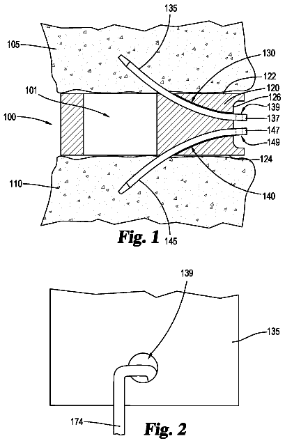
Intervertebral implant having mechanical securement
An intervertebral implant for implantation between an upper vertebral body and a lower vertebral body is disclosed.
US 9,730,854 B2 · Assignee: Beijing Ryzur Axiom Medical Investment Co., Ltd. · Inventors: Ren; Song
Sheet 1 of 9 from the published document. All sheets in the USPTO PDF
A system for dynamically adjusting treatment angle under tension to accommodate variations in spinal morphology during spinal decompression therapy is provided. It provides a tensioning device including a patient-positioning means, a tension-producing actuator, a positioning device, a patient interface device, a control system and a display. The control system with feedback on the resultant tension vector applied to patient spine operationally configured to allow for adjustment of either tension producing actuator position, patient position, or both while applying tension to the patient spine during non-therapeutic tension levels. The control system automatically adjusts tension producing actuator work levels such that the resultant tension vector magnitude remains ideally constant during adjustment of resultant tension vector angle, reducing the risk of eliciting paraspinal muscle contraction due to changes in resultant tension vector magnitude.
Therapists utilize spinal decompression therapy non-operative in vitro to treat various spinal ailments including herniated discs, degenerative disc disease, sciatica, posterior facet syndrome, and post surgical pain. Decompression therapy is a derivative of traditional traction-based therapy, whereby the spine is pulled by an outside force (such as by a therapist manually or by an automated process). The spine is typically held in a continuous state of tension during traditional traction-based therapy. Decompression therapy differs from traditional traction therapy in that tension is applied to the spine at a specific angle. Also, during decompression therapy, various tensile forces are applied or cycled throughout the treatment period such that paraspinal muscles are relaxed and fatigued, allowing for interdiscal separation. These functions provide for a smooth transition between diffe
8 of 9 drawing sheets so far from the published document, cropped to the drawing. Every sheet is in the USPTO PDF.
What the patent claimed, word for word. All of it is now free to use.
This application is a U.S. National Stage application filed under 35 U.S.C. §371 from International Application Ser. No. PCT/CN2012/086566, which was filed Dec. 13, 2012, and published as WO 2013/087001 on Jun. 20, 2013, and which claims priority to Chinese Application No. 201110415599.1, filed Dec. 13, 2011, which applications and publication are incorporated by reference as if reproduced herein and made a part hereof in their entirety, and the benefit of priority of each of which is claimed herein.
The present invention relates to a system that applies tension to a patient's spine to treat the spine related diseases. More specifically, the present invention relates to a positioning correction system that applies tension to a patient's spinal lesion area through a range of angles, and that can adjust the angle dynamically under tension without changing the intended tension, for the purpose of fine tuning treatment angle for each patient.
Therapists utilize spinal decompression therapy non-operative in vitro to treat various spinal ailments including herniated discs, degenerative disc disease, sciatica, posterior facet syndrome, and post surgical pain. Decompression therapy is a derivative of traditional traction-based therapy, whereby the spine is pulled by an outside force (such as by a therapist manually or by an automated process). The spine is typically held in a continuous state of tension during traditional traction-based therapy. Decompression therapy differs from traditional traction therapy in that tension is applied to the spine at a specific angle. Also, during decompression therapy, various tensile forces are applied or cycled throughout the treatment period such that paraspinal muscles are relaxed and fatigued, allowing for interdiscal separation. These functions provide for a smooth transition between different levels of tension. In either traditional traction or decompression therapy, spinal tension is typically maintained for periods of 30 minutes or longer.
As the spine is placed into a state of tension, the spinal vertebrae will occur morphology change, this requires the control system must have the dynamic positioning correction function. Meanwhile, the dynamic automatic positioning correction processing also allows the lesioned intervertebral disc time to heal in the non-loaded state. Additionally, herniated discs (nucleus pulposa) is produced in back to normal position via negative pressure created by the separation of the vertebrae, realized the intervertebral disc disease to accept reset. Meanwhile, This dynamic positioning correction function can also be aided to implement para-spinal muscles maximum relax according to the patient weight set nonlinear logarithmic minus pressure control system. Since the conscious human (patient) may voluntarily and/or subconsciously flex the spinal muscles in reaction to tensile forces. Either or both patient reactions degrade the effectiveness of spinal traction or spinal decompression therapy.
A common spinal decompression therapy utilizes a non-feedback-providing tension producing actuator (any type of electro-mechanical, pneumatic, magnetic, hydraulic, or chemical actuator) connected to a patient via a patient interface device. The patient lay supine upon a treatment bed, head distal to the applied tension source. An upper body patient harness secures the upper patient body to the distal end of the bed (that end of the bed furthest from the source of tensile force generation). A lower body harness secures about the waist, and serves as the point at which the tension strap is connected. Tension-producing actuator output is increased or decreased to produce resultant tension changes at the point where the strap is attached to the patient. A linear actuator (any type of electro-mechanical, pneumatic, magnetic, hydraulic, or chemical actuator) is utilized to pull the patient's whole spine. And spinal decompression treatment system is based on the weighing data system by weighing the patients, for patients to be automatic setting decompression treatment, through the imaging data combining with a narrative, healthcare provider will complete lesions of the initial position, the positioner raise and lower the point at which the tension strap pulls from (treatment positioner), relative to the place of attachment to the patient, thus adjusting the angle of applied tension. The system also includes a tension measuring device (e.g., a loadcell) that is connected inline with the tension-producing actuator and patient to communicate tension metrics to a tension-producing actuator controlling device (e.g. computer). Thus, the system operates as a controlled-feedback loop whereby a planned tension profile can be applied to the patient and the actual applied forces can be verified by the computer.
In the above example, the point at which the tension strap pulls from relative to the place of attachment to the patient is typically fixed during application of tension. As the direction of pull is neither parallel nor perpendicular to the patient's spine, and as the patient lay supine (in this example) with their head distal to the applied tension source, the applied tension can be modeled as two force vectors, one inline with the patient's spine and away from the head, and one perpendicular to the patient's spine. In the event that the patient lay prone, the direction of the horizontal component of the applied tension resultant would remain the same, however the direction of the vertical component of the applied tension resultant would be reversed.
One defining characteristic of spinal decompression is that tension is applied at an angle, and that specific angles (which are specific to each device's design) affect a specific positioning ability to allow healthcare providers to treat location specific injuries, such as herniated spinal discs. In effect, locating the site(s) of spinal elongation maximizes the therapeutic benefit per therapy session. Traction, whereby forces are applied mostly inline with the spine, does not attempt to maximize spinal discs at specific interdiscal locations and spinal elongation position column by the adjustment on the angle of tension in spinal.
Devices of the type described above provide general guidelines as to the relative interdiscal space(s) affected by various angles of applied tension. These angles are calculated in many ways; no standards exist for their calculation. Spinal decompression manufacturers calculate which interdiscal space(s) is affected by relating applied tension force vectors (specific to their device) to commonly available radiographical charts. These radiographical charts typically show the ‘average spine’ (based on studies of measurements taken over many patients) or the ‘ideal spine’ (based on best-fit mathematical modeling of the spine). Variations in patient's spines can mean that a treatment angle designed to align the L4 and L5 vertebra actually is insufficient to align said vertebra or overly much, brining inferior vertebra in-line with unintended superior vertebra.
The shape of the human spine varies from human to human. Lordosis, or an inward curve (towards the front of the patient body), and kyphosis, or an outward curve (towards the back of the patient body), exist throughout the spine, and serve to balance the spine and body. Generally, the spine exhibits a lordotic curve between the Thoracic (middle spine) and Lumbar (lower spine) regions, and a kyphotic curve between the Thoracic and Cervical (upper spine or neck) region. The points and degree of inflection and deflection vary across patient populations.
At present, Magnetic Resonance Imaging (MRI) is routinely indicated prior to spinal decompression therapy, whereby affected disc levels are identified. Once the MRI-described interdiscal space(s) is established, healthcare providers follow spinal decompression device manufacturer's recommendations as to appropriate applied tension treatment angles. The healthcare provider is able to judge, by physical examination of the patient, advanced patient imaging (MRI, CT, X-ray, etc.), spinal decompression device manufacturer's treatment angle design, and experience using spinal decompression devices the ‘most likely’ proper treatment angle for a particular patient. Once the patient is actually on the spinal decompression device, strapped in, the final level of scrutiny by the healthcare provider with regards to treatment angle occurs. The healthcare provider will visually observe the patient's posture, feel the patient's spine and or other related bodies, and/or query the patient to make a final determination as to the correct treatment angle for that particular patient.
At present, The spinal pressure relief devices are employed angle positioning technology, healthcare providers must do one of two things when adjusting treatment angle after initiating treatment. The first option, pausing treatment, adjust treatment angle, and restart treatment, but since the provider can't dynamic continuous real-time observation of the spine in the minus pressure condition of the patients with feedback in this case, thus even if to adjust, can not ensure the accurate angle, which makes it difficult to realize patients and the provider interactive communication, scanning, and ultimately positioning lesions in the purpose of the position. The second option, in the treatment process and under the action of tension, while the provider observes and adjusts the angle. But this practice, since human operation, will inevitably change dynamic system in the system, which leads to exceed expected tension setting range change. This adjustment, for the present not tension compensation of the closed loop feedback system (with tension compensation feedback closed-loop system can make the expected tension in a time constant), due to the sudden change of angle, will make the expected tension suddenly changes that lead to spinal side muscle strong contraction, thus affecting the treatment effect.
The present invention seeks to demonstrate a unique method for fine tuning treatment angle for each patient. The present invention proposes a system designed to allow the healthcare provider to adjust treatment angle without changing intended tension levels. The system proposed would be able to account for mechanical dynamics and mechanical advantages of the system, and be calibrated to anticipate the increases and decreases in resultant tension that would otherwise occur while changing treatment angle under tension.
The present invention relates to a tension producing actuator feedback and correction system. The system is fast enough to allow treatment angle change under tension without changing intended tension, the advantages of this design are numerous. While the patient is under an initial intended tension and treatment angle, the healthcare provider can observe via sight and touch, and additionally querying the patient, the interdiscal sites affected by the initial treatment angle at which the resultant tension is applied to the patient. Keeping the patient at the initial intended tension while changing treatment angle (without changing intended tension level) allows the healthcare provider to observe, via at least the same pathways, the transition in patient posture, without inciting paraspinal muscle contraction due to unintended tension level changes. Dynamically adjusting treatment angle under tension allows the healthcare provider to adjust, up or down, the treatment angle to accommodate increases and decreases in lordosis, as observed under tension. Dynamically adjusting treatment angle under tension also allows the healthcare provider to query the patient for comfort and or increases or decreases in perceived pain, incorporating a measure of biofeedback into the therapy.
In general, the patient is positioned supine on the treatment bed, their lower spine over a lordotic support. The lordotic support is used to locate the apex of lordosis, which is utilized as a universal metric for calculating treatment angle across average or ideal patient morphologies. Regardless of the design of treatment angles for a specific spinal decompression or traction device, the device does include treatment angle designations designed to affect specific interdiscal locations. While the inclusion of designer treatment angle designations for a spinal decompression or traction device is not required, it is likely present per the current technology.
Average or ideal radiographical spinal models typically include a mean segmental angle and at least the first or second standard deviation measurements. The segmental angle would be an angle of lordosis, in the case of the lumbar spine, between one or more vertebra. The segmental angles utilized would be those between the fifth lumbar vertebra and the first sacral vertebra or L5-S1, the fourth and the fifth lumbar vertebra or L4-L5, the third and the fourth lumbar vertebra or L3-L4, the second and the third lumbar vertebra or L2-L3, and the first and second lumbar vertebra or L1-L2.
The design of the spinal decompression device provides treatment angles which would align vertebra (spinal disc) and elongate their intervertebral spaces for an average or ideal spine. As described above, differences in the degree of lordosis between vertebral segments will range slightly above or below the average or ideal models.
If the spinal decompression device is designed to allow treatment angle change without changing intended tension, and that treatment angle change is bounded by one standard deviation of measured or calculated (depending on the data used in the design of the device), then the device is capable of accommodating the average or ideal spine and all those patients within one standard deviation of the average or ideal model, formed according to an embodiment of the present invention. The device's dynamic angle adjustment bounds may be extended to two or even three standard deviations of the average or ideal model, to accommodate even more patients. The device's dynamic angle adjustment bounds may incorporate the entire angle adjustment range of the device, allowing the healthcare provider to move up and down the entire lower spine.
By first utilizing angles described by spinal decompression device manufacturers as treating specific interdiscal locations and by then applying tension at that angle, the healthcare provider is able to initiate therapy in the general location of the interdiscal space(s) to be treated. If the healthcare provider is then capable of further adjusting the angle of applied tension during the application of said tension, and if the tension feedback and correction mechanism of the spinal decompression device is fast and accurate enough such that no noticeable increase or decrease in intended tension is incurred (thus minimizing conscious and subconscious paraspinal muscle contraction), the healthcare provider is then capable of fine tuning the treatment angle. The healthcare provider can observe real-time changes in the patient and the alignment of their spine, under tension. Paraspinal muscles may contract in response to stretching, and definitely will contract in an involuntary guarding response if sudden changes in tension occur. If the spinal decompression device's tension control feedback and correction loop is fast and accurate enough to allow for angle change and compensate for inevitable changes in mechanical advantage such that the paraspinal muscles are not incited to guard and contract, then the healthcare provider can in effect ‘scan’ the patient's spine in the vicinity of the interdiscal space(s) of interest. This process may be limited to an initial period of treatment. This process may also be limited to a range of angle adjustment, whereby the healthcare provider selects an initial treatment angle based on diagnostic evidence and device manufacturer design, and then fine tunes only to less than, only to greater than, or above and below the initial treatment angle by a certain amount (e.g., 0.5 degrees).
In summary, the present invention describes the device of which as being capable of adjusting the angle of applied tension without changing (significantly) the amount of intended tension, such that the healthcare provider can adjust the angle of tension during the application of tension without inciting conscious or subconscious paraspinal muscle contraction.
Additionally, the present invention may be utilized in conjunction with patient feedback to help locate the treatment angle that best addresses the patient's pain. Just as therapeutic massage addresses muscular tensions, whereupon the recipient of the massage knows instantly when the therapist addresses the correct site or source of pain, so may the patient undergoing spinal decompression therapy recognize when a spinal decompression device addresses the correct interdiscal site or source of pain. If the healthcare provider is then capable of further adjusting the angle of applied tension during the application of said tension, and if the tension feedback and correction mechanism of the spinal decompression device is fast and accurate enough such that no noticeable increase or decrease in intended tension is incurred, the healthcare provider is then capable of querying the patient real-time as to whether increasing or decreasing the angle of applied tension feels more or less appropriate. By scanning the spine and querying the patient as to what feels more appropriate, the healthcare provider has an additional input as to the correct location for spinal decompression to be maximized.
According to one respect of the present invention, providing a tensioning device, comprising: a patient-positioning means configured to high precisionly, repeatedly align a target region of a patient spine; a tension-producing actuator configured to place a patient spine in tension; a positioning device operationally configured to position tension producing actuator relative to target region of patient spine; a patient interface device operationally configured to interface tension producing actuator with patient spine; a control system with feedback on resultant tension vector applied to patient spine operationally configured to allow for adjustment of either tension producing actuator position, patient position, or both while applying tension to the patient spine during non-therapeutic tension levels; and a display operationally configured to provide data regarding resultant tension vector to the user or healthcare provider; wherein the control system automatically adjusts tension producing actuator work levels such that resultant tension vector magnitude remains ideally constant during adjustment of resultant tension vector angle, reducing risk of eliciting paraspinal muscle contraction due to changes in resultant tension vector magnitude.
The patient positioning means includes a patient bed, wherein a region of the patient bed is identified as the alignment-region over which a target region of the patient spine should be positioned. The patient bed includes physically removable portions of the bed body and a series of physical device related to the treatment attached thereof.
The tension producing actuator includes an electro-mechanical device which generates torque through rotation. The tension producing actuator includes a means of increasing or decreasing torque generated.
The positioning device includes a removable positioning means by which increases and decreases in the height of the tension producing actuator relative to the target region of the patient spine are accomplished.
The patient interface includes a strap connected to a patient harness, one end of the strap includes a connection to the rotation of the tension producing actuator, and a connection to a patient harness at its opposite end, the patient harness cradling a portion of the patient pelvis and the spine. The patient interface is operationally configured to translate the decompression tension generated by the torque generated by the tension producing actuator to the patient spine.
The control system allows for user or healthcare provider input and includes a means to set, generate, and keep ideally constant resultant tension vector magnitude during which either resultant tension vector angle or patient spine target region position relative on the device is adjusted by user or healthcare provider. The control system allows for user or healthcare provider to modify resultant tension vector angle while tension is applied to patient spine, the resultant tension vector magnitude kept ideally constant, while patient spine target region position relative to a location on the device is unchanged.
The control system allows for user or healthcare provider to modify patient spine target region position relative to a location on the device while tension is applied to patient spine, the resultant tension vector magnitude kept ideally constant, while tension producing actuator position relative to a location on the device is unchanged.
The control system allows for user or healthcare provider to set resultant tension vector angle and to modify patient spine target region position relative to a location on the device while tension is applied to patient spine, the resultant tension vector magnitude kept ideally constant, the control system automatically adjusting tension producing actuator position relative to a location on the device to maintain user set resultant tension vector angle.
The control system includes a display or means for communicating resultant tension vector angle and magnitude to the user or healthcare provider.
The control system allows for a user or healthcare provider to visually assess, physical palpitate, or verbally or otherwise receive feedback from the patient to modify patient position and to achieve concentration of resultant tension vector magnitude near a vertebral area of interest during applied ideally constant resultant tension vector magnitude.
The control system indicates the region of the spine where resultant tension is concentrated based on empirical calculation of said location relative to a spinal model and mathematical and medical assumptions.
The control system calculates region of the spine where resultant tension is concentrated based on ideal spine models arrived at through clinically cited spinal morphology studies.
The user or healthcare provider is able to visually assess, palpitate, and/or query patient to determine optimum pre-treatment treatment angle or resultant tension vector angle while reducing risk associated with eliciting a paraspinal muscle contraction due to changes in resultant tension vector magnitude.
FIG. 1 illustrates a side view of a spinal therapy system formed according to an embodiment of the present invention.
FIG. 2 illustrates the coccyx, sacrum, and lumbar spine, the lumbar spine being modeled about an ellipse, showing angles between adjacent vertebra.
FIG. 3 illustrates a side view of a spinal therapy system utilizing a lordotic support, specific patient positioning, and treatment angle structure based on FIG. 2 , formed according to an embodiment of the present invention.
FIGS. 4A and 4B illustrate two side views of a coccyx, sacrum, and lumbar spine before and after the application of tension at a specific angle designed to align the sacrum and lowest lumbar vertebra (S1 and L5 respectively) and to elongate that interdiscal space (L5-S1), formed according to an embodiment of the present invention.
FIGS. 5A and 5B illustrates two side views of a coccyx, sacrum, and lumbar spine. The upper view illustrates the lower spine after the application of tension at an angle designed to align the sacrum and lowest lumbar vertebra (S1 and L5 respectively) and to elongate that interdiscal space (L5-S1). The lower view illustrates the upper view after the application of tension at an additional specific angle designed to align the lowest lumbar vertebra with the fourth distal lumbar vertebra (L5 and L4 respectively), and to elongate the interdiscal spaces (L5-S1 and L4-L5), formed according to an embodiment of the present invention.
FIGS. 6A-6C illustrates three views of the coccyx, sacrum, and lumbar spine. The upper view represents the lower spine relaxed, before the application of tension at a specific angle. The second (middle) view represents the lower spine after the application of tension at an angle designed(θ.sub.T) (using average or ideal spine radiographical models) to align the first sacral and fifth lumbar vertebra. The second view illustrates the first sacral vertebra rotated overly much upwards beyond alignment with the fifth lumbar vertebra by an angle (θ.sub.diff). The second view shows how the fifth lumbar vertebra L5 is rotating towards an unintended alignment with the fourth lumbar vertebra L4. The third (lowest) view shows the first sacral vertebra rotated downward by a subtractional angle (θ.sub.diff), adjusted during tension by the healthcare provider, sufficient to bring the first sacral vertebra into proper alignment with the fifth lumbar vertebra for that patient segmental angle (θ.sub.1-θ.sub.0), formed according to an embodiment of the present invention.
FIGS. 7A-7C illustrate three views of the coccyx, sacrum, and lumbar spine. The upper view represents the lower spine relaxed, before the application of tension at a specific angle. The second (middle) view represents the lower spine after the application of tension at an angle designed (using average or ideal spine radiographical models) to align the first sacral and fifth lumbar vertebra. The second view illustrates the first sacral vertebra rotated insufficiently upwards towards alignment with the fifth lumbar vertebra by an angle (θ.sub.T) designed to align the vertebra. The third (lowest) view shows the first sacral vertebra rotated upward by an additional angle (θ.sub.diff), adjusted during tension by the healthcare provider, sufficient to bring the first sacral vertebra in proper alignment with the fifth lumbar vertebra, formed according to an embodiment of the present invention.
FIG. 8 illustrates a flowchart demonstrating an algorithm for adjusting treatment angle by a predetermined amount while not changing intended tension, formed according to an embodiment of the present invention.
FIG. 9 illustrates a spinal decompression treatment graph, showing intended tension, treatment angle, measured tension, and tension correction versus time, formed according to an embodiment of the present invention.
The foregoing summary, as well as the following detailed description of certain embodiments of the present invention, will be better understood when read in conjunction with the appended drawings. For the purpose of illustrating the invention, there is shown in the drawings, certain embodiments. It should be understood, however, that the present invention is not limited to the arrangements and instrumentalities shown in the attached drawings.
FIG. 1 illustrates a spinal therapy system 10 used to treat a patient 110 formed according to an embodiment of the present invention. The system 10 includes a microprocessor, control system, or computing device 190 having firmware and/or software that operates to utilize and control an actuator 170 . The computing device 190 is configured to interface with a user, such as by use of a monitor and keyboard setup. By way of example only, the actuator 170 may be electronically, hydraulically, pneumatically, or mechanically operated. The actuator 170 is connected to a patient 110 via a patient interface device 120 . By way of example, the actuator 170 may be operated through a system of gears or pulleys such that the tensile forces applied to the patient 110 by the patient interface device 120 are carefully controlled. This system 10 is used to perform decompression therapy on the patient 110 by applying cycles of tensile forces from the actuator 170 on the spine 108 of the patient 110 through the interface device 120 . Alternatively, the system 10 may be used to perform traction therapy without use of cycles of tensile forces.
The patient 110 is positioned supine on a mechanical apparatus 100 that may be a flat surface such as a bed or table. The bed 100 includes a head end 104 where the patient 110 lay his or her head and a base end 106 where the patient 110 lay his or her legs and feet. The bed 100 is positioned such that the patient 110 may be easily placed into alignment for treatment with the system 10 . Additionally, the bed 100 may employ arm supports or rails to position the patient 110 . The patient 110 wears a lower-body harness 118 that is connectable to the patient interface device 120 . This lower-body harness allows for connection to the patient interface device 120 at or near the base of the sacrum, or is designed to locate the origin of the resultant tension vector at or near the base of the sacrum. Alternatively, the patient may wear any other appropriate device that is configured to connect the patient 110 to the interface device 120 , provided the device position the origin or locate the origin of the resultant tension vector at or near the base of the sacrum. The patient 110 wears an upper-body harness 119 that is connectable to the head end 104 of the bed 100 . The upper-body harness 119 secures the upper body of the patient 110 to the bed 100 , and keeps the upper body of the patient 110 from moving towards or away from the tower 130 which houses the actuator 170 and interface positioning device 140 .
The healthcare provider positions the patient's 110 lumbar spine 108 over an adjustable lordotic support 112 . The adjustable lordotic support 112 is pneumatically inflated and deflated to accommodate various degrees of lumbar lordosis between patients 110 . The lordotic support 112 may be adjustable or fixed in shape, and may be adjustable by several methods, including pneumatic, electro-mechanical, hydraulic, chemical, etc. Specifically, the healthcare provider positions the apex of lordosis, the third lumbar vertebra (L3), over the center-top of the lordotic support 112 . Positioning the apex of lordosis over the center-top of the lordotic support 112 and anchoring the patient's 110 upper body to the head end 104 of the bed 100 forms a reliable and consistent endpoint for the horizontal line (opposite side) of the triangle which is used to calculate treatment angle.
The healthcare provider places a knee bolster 117 under the patient's 110 knees, reducing pressure on the patient's 110 lower spine 108 . The patient's 110 position on the bed 100 , supine with a bolster 117 under the knees, forms the basis for selection of radiographical measurements which take into account this position for use in designating treatment angles.
The lower-body harness 118 is connected to the actuator 170 by the patient interface device 120 . The harness 118 may be connected to the patient interface device 120 through a clip or buckle that may alternately be secured and removed. The interface device 120 is configured to deliver and align tensile forces generated by the actuator 170 through the harness 118 along the spine 108 of the patient 110 .
The interface device 120 may be a strap, belt, or cable that is positioned relative to the patient 110 via a patient interface positioning device 140 . The patient interface positioning device 140 may itself be moved to preferred positions by an vertical actuator 148 , which may be a linear actuator, or any other type of electro-mechanical, pneumatic, hydraulic, or chemical actuator. The vertical actuator 148 may contain a relative or absolute encoder, potentiometer, or optical distance sensor, for use in communicating the position of the patient interface positioning device 140 to an electronic communication hub 155 by way of arrow F. The patient interface device 120 , as it travels up and down via the patient interface positioning device 140 and vertical actuator 148 , may pass thru a slot 145 in the front of the tower 130 , which may utilize some form of flexible material to move with the patient interface device 120 and shield the inside of the tower 130 from outside interference.
The head end 104 and base end 106 bed 100 mattresses may be moved together horizontally towards and away from the tower 130 via a horizontal actuator 114 and clevis 116 , which may be a linear actuator or any of electro-mechanical, pneumatic, hydraulic, or chemical type. This would generally be done to accommodate patients 110 of various heights, such that those patient's 110 feet would not be uncomfortably near to or beyond the base end 106 of the bed 100 . The horizontal actuator 114 may contain a relative or absolute encoder, potentiometer, or optical distance sensor, for use in communicating the position of the lordotic support 112 and head end 104 mattress to either or both the computing device 190 and electronic communication hub 155 .
The base end 106 mattress of the bed 100 is designed to be locked into place with and travel horizontally with the head end 104 mattress of the bed 100 . It is also capable of unlocking from the head end 104 mattress of the bed 100 , and traveling a fixed distance away from the head end 104 mattress of the bed 100 along linear guides. This function serves to allow the spine 108 to elongate more easily under tension, as opposed to slipping and sliding down the base end 106 mattress of the bed 100 were it fixed to the head end 104 mattress. The base end 106 mattress and head end 104 mattress were joined entirety, this case would be less favorable for the spine free elongation with the decompression tension.
The system 10 further includes a tensile force feedback system 160 which engages the interface device 120 between the actuator 170 and the lower-body harness 118 . The feedback system 160 may include a loadcell or dynamometer 150 that is positioned inline with the actuator 170 and is configured for electronically providing feedback to the electronic communication hub 155 as indicated by arrow E.
The electronic communications hub 155 is designed to collect and relay various system 10 metrics to the computing device 190 as indicated by arrow A. This device may synchronize various system 10 measurement device information into a single data stream A designed to be best utilized by the computing device 190 .
The actuator 170 electronically communicates with, and is controlled directly by, an actuator controller 192 as shown by arrow B. By way of example only the actuator controller 192 is a servo-amplifier 192 . The actuator 170 may also be attached to, or connected inline with, an encoder 180 that is capable of communicating motor shaft position and other motor metrics with the servo-amplifier 192 . The servo-amplifier 192 may be capable of calculating any number of motor metrics, including work, position, distance, torque, and rate and electronically communicating those metrics to, and receiving them from, the computing device 190 as indicated by arrow C to the computing device 190 .
The computing device 190 may be configured to communicate with the servo-amplifier 192 , and the actuator 170 , to monitor and to correct as needed the resultant tensile force and motor metrics applied by the actuator 170 from the servo-amplifier 192 . The computing device 190 may also be configured for use with a user interface system (e.g., keyboard and monitor) which communicates and deciphers the user's commands to the computer 190 . This interface allows the user to structure treatment parameters. By way of example, all tension-producing and delivery apparatus are contained within a tower 130 located in a position relative to the patient 110 .
In operation, spinal treatment begins by positioning the patient 110 correctly onto the bed 100 . The patient's head is positioned at the head end 104 of the bed 100 , and the patient's feet are positioned at the base end 106 of the bed 100 . The patient 110 is outfitted with the lower body harness 118 such that the patient 110 is connected to the patient interface device 120 , and the lower body harness 118 is configured to apply tensile forces to the spine 108 of the patient 110 , the origin of the resultant tension vector located at or near the base of the sacrum. The patient is outfitted with an upper body harness 119 which is fixed into position at the head end 104 of the bed 100 . The healthcare provider positions the patient's 110 apex of lordosis over the center-top of the lordotic support 112 , adjusts the height of the support to match the curvature of the patient's lordosis there, and adjusts the upper-body harness 119 connection to the head end 104 of the bed 100 to make certain the upper body of the patient 110 is fixed into position on the head end 104 mattress. A bolster 117 is placed under the patient's 110 knees.
The operator of the decompression system 10 may use the patient interface system of the computer 190 to select the proper treatment parameters for the therapy. The operator may then select a tension treatment program for the patient 110 and instruct the computing device 190 to execute the selected treatment profile. The computing device 190 activates the servo-amplifier 192 and/or actuator 170 such that the actuator 170 rotates, for example in the direction of arrow D, to tighten the patient interface device 120 and thus apply tension to the patient's spine 108 through the lower body harness 118 . The computing device 190 adjusts the tensile output to follow the cycles of tensile forces defined in the treatment program entered by the user. The program may include low and high tension plateaus above, by way of example only, 125 pounds, and may also include any number of decompression therapy variations cyclically applying tension to the patient's spine 108 .
FIG. 2 illustrates the Lumbar Lordosis Elliptical Model 205 formed of radiographic measurements over many patients. Janik et all developed an idealized average subject anthropometric model of the lumbar lordosis from inferior of T12 to superior S1. The elliptical model 205 represents the idealized path of the posterior longitudinal ligament along the posterior aspect of the vertebral bodies 2 . This model 205 represents one method by which spinal decompression device designers may designate treatment angles formed according to an embodiment of the present invention. The ellipse 205 about which the spine 200 is modeled has minor axis B 210 passing through the inferior endplate 212 of T12 275 and a major axis A 215 perpendicular to the minor axis 210 Janik et all found the b/a ratio of 0.32 to be the best fit for the data presented.
The lower spine 200 pictured in FIG. 2 is composed of the first sacral vertebra 230 (S1), the fifth lumbar vertebra 225 (L5), the fourth lumbar vertebra 240 (L4), the third lumbar vertebra 250 (L3), the second lumbar vertebra 260 (L 2 ), the first lumbar vertebra 270 (L1), and the twelfth thoracic vertebra 275 (T12).
The tangent lines in FIG. 2 are drawn according to the Harrison Posterior Tangent (HPT) method. The HPT lines drawn along the posterior bodies of the bony vertebra are shown, the angle between adjacent tangent lines defining the segmental angle between vertebra per the elliptical model 205.
The segmental angle between L5 225 and S1 230 , or L5-S1, is determined by the angle between the tangent lines θ.sub.1 235 and θ.sub.0 220 .
The segmental angle between L4 240 and L5 225 , or L4-L5, is determined by the angle between the tangent lines θ.sub.2 245 and θ.sub.1 235 .
The description continues in the full USPTO document.
About 6,248 words. The USPTO PDF has it with every drawing.
Fees are due 3.5, 7.5 and 11.5 years after grant. This patent expired on August 15, 2025, so the fee marked "not paid" was the one that went unpaid.
SYSTEM FOR DYNAMICALLY ADJUSTING TREATMENT ANGLE UNDER TENSION TO ACCOMMODATE VARIATIONS IN SPINAL MORPHOLOGY
Filed Dec 2012 · published Dec 2014System for dynamically adjusting treatment angle under tension to accommodate variations in spinal morphology
Filed Dec 2012 · granted Aug 2017Earlier publications, parents and continuations. None of them can still be enforced, or this patent would not be listed.
Prior art cited by the examiner or applicant. Useful when you check your own idea for novelty.
Everything on this page comes from the documents linked above.