Background
1. Technical field
The present invention relates to a liquid ejection control device and the like which control a liquid ejection device ejecting a liquid in a pulsed state by using a piezoelectric element.
2. Related art
There is a known technology in which a liquid is ejected in a pulsed state and an excision target is excised. Ejection of a pulsed liquid is a jet flow of the liquid which is ejected from a nozzle in a pulsating manner and will be appropriately referred to as “a pulsed liquid jet” in this specification.
There are various purposes of the pulsed liquid jet. For example, JP-A-2005-152127 discloses a proposed technology in which the pulsed liquid jet is utilized for a surgical operation in the medical field. In this case, the excision target is a living tissue, and the liquid is a physiological salt solution.
As a mechanism which generates a pulsed liquid jet, there is a known mechanism in which a piezoelectric element is used. In the mechanism, the piezoelectric element generates an instantaneous pressure in an operation fluid (a fluid) so as to cause a liquid to be ejected in a pulsed state by adding a drive voltage in a pulse wave shape to the piezoelectric element. Accordingly, when varying the strength of the pulsed liquid jet, the drive voltage applied to the piezoelectric element is controlled. Therefore, it is possible to consider a specification in which the strength of the pulsed liquid jet becomes variable by instructing a characteristic value of a drive voltage applied to the piezoelectric element, for example, the amplitude of a drive voltage waveform (which is a voltage amplitude and can also be referred to as the magnitude of a drive voltage) through an operation unit such as an operation dial or an operation button.
However, it is found that even though the characteristic value of the drive voltage to be instructed through the operation unit is changed, there may be a case where excisional circumstances such as the depth of excision and the volume of excision of the excision target cannot be changed as intended by a user. Detailed description will be given below. However, for example, it is found that even though a user changes the voltage amplitude twice, four times, ½, or ¼, the depth of excision and the volume of excision do not necessarily change in the same manner. When the pulsed liquid jet is used for the purpose of a surgical operation, it is not possible for an operator to obtain an operational effect in accordance with the feeling of the operation, thereby causing the possibility of a problem.
Meanwhile, when a cycle of ejecting a pulsed liquid jet is caused to be variable, the depth of excision and the volume of excision per unit time can be increased and reduced so that the velocity of excising the excision target becomes adjustable. However, the strength and the like of the pulsed liquid jet for one pulse can be changed based on the fact that when the cycle of ejection is changed, the shape of the drive voltage waveform changes. Therefore, there may be a case where the excision speed proportional to the frequency of ejection as intended by a user cannot be obtained even though the depth of excision and the volume of excision caused by the pulsed liquid jet for one pulse are changed before and after the cycle of ejection is changed, and the cycle of ejection is shortened, that is, the frequency of ejection is raised.
In addition, for example, in a case of the purpose of a surgical operation, a plurality types of liquid ejection devices in each of which an ejection tube portion where a liquid passes through has the shape, the length, the tube diameter, the material, the diameter of a nozzle, or the like different from each other are classified in accordance with the circumstances of a surgical operation, a resection site, or the like. Therefore, the depth of excision and the volume of excision caused by the pulsed liquid jet for one pulse can be changed in accordance with the type of the ejection tube portion of the liquid ejection device in use.
Summary
An advantage of some aspects of the invention is to propose a technique in which the strength of a pulsed liquid jet can be set so as to meet the intention of a user and the user-friendliness thereof is improved.
A first aspect of the invention is directed to a liquid ejection control device which applies a given drive voltage waveform to a piezoelectric element and controls ejection of a pulsed liquid jet from a liquid ejection device which ejects a liquid in a pulsed state by using the piezoelectric element. The liquid ejection device has an ejection tube section in which an ejection port of the liquid is formed and which is configured to be attachable/detachable with respect to a main body section including the piezoelectric element. The liquid ejection control device includes a type discrimination unit that discriminates an ejection tube section type of the ejection tube section; a correspondence relationship acquisition unit that acquires a fitted correspondence relationship which fits the discriminated ejection tube section type from correspondence relationships that are set for each of the ejection tube section types while the correspondence relationship is based on a first instruction value related to momentum of the pulsed liquid jet, a second instruction value related to the number of times of ejection of the pulsed liquid jet per unit time, and an index value related to a voltage amplitude of the drive voltage waveform and rising of the drive voltage waveform; a first operation unit that inputs the first instruction value; a second operation unit that inputs the second instruction value; and a voltage amplitude setting unit that sets the voltage amplitude of the drive voltage waveform so as to cause the momentum to meet the first instruction value with reference to the fitted correspondence relationship based on the index value and the second instruction value.
As another aspect of the invention, the invention can be configured as a control method of applying a given drive voltage waveform to a piezoelectric element and controlling ejection of a pulsed liquid jet from a liquid ejection device which ejects a liquid in a pulsed state by using the piezoelectric element. The liquid ejection device has an ejection tube section in which an ejection port of the liquid is formed and which is configured to be attachable/detachable with respect to a main body section including the piezoelectric element. The control method includes discriminating an ejection tube section type of the ejection tube section; acquiring a fitted correspondence relationship which fits the discriminated ejection tube section type from correspondence relationships that are set for each of the ejection tube section types while the correspondence relationship is based on a first instruction value related to momentum of the pulsed liquid jet, a second instruction value related to the number of times of ejection of the pulsed liquid jet per unit time, and an index value related to voltage amplitude of the drive voltage waveform and rising of the drive voltage waveform; inputting the first instruction value; inputting the second instruction value; and setting the voltage amplitude of the drive voltage waveform so as to cause the momentum to meet the first instruction value with reference to the fitted correspondence relationship based on the index value and the second instruction value.
As described below, the depth of excision and the volume of excision performed by the pulsed liquid jet are highly related with the momentum of the pulsed liquid jet. Meanwhile, the relationship of the depth of excision and the volume of excision with the momentum may vary in accordance with the type of the ejection tube portion of the liquid ejection device. According to the first aspect and the like of the invention, the ejection tube section type of the ejection tube section mounted in the main body section is discriminated, and a fitted correspondence relationship which is set regarding the ejection tube section type is acquired. When the first instruction value related to the momentum of the pulsed liquid jet and the second instruction value related to the number of times of ejection of the pulsed liquid jet per unit time are input, the voltage amplitude of the drive voltage waveform is set so as to cause the momentum to meet the first instruction value in accordance with the fitted correspondence relationship based on the index value of the drive voltage waveform and the second instruction value. Accordingly, even though the type of the ejection tube section varies, it is possible to realize the depth of excision and the volume of excision answering the intention of a user and feeling of the operation by directly instructing the momentum of the pulsed liquid jet. Thus, the user-friendliness thereof can be improved.
Since the number of times of ejection of the pulsed liquid jet per unit time can be instructed, it is possible to increase and reduce the number of times of ejection while the first instruction value is maintained, for example. Therefore, it is possible to adjust an excision speed without changing the depth of excision and the volume of excision caused by the pulsed liquid jet for one pulse before and after the number of times of ejection is changed. Thus, an improvement of the user-friendliness thereof can be achieved.
A second aspect of the invention is directed to the liquid ejection control device according to the first aspect of the invention, in which the ejection tube section has a first retainer which retains type information of the ejection tube section, and the type discrimination unit acquires the type information from a read-out result of a first reader reading out retained information from the first retainer and may discriminate the ejection tube section type.
According to the second aspect of the invention, it is possible to discriminate the ejection tube section type of the ejection tube section mounted in the main body section by acquiring the type information of the ejection tube section from the first retainer which is included in the ejection tube section.
A third aspect of the invention is directed to the liquid ejection control device according to the first aspect of the invention, in which the type discrimination unit acquires at least any one of shape information and weight information of the ejection tube section and discriminates the ejection tube section type.
According to the third aspect of the invention, it is possible to discriminate the ejection tube section type of the ejection tube section mounted in the main body section by acquiring the shape information or the weight information of the ejection tube section.
A fourth aspect of the invention is directed to the liquid ejection control device according to any of the first to third aspects of the invention, in which the ejection tube section has a second retainer which retains the fitted correspondence relationship fitting the ejection tube section type of the ejection tube section, and the correspondence relationship acquisition unit acquires the fitted correspondence relationship from a read-out result of a second reader reading out retained information from the second retainer.
According to the fourth aspect of the invention, it is possible to acquire the fitted correspondence relationship fitting the ejection tube section type of the ejection tube section mounted in the main body section from the second retainer which is included in the ejection tube section.
A fifth aspect of the invention is directed to the liquid ejection control device according to any of the first to fourth aspects of the invention, which further includes a third operation unit that inputs a third instruction value related to the index value.
According to the fifth aspects of the invention, it is possible to input the third instruction value related to the index value of the drive voltage waveform.
A sixth aspect of the invention is directed to the liquid ejection control device according to any of the first to fifth aspects of the invention, which further includes a falling shape setting unit that variably sets a falling shape of the drive voltage waveform in accordance with the second instruction value.
According to the sixth aspect of the invention, it is possible to control repetitive ejection of the pulsed liquid jet by variably setting the falling shape of the drive voltage waveform so as to cause the number of times of ejection of the pulsed liquid jet per unit time to meet the second instruction value while a predetermined or desired rising shape of the drive voltage waveform is maintained.
A seventh aspect of the invention is directed to the liquid ejection control device according to any of the first to sixth aspects of the invention, which further includes a display control unit that performs controlling to display at least one of the first instruction value and the second instruction value.
According to the seventh aspect of the invention, it is possible to display at least one of the first instruction value related to the momentum of the pulsed liquid jet and the second instruction value related to the number of times of ejection of the pulsed liquid jet per unit time. Accordingly, it is possible to visually check the current momentum of the pulsed liquid jet instructed by a user, the index indicating the number of times of ejection per unit time, and the like. Therefore, the user-friendliness thereof can be further improved.
An eighth aspect of the invention is directed to the liquid ejection control device according to any of the first to seventh aspects of the invention, in which the liquid ejection device having momentum of the pulsed liquid jet within a range from 2 [nano-newton seconds (nNs)] to 2 [milli-newton seconds (mNs)] or having the kinetic energy within a range from 2 [nano-joules (nJ)] to 200 [milli-joules (mJ)] is controlled.
According to the eighth aspect of the invention, it is possible to control the liquid ejection device having the momentum of the pulsed liquid jet within the range from 2 [nNs] to 2 [mNs] or having the kinetic energy within a range from 2 [nJ] to 200 [mJ]. Accordingly, for example, it is suitable for excising soft materials such as living tissues, foods, a gel material, and resin materials such as rubber and plastic.
A ninth aspect of the invention is directed to the liquid ejection control device according to any of the first to eighth aspects of the invention, in which the liquid ejection device which excises a living tissue by using the pulsed liquid jet is controlled.
According to the ninth aspect of the invention, it is possible to control the strength of the pulsed liquid jet which is suitable for the purpose of a surgical operation, for example.
A tenth aspect of the invention is directed to a liquid ejection system including the liquid ejection control device according to any of the first to ninth aspects of the invention, a liquid ejection device, and a liquid delivery pump device.
According to the tenth aspect of the invention, it is possible to realize the liquid ejection system which exhibits the operational effects of the above-described aspects of the invention.
Brief description of the drawings
The invention will be described with reference to the accompanying drawings, wherein like numbers reference like elements.
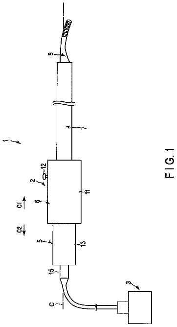
FIG. 1 is a diagram illustrating an example of the overall configuration of a liquid ejection system.
FIG. 2 is a diagram illustrating the internal structure of a liquid ejection device.
FIGS. 3A and 3B are diagrams illustrating a drive voltage waveform of a piezoelectric element in one cycle and a flow velocity waveform of a liquid at a liquid ejection opening.
FIGS. 4A to 4C are diagrams illustrating a mass flux, a momentum flux, and an energy flux.
FIGS. 5A to 5C are diagrams illustrating flow velocity waveforms of a main jet used in simulations of excisional circumstances of an excision target.
FIGS. 6A to 6F are diagrams illustrating simulation results (depth of excision).
FIGS. 7A to 7F are diagrams illustrating simulation results (volume of excision).
FIGS. 8A and 8B are diagrams illustrating simulation results of flow velocity waveforms of the main jet when drive voltage waveforms respectively having rising frequencies different from each other are applied.
FIGS. 9A and 9B are diagrams illustrating simulation results of flow velocity waveforms of the main jet when drive voltage waveforms respectively having voltage amplitudes different from each other are applied.
FIGS. 10A and 10B are diagrams illustrating simulation results of flow velocity waveforms of the main jet when drive voltage waveforms respectively having repetitive frequencies different from each other are applied.
FIG. 11 is a diagram illustrating a correspondence relationship among momentum, the rising frequency, and the voltage amplitude at a predetermined repetitive frequency.
FIG. 12 is a diagram illustrating an operation panel of a liquid ejection control device in Exemplary Embodiment 1.
FIG. 13 is a block diagram illustrating an example of a functional configuration of the liquid ejection control device in Exemplary Embodiment 1.
FIG. 14 is a diagram illustrating an example of a data configuration of an momentum conversion table in Exemplary Embodiment 1.
FIG. 15 is a diagram illustrating an example of a data configuration of an ejection tube section discrimination table.
FIG. 16 is a flow chart illustrating a flow of processing performed by a control unit at the time of ejection of a pulsed liquid jet in Exemplary Embodiment 1.
FIG. 17 is a diagram illustrating an operation panel of a liquid ejection control device in Exemplary Embodiment 2.
FIG. 18 is a block diagram illustrating an example of a functional configuration of the liquid ejection control device in Exemplary Embodiment 2.
FIG. 19 is a diagram illustrating an example of a data configuration of an momentum conversion table in Exemplary Embodiment 2.
FIG. 20 is a flow chart illustrating a flow of processing performed by a control unit at the time of ejection of a pulsed liquid jet in Exemplary Embodiment 2.
FIG. 21 is a diagram illustrating an example of a packing bag in which an ejection tube section is contained at the time of shipment.
Description of exemplary embodiments
Hereinafter, an embodiment of a liquid ejection control device, a liquid ejection system, and a control method according to the invention will be described. The invention is not limited by the embodiment described below, and a form to which the invention can be applied is not also limited by the below-referenced embodiment. In the disclosed drawings, the same reference numerals and signs are applied to the same portions.
Overall Configuration
FIG. 1 is a diagram illustrating an example of the overall configuration of a liquid ejection system 1 in the embodiment. The liquid ejection system 1 is used for the purpose of processing a soft material, for example, a surgical operation while having living tissues as an excision target, processing of foods while having foods as an excision target, processing of gel materials, and excision of resin materials such as rubber and plastic. The liquid ejection system 1 ejects a pulsed liquid jet of which the momentum ranges from 2 [nano-newton seconds (nNs)] to 2 [milli-newton seconds (mNS)] or the kinetic energy ranges from 2 [nano-joules (nJ)] to 200 [milli-joules (mJ)], thereby excising the excision target. Hereinafter, a case where incision, resection, or fragmentation of a lesion site (living tissues) (collectively referred to as “excision”) is carried out will be exemplified, while the liquid ejection system 1 is used for the purpose of a surgical operation. Description will be given on the assumption that momentum flux and momentum in the embodiment indicate scalar quantity, that is, magnitude in which only the component of the pulsed liquid jet in the ejection direction is considered.
As illustrated in FIG. 1 , the liquid ejection system 1 includes a container 10 which contains a liquid, a liquid delivery pump device 20 , a liquid ejection device 30 which ejects a liquid in a pulsed state toward an excision target (living tissues in the embodiment), and a liquid ejection control device 60 .
As operation units, the liquid ejection control device 60 includes an operation panel 70 for inputting various types of operations such as increasing/decreasing operations of momentum during a surgical operation, and an ejection pedal 81 for switching between a start and a stop of ejecting a pulsed liquid jet by being stepped on by an operator. Moreover, the liquid ejection control device 60 appropriately includes a reader/writer 82 which realizes reading and writing of data in a memory card 821 , a communication device 83 for communicating with an external server apparatus 100 , an image capturing device 84 , a code reader 85 , and a gravimeter 86 .
The container 10 contains liquid such as water, a physiological salt solution, and a liquid medicine. The liquid delivery pump device 20 supplies the liquid contained in the container 10 to the liquid ejection device 30 via connection tubes 91 and 93 at predetermined pressure or a predetermined flow rate at all times.
The liquid ejection device 30 includes a main body section 40 in which a piezoelectric element 43 and the like are provided inside a main body case 41 (refer to FIG. 2 ), and an ejection tube section 50 in which a pipe-like ejection tube 53 is erected on a base 51 . The ejection tube section 50 is configured to be attachable/detachable with respect to the main body section 40 . The liquid ejection device 30 is a portion to be held and operated by an operator in one's hand (a handpiece) during a surgical operation. The liquid ejection device 30 generates a pulse flow by applying pulsation to a liquid supplied from the liquid delivery pump device 20 and eventually ejects the generated pulse flow as a pulsed liquid jet from a liquid ejection opening 551 (refer to FIG. 2 ) which is provided in a nozzle 55 , through the ejection tube 53 .
Here, as the handpiece for a surgical operation, the handpiece of which the shape of an ejection tube portion, the length, the tube diameter, the material, and the diameter of the nozzle are different from each other is prepared, and a handpiece which is suitable for the circumstances of the surgical operation, a resection site, and the like is selectively used at the time of a surgical operation. As the type of the ejection tube portion, for example, a stainless steel-made ejection tube having a length of 15 [cm], 30 [cm], or 50 [cm], or a flexible PEEK tube having a length of 1 [m], 1.5 [m], or 2 [m] can be exemplified. Regarding the shape of the ejection tube portion as well, various types of shape such as a straight line-shaped ejection tube and a bent shaped ejection tube can be exemplified. In the embodiment, the handpiece is configured to replace only the ejection tube portion with another ejection tube which is suitable for the circumstances and the like of a surgical operation by causing the ejection tube section 50 including the ejection tube 53 to be attachable/detachable with respect to the main body section 40 which includes the piezoelectric element 43 and the like while the piezoelectric element 43 for generating the pulse flow is shared. In more detail, an ejection tube section 50 is selected from various types of ejection tube sections 50 in which the configurations of the bases 51 are the same as each other and ejection tubes having the lengths, materials, and the like different from each other are erected as the ejection tube 53 , in accordance with the circumstances of a surgical operation. The selected ejection tube section 50 is mounted in the main body section 40 , thereby being used.
The pulse flow denotes a pulsating flow of a liquid in a state where the flow velocity or pressure of the liquid changes in a temporally significant and rapid manner. Similarly, ejection of a liquid in a pulsed state denotes pulsating ejection of a liquid in a state where the flow velocity of the liquid passing through a nozzle changes in a temporally significant manner. The embodiment exemplifies a case where a pulsed liquid jet is ejected by applying cyclic pulsation to a steady flow. However, the invention can be similarly applied to ejection of a pulsed liquid jet sporadically and intermittently performed in a state where ejection and non-ejection of a liquid are repeated.
FIG. 2 is a diagram illustrating an overview of a cross-section obtained by cutting the liquid ejection device 30 along the direction of ejecting a liquid. FIG. 2 illustrates a fitting state of the main body case 41 and the base 51 . The scales of the lengths and the widths of the members and portions illustrated in FIG. 2 are different from the actual scales for convenience of illustration.
The main body case 41 of the main body section 40 has a box shape of which one end is open. The piezoelectric element 43 and a diaphragm 45 for changing the volume of a pressure chamber 57 are configured to be arranged in a tubular inner space thereof. Meanwhile, on a side opposite to the side where the ejection tube 53 is erected, the base 51 of the ejection tube section 50 has a recession 511 forming the pressure chamber 57 . When the ejection tube section 50 is mounted in the main body section 40 in the liquid ejection device 30 , the recession 511 of the base 51 fits the opening end of the main body case 41 , and the inside therebetween is sealed by a lock mechanism or the like which causes both to engage with each other. An attachment/detachment unit for the main body section 40 and the ejection tube section 50 can be appropriately selected.
The diaphragm 45 is a thin disk-shaped sheet metal, and an outer circumferential portion thereof is interposed between the main body case 41 and the base 51 so as to be fixed when being mounted in the ejection tube section 50 . The piezoelectric element 43 is a lamination-type piezoelectric element, for example. One end is fixed to the diaphragm 45 between the diaphragm 45 and a bottom plate 411 of the main body case 41 , and the other end is fixed to the bottom plate 411 .
The pressure chamber 57 is a space which is surrounded by the diaphragm 45 and the recession 511 of the base 51 . An inlet channel 513 and an outlet channel 515 which individually communicate with the pressure chamber 57 are formed on the base 51 . The inner diameter of the outlet channel 515 is formed to be greater than the inner diameter of the inlet channel 513 . The inlet channel 513 is connected to a connection tube 93 and introduces a liquid supplied from the liquid delivery pump device 20 , to the pressure chamber 57 . One end of the ejection tube 53 is connected to the outlet channel 515 and introduces a liquid flowing inside the pressure chamber 57 , to the ejection tube 53 . The nozzle 55 which includes the liquid ejection opening 551 having the inner diameter smaller than the inner diameter of the ejection tube 53 is inserted into the ejection tube 53 and is attached to the other end (the distal end) thereof.
The ejection tube section 50 is provided with an ejection tube side retainer 59 which is a first retainer retaining an ejection tube section ID as type information thereof allocated for an ejection tube section type of the ejection tube section 50 . The main body section 40 is provided with a reader 47 which is a first reader for reading the ejection tube section ID from the ejection tube side retainer 59 . The ejection tube side retainer 59 and the reader 47 are arranged respectively at appropriate places of the ejection tube section 50 and the main body section 40 so as to have a positional relationship in which the ejection tube side retainer 59 can be read by the reader 47 in the fitting state of the main body case 41 and the base 51 . The ejection tube side retainer 59 is configured to be an integrated circuit (IC) tag which stores the ejection tube section ID, for example. Meanwhile, the reader 47 is configured to be an IC tag reader reading out the ejection tube section ID from the IC tag and outputs the read out ejection tube section ID to the liquid ejection control device 60 . Otherwise, the ejection tube side retainer 59 may be configured to be formed by using an information code which is obtained by encoding the ejection tube section ID (for example, may be a bar code, and may also be a two-dimensional code). In this case, the reader 47 is configured to be a code reader which reads out the information code, thereby analyzing the read out information code and outputting the ejection tube section ID to the liquid ejection control device 60 . The main body section 40 includes a main body side retainer 49 which is connected to the liquid ejection control device 60 through wire.
The ejection tube side retainer 59 and the reader 47 are configured to be arranged respectively in the ejection tube section 50 and the main body section 40 so as to have the positional relationship in which the reader 47 can perform reading in the fitting state of the main body case 41 and the base 51 . However, as long as information stored in the IC tag can be read out, the arrangement may have a differently arranged positional relationship. For example, the arrangement may have a positional relationship in which reading can be performed at an adjacent position or in a contact state before being in the fitting state.
In the liquid ejection system 1 having the above-described configuration, a liquid contained in the container 10 is supplied to the liquid ejection device 30 by the liquid delivery pump device 20 via the connection tube 93 at predetermined pressure or a predetermined flow rate while being under the control of the liquid ejection control device 60 . Meanwhile, when a drive signal is applied to the piezoelectric element 43 while being under the control of the liquid ejection control device 60 , the piezoelectric element 43 expands and contracts (arrow A in FIG. 2 ). Since the drive signal applied to the piezoelectric element 43 is repetitively applied at a predetermined repetitive frequency (for example, several ten [Hz] to several hundred [Hz]), expansion and contraction of the piezoelectric element 43 are repeated for each cycle. Accordingly, pulsation is applied to a liquid in a steady flow flowing inside the pressure chamber 57 , and a pulsed liquid jet is repetitively ejected from the liquid ejection opening 551 .
FIG. 3A is a diagram illustrating an example of a drive voltage waveform L 11 of the drive signal in one cycle applied to the piezoelectric element 43 . FIG. 3A also illustrates a flow velocity waveform L 13 of a liquid in the liquid ejection opening 551 . FIG. 3B is a diagram of a flow velocity waveform (the main peak portion) S 1 which is the highest peak extracted from the peaks of the flow velocity waveform L 13 illustrated in FIG. 3A .
The reference sign Tp illustrated in FIG. 3A is a repetitive cycle (a time for one cycle of the drive voltage waveform), and the reciprocal thereof is the above-described repetitive frequency. The repetitive cycle Tp ranges approximately from 1 [millisecond (ms)] to 100 [ms], and a time Tpr necessary for the drive voltage waveform to rise to the maximum voltage (a rising time) ranges approximately from 10 [microsecond (μs)] to 1000 [μs]. The repetitive cycle Tp is set to be a time longer than the rising time Tpr. When the reciprocal of the rising time Tpr is set to be the rising frequency, the repetitive frequency is set to be a frequency lower than the rising frequency. Both the rising frequency and the rising time are one of index values (rising index values) related to rising of the drive voltage.
For example, when the piezoelectric element 43 is set to expand as a positive voltage is applied, the piezoelectric element 43 rapidly expands at the rising time Tpr, and the diaphragm 45 is pressed by the piezoelectric element 43 and is thereby bent toward the pressure chamber 57 side. As the diaphragm 45 is bent toward the pressure chamber 57 side, the volume of the pressure chamber 57 is reduced, and a liquid inside the pressure chamber 57 is extruded out of the pressure chamber 57 . Here, since the inner diameter of the outlet channel 515 is greater than the inner diameter of the inlet channel 513 , the fluid inertance and the fluid resistance of the outlet channel 515 are smaller than the fluid resistance of the inlet channel 513 . Therefore, as the piezoelectric element 43 rapidly expands, the most portion of the liquid extruded out of the pressure chamber 57 passes through the outlet channel 515 and is introduced to the ejection tube 53 . Then, the extruded liquid becomes pulsed droplets, that is, a pulsed liquid jet by the liquid ejection opening 551 having the diameter smaller than the diameter of the ejection tube 53 , thereby being subjected to high velocity ejection.
After having risen to the maximum voltage, the drive voltage gradually drops. In this case, the piezoelectric element 43 contracts while taking time longer than the rising time Tpr, and the diaphragm 45 is pulled by the piezoelectric element 43 so as to be bent toward the bottom plate 411 side. As the diaphragm 45 is bent toward the bottom plate 411 side, the volume of the pressure chamber 57 is increased, and a liquid is introduced to the inside of the pressure chamber 57 from the inlet channel 513 .
Since the liquid delivery pump device 20 supplies a liquid to the liquid ejection device 30 at predetermined pressure or a predetermined flow rate, if the piezoelectric element 43 does not perform the expansion/contraction operation, the liquid (the steady flow) flowing in the pressure chamber 57 is introduced to the ejection tube 53 via the outlet channel 515 and is thereby ejected from the liquid ejection opening 551 . Since the ejection is a liquid current at a steady velocity and a low velocity, the ejection can be referred to as a steady flow.
Principle
An essential factor as a value characterizing the pulsed liquid jet is the flow velocity waveform L 13 of a jet for one pulse in the liquid ejection opening 551 illustrated in FIG. 3A together with the drive voltage waveform L 11 . Above all, a noteworthy factor is the main peak portion (the jet of a leading wave: S 1 in FIG. 3A ) of the maximum flow velocity generated immediately after the rising of the drive voltage which is extracted and illustrated in FIG. 3B . The remaining low peaks are generated due to jets which are incidentally ejected as wave of pressure fluctuation generated inside the pressure chamber 57 at the time of expansion of the piezoelectric element 43 reflectively reciprocate inside the ejection tube 53 . However, the factor which determines the excisional circumstances such as the depth of excision and the volume of excision of the excision target is the jet of the leading wave (hereinafter, referred to as “the main jet”) of which the flow velocity is the greatest.
Incidentally, when it is intended to change the strength of the pulsed liquid jet so as to change the depth of excision and the volume of excision of the excision target, the drive voltage waveform of the piezoelectric element 43 is controlled. Regarding controlling of the drive voltage waveform, a method performed by an operator instructing the rising frequency of the drive voltage waveform or the amplitude (the voltage amplitude) of the drive voltage waveform as the voltage characteristic value thereof can be considered. For example, a method performed by an operator instructing the rising frequency (may be the rising time Tpr) in a state where the voltage amplitude is fixed or instructing the voltage amplitude in a state where the rising frequency is fixed can be considered. It is because the voltage amplitude and the rising frequency (the rising time Tpr) thereof greatly affect the flow velocity waveform of the main jet. While the drive voltage has risen to the maximum voltage and gradually drops thereafter, the drive voltage does not particularly affect the flow velocity waveform of the main jet. Therefore, it is considered that the depth of excision becomes deep and the volume of excision becomes significant so as to be proportional thereto by raising the rising frequency or increasing the voltage amplitude.
However, there is a case where the depth of excision and the volume of excision of the excision target actually achieved do not necessarily change so as to answer the increase/decrease of the voltage characteristic value. Therefore, it has become clear that there is a case where the user-friendliness thereof is deteriorated. For example, there may be a case where the depth of excision and the volume of excision do not increase as intended even when an operator increases the voltage amplitude twice, or the depth of excision and the volume of excision do not decrease as expected even when the voltage amplitude is decreased to ½. Therefore, there can be an occurrence of a situation where the depth of excision and the volume of excision desired by an operator are not achieved. This is a problem that a surgical operation time is unavoidably elongated.
There is a case where the excision speed is intended to be adjusted separately from the strength of the pulsed liquid jet. As a specification thereof, a method performed by an operator instructing the repetitive frequency of the drive voltage waveform can be considered. For example, a raised repetitive frequency denotes that the number of times of ejection of the pulsed liquid jet per unit time is increased, leading to a change in the depth of excision and the volume of excision achieved at the final stage.
However, even though the repetitive frequency is changed based on the fact that the drive voltage waveform changes when the repetitive frequency is changed, the depth of excision and the volume of excision per unit time do not change in proportion thereto, thereby leading to a case where the user-friendliness is unfavorable for an operator. Specifically, for example, it is possible to consider a method of changing the repetitive frequency by simply increasing and reducing the drive voltage waveform in its entirety in the time axis direction. However, the method causes a fluctuation of the rising frequency which significantly affects the flow velocity waveform of the main jet so that the strength of the pulsed liquid jet changes as described above. Therefore, it is not possible to obtain the intended excision speed which is proportion to the repetitive frequency.
Therefore, while paying attention to the flow velocity waveform of the main jet, correlationship of the depth of excision and the volume of excision with some parameters which are determined by the flow velocity waveform of the main jet is studied. It is because when a parameter having the high correlationship with respect to the depth of excision and the volume of excision is found, it is possible to control the piezoelectric element 43 at the optimum drive voltage waveform in order to achieve the depth of excision and the volume of excision in accordance with the feeling of an operation for an operator.
The description continues in the full USPTO document.
 Lapsed, fee not paid7 drawings