Background of the invention
1. Field of the invention
The present invention relates to an ultrasonic probe to perform cutting of, for example, a hard bone tissue and a cartilage tissue by ultrasonic vibration.
2. Description of the related art
In Jpn. Pat. Appln. KOKAI Publication No. 2005-152098, there is disclosed an ultrasonic treatment device including an ultrasonic probe (an ultrasonic horn). In this ultrasonic treatment device, an ultrasonic vibration generated in a vibration generating section (an ultrasonic vibration mechanism) is transmitted from a proximal side toward a distal side in the ultrasonic probe. In a distal portion of the ultrasonic probe, a scalpel portion is formed as a treating surface. In the scalpel portion, an outer surface of the ultrasonic probe is formed in an uneven state. The ultrasonic vibration is transmitted to the scalpel portion in a state where the scalpel portion is in contact with a treated target, whereby the treated target (e.g., a bone or another hard tissue) is cut.
Brief summary of the invention
According to one aspect of the invention, an ultrasonic probe used in a shoulder joint, the ultrasonic probe being configured to transmit an ultrasonic vibration so as to treat the shoulder joint by use of the ultrasonic vibration, the ultrasonic probe including: a probe main body section which is extended along a longitudinal axis, and which is configured to transmit the ultrasonic vibration from a proximal side toward a distal side; a curved extending section which is provided on the distal side with respect to the probe main body section, and which is extended in a state of curving relative to the probe main body section toward a first intersecting direction side in a case where a certain direction intersecting the longitudinal axis is defined as the first intersecting direction; a first curved outer surface which faces the first intersecting direction side in the curved extending section; and a second curved outer surface which faces a second intersecting direction side in the curved extending section in a case where an opposite direction of the first intersecting direction is defined as the second intersecting direction, and in which an acute angle of a tangent line at a distal end relative to a longitudinal axis direction is 20° or more and 25° or less.
Advantages of the invention will be set forth in the description which follows, and in part will be obvious from the description, or may be learned by practice of the invention. The advantages of the invention may be realized and obtained by means of the instrumentalities and combinations particularly pointed out hereinafter.
Brief description of the several views of the drawing
The accompanying drawings, which are incorporated in and constitute a part of the specification, illustrate embodiments of the invention, and together with the general description given above and the detailed description of the embodiments given below, serve to explain the principles of the invention.
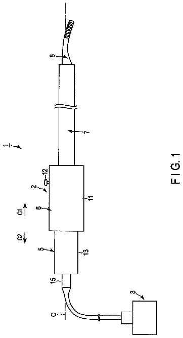
FIG. 1 is a view showing an ultrasonic treatment device according to a first embodiment of the present invention;
FIG. 2 is a schematic view of a vibrating body unit according to the first embodiment seen from a first width direction side;
FIG. 3 is a schematic view of a distal portion of an ultrasonic probe according to the first embodiment seen from the first width direction side;
FIG. 4 is a schematic view of the distal portion of the ultrasonic probe according to the first embodiment seen from a second intersecting direction side;
FIG. 5 is a schematic view of a second curved extending section according to the first embodiment seen from a direction of an arrow V of FIG. 3 ;
FIG. 6 is a schematic view of the second curved extending section according to the first embodiment seen from a first width direction side;
FIG. 7 is a cross-sectional view along the VII-VII line of FIG. 3 ;
FIG. 8 is a schematic view of a state where a bone is cut in a shoulder joint by use of an ultrasonic treatment device according to the first embodiment, which is seen from a front side of the shoulder joint;
FIG. 9 is a schematic view of a state where the bone is cut in the shoulder joint by use of the ultrasonic treatment device according to the first embodiment, which is seen from a rear side of the shoulder joint;
FIG. 10 is a schematic view showing a state where a first cutting surface of a curved extending section of the ultrasonic probe according to the first embodiment is in contact with a lower surface of an acromion;
FIG. 11 is a schematic view showing a state where the first cutting surface of the curved extending section of the ultrasonic probe according to the first embodiment is in contact with a position different from that of FIG. 10 in the lower surface of the acromion;
FIG. 12 is a schematic view showing an amplitude of a longitudinal vibration and stress due to an ultrasonic vibration between a second distal vibration antinode and a most distal vibration antinode in a state where the vibrating body unit according to the first embodiment longitudinally vibrates in an established frequency range;
FIG. 13 is a schematic view of a distal portion of an ultrasonic probe according to a second embodiment seen from a first width direction side;
FIG. 14 is a schematic view of the distal portion of the ultrasonic probe according to the second embodiment seen from a second intersecting direction side;
FIG. 15 is a schematic view of a second curved extending section according to the second embodiment seen from a first width direction side; and
FIG. 16 is a cross-sectional view along the XVI-XVI line of FIG. 15 . DETAILED DESCRIPTION OF THE INVENTION First Embodiment
A first embodiment of the present invention will be described with reference to FIG. 1 to FIG. 12 . FIG. 1 is a view showing an ultrasonic treatment system 1 of the present embodiment. As shown in FIG. 1 , the ultrasonic treatment system 1 includes an ultrasonic treatment instrument (a hand piece) 2 , an energy control device 3 , and a transducer unit 5 . The ultrasonic treatment instrument 2 has a longitudinal axis C. Here, a direction parallel to the longitudinal axis C is a longitudinal axis direction. One side of the longitudinal axis direction is a distal side (an arrow C 1 side of FIG. 1 ), and a side opposite to the distal side is a proximal side (an arrow C 2 side of FIG. 1 ).
The ultrasonic treatment tool 2 includes a holding unit 6 , a sheath 7 , and an ultrasonic probe 8 . The holding unit 6 includes a holding casing 11 to be held by an operator, and an energy operating button 12 that is an energy operation input section attached to the holding casing 11 and configured to be operated by the operator. The sheath 7 that is a hollow tubular member extending along the longitudinal axis C is coupled with the distal side of the holding unit 6 . The ultrasonic probe (a vibration transmitting member) 8 is inserted through the sheath 7 . It is to be noted that a distal portion of the ultrasonic probe 8 projects from a distal end of the sheath 7 toward the distal side.
Furthermore, the transducer unit 5 having a transducer case 13 is coupled with the proximal side of the holding unit 6 . The oscillator unit 5 is connected to one end of a cable 15 . The other end of the cable 15 is connected to the energy control device 3 . The energy control device 3 includes an electric power source, a conversion circuit to convert an electric power from the electric power source into a vibration generating electric power, a processor (a control section) including a CPU (central processing unit) or an ASIC (application specific integrated circuit), and a storage medium such as a memory. Inside the holding casing 11 , there is disposed a switch (not shown) in which an ON/OFF state is changed by an input of an energy operation in the energy operating button 12 . The switch is electrically connected to the processor of the energy control device 3 via a signal route extending through the vibrator unit 5 and an inside of the cable 15 . Furthermore, in the ultrasonic treatment system 1 , a vibrating body unit 20 extends through an inside of the holding casing 11 and an inside of the transducer case 13 .
FIG. 2 is a view showing a constitution of the vibrating body unit 20 . As shown in FIG. 2 , the vibrating body unit 20 includes the ultrasonic probe 8 mentioned above, an ultrasonic transducer 21 that is a vibration generating section constituted of piezoelectric elements, and a relay transmitting member 22 . The ultrasonic oscillator 21 and the relay transmitting member 22 are arranged in the oscillator case 13 , and the relay transmitting member 22 is supported by the transducer case 13 . The ultrasonic transducer 21 is attached to the relay transmitting member 22 . Inside the holding casing 11 , the ultrasonic probe 8 is connected to the distal side of the relay transmitting member 22 . In the relay transmitting member 22 , a sectional area changing portion 23 is disposed in which a sectional area perpendicular to the longitudinal axis C decreases toward the distal side. The sectional area changing portion (a horn portion) 23 is positioned on the distal side with respect to the ultrasonic transducer 21 . The ultrasonic transducer 21 is connected to one end of each of electric wires 25 A and 25 B. The electric wires 25 A and 25 B extend through the inside of the cable 15 , and the other end of the wire is connected to the energy control device 3 .
The switch is switched to an ON state by the input of the energy operation in the energy operating button 12 , whereby in the energy control device 3 , the control section controls the conversion circuit, to supply the vibration generating electric power (a vibration generating current) to the ultrasonic vibrator 21 through the electric wires 25 A and 25 B. Consequently, in the ultrasonic transducer 21 , an ultrasonic vibration occurs, and the generated ultrasonic vibration is transmitted to the ultrasonic probe 8 via the relay transmitting member 22 . In this case, an amplitude of the ultrasonic vibration is enlarged in the sectional area changing portion 23 of the relay transmitting member 22 .
The ultrasonic probe 8 includes a probe main body section 31 extending along the longitudinal axis C. The probe main body section 31 substantially linearly extends along the longitudinal axis C which is an axial center. On the proximal side of the probe main body section 31 , an engagement connecting portion 32 is provided. The engagement connecting portion 32 is engaged in an engagement groove (not shown) disposed in the relay transmitting member 22 (e.g., by screwing an external thread into an internal thread), whereby the probe main body section 31 is connected to the distal side of the relay transmitting member 22 . Thus, the relay transmitting member 22 is connected to the probe main body section 31 , whereby an abutment surface 33 formed at a proximal end of the probe main body section 31 abuts on the relay transmitting member 22 . The ultrasonic vibration is transmitted from the relay transmitting member 22 to the probe main body section 31 through the abutment surface 33 .
Thus, the ultrasonic vibration is transmitted to the probe main body section 31 , whereby in the probe main body section 31 (the ultrasonic probe 8 ), the ultrasonic vibration is transmitted from the proximal side toward the distal side. In a state where the ultrasonic vibration is transmitted through the probe main body section 31 , the vibrating body unit 20 performs a longitudinal vibration in a vibrating direction parallel to the longitudinal axis direction in an established frequency range including an established frequency. In this case, a vibration antinode (the most proximal vibration antinode) A 1 that is one of vibration antinodes of the longitudinal vibration is positioned at a proximal end of the vibrating body unit 20 (a proximal end of the relay transmitting member 22 ), and a vibration antinode (the most distal vibration antinode) A 2 that is one of the vibration antinodes of the longitudinal vibration is positioned at a distal end of the vibrating body unit 20 (a distal end of the ultrasonic probe 8 ). Here, the vibration antinode A 1 is positioned most proximally among the vibration antinodes of the longitudinal vibration, and the vibration antinode A 2 is positioned most distally among the vibration antinodes of the longitudinal vibration. In a certain example, the vibrating body unit 20 is designed in a state of transmitting the ultrasonic vibration therethrough, thereby performing the longitudinal vibration at 47 kHz (the established frequency), and the vibrating body unit actually longitudinally vibrates in the frequency range (the established frequency range) of 46 kHz or more and 48 kHz or less.
The ultrasonic probe 8 has a total length L 1 from its distal end to its proximal end (a proximal end of the engagement connecting portion 32 ) in the longitudinal axis direction. In the certain example, it is preferable that the total length L 1 is 182.9 mm. Furthermore, the ultrasonic probe 8 has a longitudinal dimension L 2 from the distal end to the abutment surface 33 (the proximal end of the probe main body section 31 ) in the longitudinal axis direction. In the certain example, it is preferable that the longitudinal dimension L 2 is 177.5 mm.
In the probe main body section 31 , a horn portion (a first horn portion) 35 is disposed. In the horn portion 35 , the sectional area perpendicular to the longitudinal axis C decreases toward the distal side. The horn portion (a sectional area decreasing portion) 35 is positioned on the distal side with respect to the abutment surface 33 , and the probe main body section 31 has a longitudinal dimension L 3 from the abutment surface 33 to a proximal end (a vibration input end) E 1 of the horn portion 35 in the longitudinal axis direction. In the certain example, it is preferable that the longitudinal dimension L 3 is 29 mm. Furthermore, the horn portion (the first horn portion) 35 has a horn longitudinal dimension (a first horn longitudinal dimension) L 4 from the proximal end (the vibration input end) E 1 to a distal end (a vibration output end) E 2 in the longitudinal axis direction. In the certain example, it is preferable that the horn longitudinal dimension L 4 is 20 mm.
An outer diameter of the probe main body section 31 is kept to be substantially constant from the abutment surface 33 to the proximal end E 1 of the horn portion 35 in the longitudinal axis direction. Therefore, the probe main body section 31 has an outer diameter D 1 in the abutment surface 33 and at the proximal end E 1 of the horn portion 35 . In the certain example, it is preferable that the outer diameter D 1 is 7 mm. Furthermore, in the horn portion 35 , a sectional area decreases toward the distal side, and hence at the distal end E 2 of the horn portion 35 , the probe main body section 31 has an outer diameter D 2 smaller than the outer diameter D 1 . That is, in the horn portion 35 , the outer diameter of the probe main body section 31 decreases from the outer diameter D 1 to the outer diameter D 2 toward the distal side. In the certain example, it is preferable that the outer diameter D 2 is 3.8 mm.
In a state where the vibrating body unit 20 longitudinally vibrates in the predetermined frequency range (e.g., 46 kHz or more and 48 kHz or less), a vibration node N 1 that is one of vibration nodes of the longitudinal vibration is positioned at the proximal end E 1 of the horn portion 35 or in the vicinity of the proximal end E 1 , and each of the vibration antinodes of the longitudinal vibration is positioned away from the horn portion 35 in the longitudinal axis direction.
Consequently, in the horn portion 35 in which the sectional area decreases toward the distal side, the amplitude of the longitudinal vibration (the ultrasonic vibration) is enlarged. In the certain example, the longitudinal vibration in which the amplitude at the vibration antinode is 18 μm is transmitted to the proximal end E 1 of the horn portion 35 , and the amplitude of the longitudinal vibration in the horn portion 35 is enlarged. It is to be noted that in a state where the vibrating body unit 20 longitudinally vibrates at the predetermined frequency (e.g., 47 kHz) included in the predetermined frequency range, the vibration node N 1 is positioned at the proximal end E 1 of the horn portion 35 .
In the probe main body section 31 , a horn portion (a second horn portion) 36 is provided. In the horn portion 36 , the sectional area perpendicular to the longitudinal axis C decreases toward the distal side. The horn portion (a sectional area decreasing portion) 36 is positioned on the distal side from the horn portion (the first horn portion) 35 , and the probe main body section 31 has a longitudinal dimension L 5 from the abutment surface 33 to a proximal end (a vibration input end) E 3 of the horn portion 36 in the longitudinal axis direction. In the certain example, it is preferable that the longitudinal dimension L 5 is 88.1 mm. Furthermore, the horn portion (the second horn portion) 36 has a horn longitudinal dimension (a second horn longitudinal dimension) L 6 from the proximal end (the vibration input end) E 3 to a distal end (a vibration output end) E 4 in the longitudinal axis direction. In the certain example, it is preferable that the horn longitudinal dimension L 6 is 14 mm.
In the probe main body section 31 , the outer diameter is kept to be substantially constant from the distal end E 2 of the horn portion (the first horn portion) 35 to the proximal end E 3 of the horn portion (the second horn portion) 36 in the longitudinal axis direction. Therefore, the probe main body section 31 has the outer diameter D 2 at the proximal end E 3 of the horn portion 36 . That is, at the distal end E 2 of the horn portion 35 and the proximal end E 3 of the horn portion 36 , the outer diameter of the probe main body section 31 becomes the outer diameter D 2 and has about the same size. Furthermore, in the horn portion 36 , the sectional area decreases toward the distal side, and hence at the distal end E 4 of the horn portion 36 , the probe main body section 31 has an outer diameter D 3 that is smaller than the outer diameter D 2 . That is, in the horn portion 36 , the outer diameter of the probe main body section 31 decreases from the outer diameter D 2 to the outer diameter D 3 toward the distal side. In the certain example, it is preferable that the outer diameter D 3 is 2.7 mm.
In the state where the vibrating body unit 20 longitudinally vibrates in the established frequency range (e.g., 46 kHz or more and 48 kHz or less), a vibration node N 2 that is one of the vibration nodes of the longitudinal vibration is positioned at the proximal end E 3 of the horn portion 36 or in the vicinity of the proximal end E 3 , and each of the vibration antinodes of the longitudinal vibration is positioned away from the horn portion 36 in the longitudinal axis direction. Consequently, in the horn portion 36 in which the sectional area decreases toward the distal side, the amplitude of the longitudinal vibration (the ultrasonic vibration) is enlarged. It is to be noted that in the state where the vibrating body unit 20 longitudinally vibrates at the established frequency (e.g., 47 kHz) included in the established frequency range, the vibration node N 2 is positioned at the proximal end E 3 of the horn portion 36 . Furthermore, in the state where the vibrating body unit 20 longitudinally vibrates in the predetermined frequency range, the vibration node N 2 is positioned on the distal side with respect to the vibration node N 1 .
In the probe main body section 31 , a sectional area increasing portion 37 is provided. In the sectional area increasing portion 37 , the sectional area perpendicular to the longitudinal axis C increases toward the distal side. The sectional area increasing portion 37 is positioned on the distal side with respect to the horn portion (the second horn portion) 36 , and the probe main body section 31 has a longitudinal dimension L 7 from the abutment surface 33 to a distal end (a vibration output end) E 6 of the sectional area increasing portion 37 in the longitudinal axis direction. In the certain example, it is preferable that the longitudinal dimension L 7 is 116.7 mm.
Furthermore, the sectional area increasing portion 37 has an extending dimension L 8 from a proximal end (a vibration input end) E 5 to the distal end (the vibration output end) E 6 in the longitudinal axis direction. The extending dimension L 8 is small, and hence in the sectional area increasing portion 37 , a distance from the proximal end E 5 to the distal end E 6 decreases.
In the probe main body section 31 , the outer diameter is kept to be substantially constant from the distal end E 4 of the horn portion (the second horn portion) 36 to the proximal end E 5 of the sectional area increasing portion 37 in the longitudinal axis direction. Therefore, the probe main body section 31 has the outer diameter D 3 at the proximal end E 5 of the sectional area increasing portion 37 . That is, at the distal end E 4 of the horn portion 36 and the proximal end E 5 of the sectional area increasing portion 37 , the outer diameter of the probe main body section 31 becomes the outer diameter D 3 and has about the same size. Furthermore, in the sectional area increasing portion 37 , the sectional area increases toward the distal side, and hence at the distal end 16 of the sectional area increasing portion 37 , the probe main body section 31 has an outer diameter D 4 that is larger than the outer diameter D 3 . That is, in the sectional area increasing portion 37 , the outer diameter of the probe main body section 31 increases from the outer diameter D 3 to the outer diameter D 4 toward the distal side. In the certain example, the outer diameter D 4 is about the same as the outer diameter D 2 at the proximal end 13 of the horn portion 36 . In this case, it is preferable that the outer diameter D 4 is 3.8 mm.
In the state where the vibrating body unit 20 longitudinally vibrates in the established frequency range, a vibration antinode A 3 that is one of the vibration antinodes of the longitudinal vibration is positioned in the sectional area increasing portion 37 . The vibration antinode A 3 at which stress due to the ultrasonic vibration becomes zero is positioned in the sectional area increasing portion 37 , and hence, also in the sectional area increasing portion 37 in which the sectional area increases toward the distal side, the amplitude of the longitudinal vibration (the ultrasonic vibration) hardly decreases. It is to be noted that in the state where the vibrating body unit 20 longitudinally vibrates in the established frequency range, the vibration antinode A 3 is positioned on the distal side with respect to the vibration node N 2 , and in the present embodiment, the vibration antinode A 3 is positioned second distally among the vibration antinodes of the longitudinal vibration.
The probe main body section 31 includes a supported portion 38 to be supported by the sheath 7 via an elastic member (not shown). The supported portion 38 is positioned on the distal side with respect to the sectional area increasing portion 37 . The probe main body section 31 has a longitudinal dimension L 9 from the distal end E 6 of the sectional area increasing portion 37 to a proximal end E 7 of the supported portion 38 in the longitudinal axis direction. In the certain example, it is preferable that the longitudinal dimension L 9 is 24.1 mm. Furthermore, the supported portion 38 has an extending dimension L 10 from the proximal end E 7 to a distal end E 8 in the longitudinal axis direction. The extending dimension L 10 is small, and in the certain example, it is preferable that the extending dimension L 10 is 3 mm.
In the probe main body section 31 , the outer diameter is kept to be substantially constant from the distal end E 6 of the sectional area increasing portion 37 to the proximal end E 7 of the supported portion 38 in the longitudinal axis direction. Therefore, the probe main body section 31 has the outer diameter D 4 at the proximal end E 7 of the supported portion 38 . That is, at the distal end E 6 of the sectional area increasing portion 37 and the proximal end E 7 of the supported portion 38 , the outer diameter of the probe main body section 31 becomes the outer diameter D 4 and has about the same size. In a proximal portion of the supported portion 38 , the outer diameter of the probe main body section 31 decreases from the outer diameter D 4 to an outer diameter D 5 . In the certain example, the outer diameter D 5 is about 0.4 mm smaller than the outer diameter D 4 . In the supported portion 38 , the outer diameter of the probe main body section 31 is kept to be substantially constant at the outer diameter D 5 along a large part in the longitudinal axis direction. Further, in the distal portion of the supported portion 38 , the outer diameter of the probe main body section 31 increases from the outer diameter D 5 to an outer diameter D 6 . In consequence, the probe main body section 31 has the outer diameter D 6 at the distal end E 8 of the supported portion 38 . The outer diameter D 6 at the distal end E 8 of the supported portion 38 is about the same as the outer diameter D 4 at the proximal end E 7 of the supported portion 38 . Consequently, at the proximal end E 7 and the distal end E 8 of the supported portion 38 , the sectional area of the probe main body section 31 which is perpendicular to the longitudinal axis C becomes about the same. In the certain example, it is preferable that the outer diameter D 6 is 3.8 mm.
In the state where the vibrating body unit 20 longitudinally vibrates in the established frequency range, a vibration node N 3 that is one of the vibration nodes of the longitudinal vibration is positioned in the supported portion 38 . Consequently, the probe main body section 31 (the ultrasonic probe 8 ), which longitudinally vibrates, is also attached to the sheath 7 via the elastic member in the supported portion 38 . Furthermore, the probe main body section is supported by the sheath 7 at the vibration node N 3 of the longitudinal vibration, and hence in the state where the vibrating body unit 20 longitudinally vibrates in the predetermined frequency range, transmission of the ultrasonic vibration from the supported portion 38 to the sheath 7 is prevented. In the state where the vibrating body unit 20 longitudinally vibrates in the established frequency range, the vibration node (the most distal vibration node) N 3 is positioned on the distal side with respect to the vibration node N 2 , and is positioned most distally among the vibration nodes of the longitudinal vibration. Furthermore, at the proximal end E 7 and the distal end E 8 of the supported portion 38 , the sectional area of the probe main body section 31 which is perpendicular to the longitudinal axis C becomes about the same, and hence in the supported portion 38 , the amplitude of the longitudinal vibration hardly changes.
Furthermore, the distal end of the sheath 7 is positioned on the distal side from the distal end 58 of the supported portion 38 . Therefore, in the state where the vibrating body unit 20 longitudinally vibrates in the established frequency range, the vibration node N 3 positioned most distally among the vibration nodes is positioned inside the sheath 7 .
FIG. 3 and FIG. 4 are views showing a constitution of the distal portion of the ultrasonic probe 8 . Here, a certain direction that intersects (is substantially perpendicular to) the longitudinal axis C is a first intersecting direction (a direction of an arrow P 1 in each of FIG. 2 and FIG. 3 ), and an opposite direction to the first intersecting direction (a first vertical direction) is a second intersecting direction (a direction of an arrow P 2 in each of FIG. 2 and FIG. 3 ). Furthermore, one of two directions which intersect the longitudinal axis C (substantially perpendicularly) and are perpendicular to (intersect) the first intersecting direction (the first perpendicular direction) and the second intersecting direction (a second perpendicular direction) is a first width direction (a direction of an arrow B 1 in FIG. 4 ). Further, an opposite direction to the first width direction is a second width direction (a direction of an arrow B 2 in FIG. 4 ). Here, FIG. 2 and FIG. 3 are views of the ultrasonic probe 8 seen from a first width direction side, and FIG. 4 is a view of the ultrasonic probe 8 seen from a second perpendicular direction side. It is to be noted that in FIG. 3 , a range shown by a broken line S 1 and a broken line S 2 projects from the distal end of the sheath 7 toward the distal side.
As shown in FIG. 3 and FIG. 4 , the probe main body section 31 extends to a position located on the distal side with respect to the supported portion 38 . That is, a distal end E 9 of the probe main body section 31 is positioned on the distal side from the distal end E 8 of the supported portion 38 . However, a distance between the distal end E 8 of the supported portion 38 and the distal end E 9 of the probe main body section 31 in the longitudinal axis direction is small, and is about 0.6 mm in the certain example.
As described above, in the probe main body section 31 , the amplitude of the longitudinal vibration is enlarged in the horn portion (the first horn portion) 35 and the horn portion (the second horn portion) 36 , and the amplitude of the longitudinal vibration hardly changes in the sectional area increasing portion 37 and the supported portion 38 . Due to the above-mentioned constitution, in the certain example, the longitudinal vibration of an amplitude of 80 μm occurs at the distal end E 9 of the probe main body section 31 , in a case where the longitudinal vibration of an amplitude of 18 μm at the vibration antinode is transmitted to the proximal end (the abutment surface 33 ) of the probe main body section 31 .
A tapered section (a sectional area decreasing portion) 41 is continuous on the distal side of the probe main body section 31 . In the tapered section (a third horn portion) 41 , a sectional area perpendicular to a longitudinal axis C decreases toward the distal side. A proximal end of the tapered section 41 is continuous with the distal end E 9 of the probe main body section 31 . Therefore, the distal end E 9 of the probe main body section 31 becomes a boundary position between the probe main body section 31 and the tapered section 41 . The ultrasonic probe 8 has a longitudinal dimension L 11 from the distal end to the proximal end (E 9 ) of the tapered section 41 in the longitudinal axis direction. In the certain example, it is preferable that the longitudinal dimension L 11 is 32.5 mm.
The tapered section 41 includes a first narrowed outer surface 51 facing a first intersecting direction side. In the tapered section 41 , a distance (a first distance) δ from the longitudinal axis C to the first narrowed outer surface 51 in a first intersecting direction decreases from a proximal side toward the distal side, between the proximal end (E 9 ) and a first narrowing end position (a first distance decreasing end position) E 10 in the longitudinal axis direction. The first narrowing end position E 10 is positioned on the distal side with respect to the proximal end (E 9 ) of the tapered section 41 . Consequently, the tapered section 41 has a first narrowing dimension (a first distance decreasing dimension) L 12 between the proximal end (E 9 ) and the first constricting end position E 10 in the longitudinal axis direction. In the certain example, it is preferable that the first narrowing dimension L 12 is 18 mm. In the present embodiment, the proximal end (E 9 ) of the tapered section 41 becomes a proximal end of the first narrowed outer surface 51 , and the first narrowing end position E 10 becomes a distal end of the first narrowed outer surface 51 .
Furthermore, the tapered section 41 includes a second narrowed outer surface 52 facing the second intersecting direction side. On the tapered section 41 , a distance (a second distance) δ′ from the longitudinal axis C to the second narrowed outer surface 52 in a second intersecting direction decreases from the proximal side toward the distal side, between the proximal end (E 9 ) and a second narrowing end position (a second distance decreasing end position) E 11 in the longitudinal axis direction. The second narrowing end position E 11 is positioned on the distal side with respect to the first narrowing end position E 10 . Consequently, the tapered section 41 has a second narrowing dimension (a second distancing decrease dimension) L 13 that is larger than the first narrowing dimension L 12 , between the proximal end (E 9 ) and the second narrowing end position E 11 in the longitudinal axis direction. In the certain example, it is preferable that the second constricting dimension L 13 is 23 mm. In the present embodiment, the proximal end (E 9 ) of the tapered section 41 becomes a proximal end of the second narrowed outer surface 52 , and the second narrowing end position E 11 becomes a distal end of the second constricted outer surface 52 . Consequently, in the tapered section 41 , the distal end of the first constricted outer surface 51 (the first constricting end position E 10 ) is positioned on a proximal side as compared with the distal end of the second narrowed outer surface 52 (the second narrowing end position E 11 ), and the distal end of the first narrowed outer surface 51 is disposed away from the distal end of the second narrowed outer surface 52 in the longitudinal axis direction.
Due to the above-mentioned constitution, in the tapered section 41 , a thickness (a dimension) T of the ultrasonic probe 8 in the first intersecting direction and the second intersecting direction decreases toward the distal side, between the proximal end (E 9 ) and the second narrowing end position E 11 in the longitudinal axis direction. Therefore, the proximal end (E 9 ) of the tapered section 41 becomes a thickness decreasing start position, and the second narrowing end position E 11 becomes a thickness decreasing end position. Furthermore, in projection from a first width direction (one side of a width direction), a first narrowing angle α 1 that is a narrowing angle (an acute angle) of the first narrowed outer surface 51 relative to the longitudinal axis direction is larger than a second narrowing angle α 2 that is a narrowing angle (an acute angle) of the second narrowed outer surface 52 relative to the longitudinal axis direction, and the first narrowing angle is different from the second narrowing angle α 2 .
Furthermore, the tapered section 41 includes a third narrowed outer surface 53 directed in the first width direction, and a fourth narrowed outer surface 54 facing a second width direction. In the tapered section 41 , between a width decreasing start position E 12 and a width decreasing end position E 13 in the longitudinal axis direction, a distance from the longitudinal axis C to the third narrowed outer surface 53 in the first width direction and a distance from the longitudinal axis C to the fourth narrowed outer surface 54 in the second width direction decrease from the proximal side toward the distal side. Consequently, in the tapered section 41 , a width (a dimension) W of the ultrasonic probe 8 in the first width direction and the second width direction decreases toward the distal side, between the width decreasing start position E 12 and the width decreasing end position E 13 in the longitudinal axis direction. The ultrasonic probe 8 has a longitudinal dimension L 14 from the distal end to the width decreasing start position E 12 in the longitudinal axis direction. The longitudinal dimension L 14 is smaller than the longitudinal dimension L 11 from the distal end of the ultrasonic probe 8 to the proximal end (E 9 ) of the tapered section 41 in the longitudinal axis direction. Therefore, the width decreasing start position E 12 is positioned on the distal side with respect to the proximal end (E 9 ) of the tapered section 41 . However, the distance between the proximal end (E 9 ) of the tapered section 41 and the width decreasing start position E 12 in the longitudinal axis direction is small. In the certain example, it is preferable that the longitudinal dimension L 14 is 32 mm. Further, in this example, the distance between the proximal end (E 9 ) of the tapered section 41 and the width decreasing start position E 12 in the longitudinal axis direction is about 0.5 mm. In the present embodiment, the width decreasing start position E 12 becomes a proximal end of each of the third constricted outer surface 53 and the fourth constricted outer surface 54 , and the width decreasing end position E 13 becomes a distal end of each of the third narrowed outer surface 53 and the fourth narrowed outer surface 54 .
The ultrasonic probe 8 has a longitudinal dimension L 15 from the distal end to the width decreasing end position E 13 in the longitudinal axis direction. In the present embodiment, the width decreasing end position E 13 is positioned on the distal side with respect to the second narrowing end position E 11 . Further, the width decreasing end position E 13 becomes a distal end of the tapered section 41 . However, a distance between the second narrowing end position (the distal end of the second narrowed outer surface 52 ) E 11 and the width decreasing end position E 13 in the longitudinal axis direction is small. In the certain example, it is preferable that the longitudinal dimension L 15 is 9 mm. Further, in this example, the distance between the second narrowing end position E 11 and the width decreasing end position 513 in the longitudinal axis direction is about 0.5 mm.
The distance (the first distance) δ from the longitudinal axis C to the first narrowed outer surface 51 (an outer peripheral surface of the ultrasonic probe 8 ) in the first intersecting direction (a first perpendicular direction) decreases down to a distance δ 1 , between the proximal end (E 9 ) of the tapered section 41 and the first narrowing end position E 10 in the longitudinal axis direction. Therefore, at the first narrowing end position (the distal end of the first narrowed outer surface 51 ) E 10 , the ultrasonic probe 8 has the distance (the first distance) δ 1 from the longitudinal axis C to the first narrowed outer surface 51 toward the first intersecting direction. The distance δ 1 is smaller than a value of ½ of the outer diameter D 6 at the distal end E 9 of the probe main body section 31 . In the certain example, the distance δ 1 is 0.45 mm or more and 0.5 mm or less.
Between the proximal end (E 9 ) of the tapered section 41 and the second narrowing end position E 11 in the longitudinal axis direction, the thickness (the dimension) T of the ultrasonic probe 8 in the first intersecting direction and the second intersecting direction decreases down to a thickness T 1 . Therefore, at the second narrowing end position (the distal end of the second narrowed outer surface 52 ) E 11 , the ultrasonic probe 8 has the thickness T 1 in the first intersecting direction (the first perpendicular direction) and the second intersecting direction (a second perpendicular direction). The thickness T 1 is smaller than the outer diameter D 6 at the distal end E 9 of the probe main body section 31 . In the certain example, it is preferable that the thickness T 1 is 1.65 mm.
The description continues in the full USPTO document.
 Lapsed, fee not paid3 drawings