Background
Field of the Disclosure
The present disclosure relates to wireless communication systems, and more particularly to managing resource allocations for random access procedure in a cellular Internet of Things (IoT) system.
Description of Related Art
Wireless communication systems are widely deployed to provide various types of communication content such as voice, video, packet data, messaging, broadcast, and so on. These systems may be multiple-access systems capable of supporting communication with multiple users by sharing the available system resources (e.g., time, frequency, and power). Examples of such multiple-access systems include code-division multiple access (CDMA) systems, time-division multiple access (TDMA) systems, frequency-division multiple access (FDMA) systems, and orthogonal frequency-division multiple access (OFDMA) systems.
By way of example, a wireless multiple-access communication system may include a number of base stations, each simultaneously supporting communication for multiple communication devices, otherwise known as user equipment (UE). A base station may communicate with UEs on downlink channels (e.g., for transmissions from a base station to a UE) and uplink channels (e.g., for transmissions from a UE to a base station).
Some UEs may provide for automated communication. Automated UEs may include those implementing Machine-to-Machine (M2M) communication or Machine Type Communication (MTC). M2M or MTC may refer to data communication technologies that allow devices to communicate with one another or a base station without human intervention. M2M or MTC devices may include UEs and may be used as part of an Internet of Things (IoT). Some M2M or MTC devices in an IoT may include parking meters, water and gas meters, and other sensors that may infrequently communicate small amounts of data.
Therefore, communication requirements of an M2M or MTC device in an IoT network may be significantly lower than those typically required by a non-IoT device (e.g., cell phone). For instance, a non-IoT device (e.g., a cell phone) that may be constantly in motion may require high data rates to support low latency in its voice and data communications. Consequently, when existing cellular systems and protocols are used for IoT devices, the IoT devices may be subject to communication requirements and overhead that are unnecessary and even undesirable, resulting in excessive power drain of the IoT devices.
Summary
Systems, methods, and apparatus for managing resource allocation for random access procedure in an IoT system are described. In accordance with the present disclosure, a base station may allocate, to a UE, time and/or frequency resources for transmitting physical random access channel (PRACH) signals. In some examples, the resource allocation may be apportioned based on a type and class of PRACH signal. For instance, a UE may be assigned a first subset of resources to transmit regularly scheduled traffic and a second subset of resources to transmit on-demand traffic. Regularly scheduled traffic may include, for example, sensor measurements reported to the base station on a predetermined time interval (e.g., 24 hour time interval). In contrast, on-demand traffic may include an impromptu transmission, initiated based on a detection of at least one reporting trigger (e.g., sensing an abnormality at the UE).
Additionally or alternatively, the present disclosure may also relate to reporting a path loss information to the base station in a PRACH signal. In some examples, the path loss information may be determined by receiving a downlink signal from the base station and measuring the strength of the downlink signal.
A method of wireless communication at a UE is described. The method may include receiving, from a base station, a first allocation of resources for sending a first PRACH signal for regularly scheduled transmission, wherein the first allocation of resources includes at least one of a time or a frequency resource, detecting a first reporting trigger for the regularly scheduled transmission, and transmitting, in response to detecting the reporting trigger, the first PRACH signal to the base station over the first allocation of resources.
An apparatus for wireless communication at a UE is described. The apparatus may include means for receiving, from a base station, a first allocation of resources for sending a first PRACH signal for regularly scheduled transmission, wherein the first allocation of resources includes at least one of a time or a frequency resource, means for detecting a first reporting trigger for the regularly scheduled transmission, and means for transmitting, in response to detecting the reporting trigger, the first PRACH signal to the base station over the first allocation of resources.
A further apparatus for wireless communication at a UE is described. The apparatus may include a processor, memory in electronic communication with the processor, and instructions stored in the memory, wherein the instructions are executable by the processor to receive, from a base station, a first allocation of resources for sending a first PRACH signal for regularly scheduled transmission, wherein the first allocation of resources includes at least one of a time or a frequency resource, detect a first reporting trigger for the regularly scheduled transmission, and transmit, in response to detecting the reporting trigger, the first PRACH signal to the base station over the first allocation of resources.
A non-transitory computer-readable medium storing code for wireless communication at a UE is described. The code may include instructions executable to receive, from a base station, a first allocation of resources for sending a first PRACH signal for regularly scheduled transmission, wherein the first allocation of resources includes at least one of a time or a frequency resource, detect a first reporting trigger for the regularly scheduled transmission, and transmit, in response to detecting the reporting trigger, the first PRACH signal to the base station over the first allocation of resources.
Some examples of the method, apparatuses, or non-transitory computer-readable medium described above may further include determining a path loss information associated with the base station, and reporting the path loss information to the base station in the first PRACH signal. Additionally or alternatively, in some examples the path loss information is determined by receiving a downlink signal from the base station and measuring strength of the downlink signal.
Some examples of the method, apparatuses, or non-transitory computer-readable medium described above may further include receiving, from the base station, a second allocation of resources for sending a second PRACH signal for an on-demand transmission, detecting a second reporting trigger for the on-demand transmission, and transmitting the second PRACH signal to the base station based on the detecting, the second PRACH signal transmitted over the first allocation of resources or the second allocation of resources. Additionally or alternatively, in some examples the on-demand transmission is assigned a higher priority than the regularly scheduled transmission.
In some examples of the method, apparatuses, or non-transitory computer-readable medium described above, the first and second allocation of resource fail to overlap. Additionally or alternatively, in some examples the first allocation of resource is a subset of the second allocation of resources.
Some examples of the method, apparatuses, or non-transitory computer-readable medium described above may further include receiving an access level information from the base station, the access level information associated with the regularly scheduled transmission and the on-demand transmission, determining whether access priority for at least one of the first PRACH signal or the second PRACH signal is above the access level information, and transmitting the first PRACH signal or the second PRACH signal based on the determining. Additionally or alternatively, in some examples the access level information is based on a loading factor of the first allocation of resources and the second allocation of resources.
Some examples of the method, apparatuses, or non-transitory computer-readable medium described above may further include receiving, in response to the first PRACH signal, a PRACH response from the base station, and determining an active ID for the UE based in part on the PRACH response. Additionally or alternatively, some examples may include using the active ID for physical downlink shared channel (PDSCH) and PUSCH assignments.
Some examples of the method, apparatuses, or non-transitory computer-readable medium described above may further include transmitting a request for a PUSCH in the first PRACH signal using at least one of the first allocation of resources or the second allocation of resources. Additionally or alternatively, some examples may include exchanging data with a network based on machine type communication (MTC) procedures.
The foregoing has outlined rather broadly the features and technical advantages of examples according to the disclosure in order that the detailed description that follows may be better understood. Additional features and advantages will be described hereinafter. The conception and specific examples disclosed may be readily utilized as a basis for modifying or designing other structures for carrying out the same purposes of the present disclosure. Such equivalent constructions do not depart from the scope of the appended claims. Characteristics of the concepts disclosed herein, both their organization and method of operation, together with associated advantages will be better understood from the following description when considered in connection with the accompanying figures. Each of the figures is provided for the purpose of illustration and description only, and not as a definition of the limits of the claims.
Brief description of the drawings
A further understanding of the nature and advantages of the present invention may be realized by reference to the following drawings. In the appended figures, similar components or features may have the same reference label. Further, various components of the same type may be distinguished by following the reference label by a dash and a second label that distinguishes among the similar components. If only the first reference label is used in the specification, the description is applicable to any one of the similar components having the same first reference label irrespective of the second reference label.
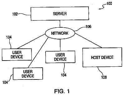
FIG. 1 shows a block diagram of a wireless communication system, in accordance with various aspects of the present disclosure;
FIG. 2 illustrates an example of managing resource allocations for random access procedure in a cellular IoT wireless system;
FIG. 3 illustrates an example of a frame structure for managing resource allocations for random access procedure in a cellular IoT wireless system;
FIG. 4 illustrates a communication diagram between a base station and a UE for managing resource allocations for random access procedure in a cellular IoT wireless system
FIG. 5 shows a block diagram of a device configured for use in wireless communication, in accordance with various aspects of the present disclosure;
FIG. 6 shows a block diagram of a device configured for use in wireless communication, in accordance with various aspects of the present disclosure;
FIG. 7 shows a block diagram of a communication management module configured for random access procedure in a cellular internet of things system in accordance with various aspects of the present disclosure;
FIG. 8 illustrates a block diagram of a system including a UE configured for random access procedure in a cellular internet of things system in accordance with various aspects of the present disclosure;
FIG. 9 shows a flowchart illustrating a method for random access procedure in a cellular internet of things system in accordance with various aspects of the present disclosure;
FIG. 10 shows a flowchart illustrating a method for random access procedure in a cellular internet of things system in accordance with various aspects of the present disclosure;
FIG. 11 shows a flowchart illustrating a method for random access procedure in a cellular internet of things system in accordance with various aspects of the present disclosure;
FIG. 12 shows a flowchart illustrating a method for random access procedure in a cellular internet of things system in accordance with various aspects of the present disclosure;
FIG. 13 shows a flowchart illustrating a method for random access procedure in a cellular internet of things system in accordance with various aspects of the present disclosure; and
FIG. 14 shows a flowchart illustrating a method for random access procedure in a cellular internet of things system in accordance with various aspects of the present disclosure.
Detailed description
As discussed above, M2M or MTC device(s) in an IoT network generally require significantly lower communication resources than those typically required by a non-IoT device. For example, a UE in an IoT network may be configured to infrequently transmit small amounts of data on regularly scheduled intervals. In one example, a UE may be instructed to report at least one sensor measurement once every 24 hour time interval. Intermittently, the UE may also transmit impromptu traffic if the UE detects at least one on-demand reporting trigger (e.g., if UE senses an abnormality). As a result, it may be counterintuitive for a UE that may be limited in power resources (i.e., battery) to contend for resources or to unnecessarily occupy resources (e.g., transmission medium) during such minimal transmission periods.
In accordance with the present disclosure, a base station may allocate certain time or frequency resources to the UE for transmitting on the network. The resource allocation may be based on the type and class of the traffic scheduled for transmission. In some examples, the type and class of the traffic may be associated with a regularly scheduled transmission or an on-demand transmission. Accordingly, a UE in an IoT network may utilize the allocated resources for transmitting PRACH signal(s) based on the type and class of the PRACH signal (i.e., regularly scheduled PRACH signal or on-demand PRACH signal).
Additionally or alternatively, the base station may transmit access level information to the UE, where the access level information identifies a priority level for each of the regularly scheduled class of traffic and on-demand class of traffic. Consequently, the access level information may moderate resource contention(s) between different types of classes. In one example, the on-demand class may be assigned a higher priority than a regularly scheduled class. Thus, during a potential contention of resources between transmission of a regularly scheduled class of traffic and an on-demand class of traffic, the UE may favor the on-demand traffic based on the priority level identified by the access level information. In other examples, the regularly scheduled class of traffic may be assigned a higher priority than the on-demand class.
In a yet further example of the present disclosure, the UE in an IoT may determine path loss information associated with the base station. In some examples, the path loss information may be determined by receiving a downlink signal from the base station and measuring the strength of the downlink signal. Accordingly, in order to synchronize with the base station, the UE may transmit the path loss information to the base station in a PRACH signal. In some examples, the base station may utilize the path loss information to determine the downlink power and manage resources for downlink control and traffic channels (e.g., Physical Downlink Control Channel (PDCCH) and Physical Downlink Shared Channel (PDSCH)).
In other cases, communication between an IoT device and a base station may be improved by using open loop timing synchronization to determine transmit symbol time. As a result, uplink signals from different IoT devices communicating with a same base station in the IoT network may arrive within a window of time, the length of which may be up to the maximum round-trip delay between the IoT devices and the base station. To account for this, the length of a cyclic prefix used in an uplink transmission by an IoT device may be extended, while the length of a cyclic prefix used in a downlink transmission to the IoT device may remain shorter than the extended uplink cyclic prefix.
In some examples, a device may utilize orthogonal frequency division multiple access (OFDMA) for demodulating downlink messages and a combination of Gaussian minimum shift keying (GMSK) and single carrier frequency division multiple access (SC-FDMA) for uplink modulation. The uplink modulation process may include generating a symbol vector with an M-point discrete Fourier transform (DFT), filtering the symbol vector with a frequency domain Gaussian filter, generating a sample vector from the filtered symbol vector utilizing an inverse DFT, and modulating the sample vector utilizing GMSK. In some cases, the uplink modulation may be based on a narrowband resource allocation received from a base station
In some examples, a device may synchronize with a cell using a waveform known to the UE beforehand, and common to a group of cells in the local region. The device may then determine a physical broadcast channel (PBCH) time. The device may receive the PBCH and use it to determine a physical layer ID for the cell and a frequency for uplink transmissions. The PBCH may also indicate a channel configuration, which may enable the device to perform a random access procedure. The channel configuration may include a time and frequency resource configuration of a shared traffic channel. In some cases, the device may determine resources for data transmission based on an index of a control channel transmission. In some cases, there may be a predetermined delay between control channel transmissions and data channel transmissions. The device may then enter a low power state during the delay.
In some examples, a device may perform an initial access procedure to establish a connection with a serving cell. The device may then arrange a regular transmission schedule with the serving cell including a discontinuous transmission (DTX) cycle and an acknowledgement schedule. The device may enter a low power mode and refrain from any transmission during the a sleep interval of the DTX cycle. The device may then wake up and transmit a message to the serving cell after the sleep interval without performing an another access procedure. The device may perform another access procedure to transmit at times not covered by the regular transmission schedule. For example, if an acknowledgement (ACK) for the message isn't received, the device may perform another access procedure for retransmission.
In yet another example, an IoT device may use stored control information from a first communication session with the base station to determine the power and timing control information for a subsequent second communication session. Specifically, in this example, a device may establish a first communication session with the base station and receive, during the first communication session, closed loop control information from the base station to aid the device in adjusting transmit signal symbol timing and/or power control levels associated with an uplink transmission. In such instance, the device may store, in its memory, the transmit power and symbol timing information derived from the closed loop control information during the first communication session. Subsequently, the device may utilize the stored closed loop control information from the first communication session to determine the transmit signal power and/or symbol timing to establish a second communication session with the base station.
The following description provides examples, and is not limiting of the scope, applicability, or examples set forth in the claims. Changes may be made in the function and arrangement of elements discussed without departing from the scope of the disclosure. Various examples may omit, substitute, or add various procedures or components as appropriate. For instance, the methods described may be performed in an order different from that described, and various steps may be added, omitted, or combined. Also, features described with respect to some examples may be combined in other examples.
FIG. 1 illustrates an example of a wireless communications system 100 in accordance with various aspects of the disclosure. The wireless communications system 100 includes base stations 105 , UEs 115 , and a core network 130 . The core network 130 may provide user authentication, access authorization, tracking, Internet Protocol (IP) connectivity, and other access, routing, or mobility functions. The base stations 105 interface with the core network 130 through backhaul links 132 (e.g., S1, etc.) and may perform radio configuration and scheduling for communication with the UEs 115 , or may operate under the control of a base station controller (not shown). In various examples, the base stations 105 may communicate, either directly or indirectly (e.g., through core network 130 ), with each other over backhaul links 134 (e.g., X1, etc.), which may be wired or wireless communication links.
The base stations 105 may wirelessly communicate with the UEs 115 via one or more base station antennas. Each of the base station 105 sites may provide communication coverage for a respective geographic coverage area 110 . In accordance with the present disclosure, the term “coverage area” and “cell” may be used interchangeably to refer to the geographic coverage area 110 . In some examples, base stations 105 may be referred to as a base transceiver station, a radio base station, an access point, a radio transceiver, a NodeB, eNodeB (eNB), Home NodeB, a Home eNodeB, or some other suitable terminology. The geographic coverage area 110 for a base station 105 may be divided into sectors making up only a portion of the coverage area (not shown). The wireless communications system 100 may include base stations 105 of different types (e.g., macro and/or small cell base stations). There may be overlapping geographic coverage areas 110 for different technologies.
In some examples, the wireless communications system 100 may be or include an LTE/LTE-A network. In LTE/LTE-A networks, the term evolved Node B (eNB) may be generally used to describe the base stations 105 , while the term UE may be generally used to describe the UEs 115 . The wireless communications system 100 may be a Heterogeneous LTE/LTE-A network in which different types of eNBs provide coverage for various geographical regions. For example, each eNB or base station 105 may provide communication coverage for a macro cell, a small cell, and/or other types of cell. The term “cell” is a 3GPP term that can be used to describe a base station, a carrier or component carrier associated with a base station, or a coverage area (e.g., sector, etc.) of a carrier or base station, depending on context.
A macro cell generally covers a relatively large geographic area (e.g., several kilometers in radius) and may allow unrestricted access by UEs with service subscriptions with the network provider. A small cell is a lower-powered base station, as compared with a macro cell, that may operate in the same or different (e.g., licensed, unlicensed, etc.) frequency bands as macro cells. Small cells may include pico cells, femto cells, and micro cells according to various examples. A pico cell may cover a relatively smaller geographic area and may allow unrestricted access by UEs with service subscriptions with the network provider. A femto cell also may cover a relatively small geographic area (e.g., a home) and may provide restricted access by UEs having an association with the femto cell (e.g., UEs in a closed subscriber group (CSG), UEs for users in the home, and the like). An eNB for a macro cell may be referred to as a macro eNB. An eNB for a small cell may be referred to as a small cell eNB, a pico eNB, a femto eNB or a home eNB. An eNB may support one or multiple (e.g., two, three, four, and the like) cells (e.g., component carriers).
The wireless communications system 100 may support synchronous or asynchronous operation. For synchronous operation, the base stations may have similar frame timing, and transmissions from different base stations may be approximately aligned in time. For asynchronous operation, the base stations may have different frame timing, and transmissions from different base stations may not be aligned in time. The techniques described herein may be used for either synchronous or asynchronous operations.
The communication networks that may accommodate some of the various disclosed examples may be packet-based networks that operate according to a layered protocol stack. In the user plane, communications at the bearer or Packet Data Convergence Protocol (PDCP) layer may be IP-based. A Radio Link Control (RLC) layer may perform packet segmentation and reassembly to communicate over logical channels. A Medium Access Control (MAC) layer may perform priority handling and multiplexing of logical channels into transport channels. The MAC layer may also use Hybrid ARQ (HARM) to provide retransmission at the MAC layer to improve link efficiency. In the control plane, the Radio Resource Control (RRC) protocol layer may provide establishment, configuration, and maintenance of an RRC connection between a UE 115 and the base stations 105 or core network 130 supporting radio bearers for the user plane data. At the Physical (PHY) layer, the transport channels may be mapped to Physical channels.
The UEs 115 are dispersed throughout the wireless communications system 100 , and each UE 115 may be stationary or mobile. A UE 115 may also include or be referred to by those skilled in the art as a mobile station, a subscriber station, a mobile unit, a subscriber unit, a wireless unit, a remote unit, a mobile device, a wireless device, a wireless communications device, a remote device, a mobile subscriber station, an access terminal, a mobile terminal, a wireless terminal, a remote terminal, a handset, a user agent, a mobile client, a client, or some other suitable terminology. A UE 115 may be a cellular phone, a personal digital assistant (PDA), a wireless modem, a wireless communication device, a handheld device, a tablet computer, a laptop computer, a cordless phone, a wireless local loop (WLL) station, or the like. A UE may be able to communicate with various types of base stations and network equipment including macro eNBs, small cell eNBs, relay base stations, and the like.
In the wireless communications system 100 , some UEs may provide for automated communication. Automated wireless devices may include those implementing M2M communication or MTC. M2M or MTC may refer to data communication technologies that allow devices to communicate with one another or a base station without human intervention. For example, M2M or MTC may refer to communications from devices that integrate sensors or meters to measure or capture information and relay that information to a central server or application program that can make use of the information or present the information to humans interacting with the program or application. Some UEs 115 may be MTC devices, such as those designed to collect information or enable automated behavior of machines. Examples of applications for MTC devices include smart metering, inventory monitoring, water level monitoring, equipment monitoring, healthcare monitoring, wildlife monitoring, weather and geological event monitoring, fleet management and tracking, remote security sensing, physical access control, and transaction-based business charging. An MTC device may operate using half-duplex (one-way) communications at a reduced peak rate. MTC devices may also be configured to enter a power saving “deep sleep” mode when not engaging in active communications. The UEs 115 in wireless communications system 100 that are M2M or MTC devices may also be part of an IoT. Thus, wireless communications system 100 may also include or be part of an IoT.
The communication links 125 shown in wireless communications system 100 may include uplink (UL) transmissions from a UE 115 to a base station 105 , and/or downlink (DL) transmissions, from a base station 105 to a UE 115 . The downlink transmissions may also be called forward link transmissions while the uplink transmissions may also be called reverse link transmissions. Each communication link 125 may include one or more carriers, where each carrier may be a signal made up of multiple sub-carriers (e.g., waveform signals of different frequencies) modulated according to the various radio technologies described above. Each modulated signal may be sent on a different sub-carrier and may carry control information (e.g., reference signals, control channels, etc.), overhead information, user data, etc. The communication links 125 may transmit bidirectional communications using FDD (e.g., using paired spectrum resources) or TDD operation (e.g., using unpaired spectrum resources). Frame structures for FDD (e.g., frame structure type 1) and TDD (e.g., frame structure type 2) may be defined.
In some embodiments of the system 100 , base stations 105 and/or UEs 115 may include multiple antennas for employing antenna diversity schemes to improve communication quality and reliability between base stations 105 and UEs 115 . Additionally or alternatively, base stations 105 and/or UEs 115 may employ multiple-input, multiple-output (MIMO) techniques that may take advantage of multi-path environments to transmit multiple spatial layers carrying the same or different coded data.
Wireless communications system 100 may support operation on multiple cells or carriers, a feature which may be referred to as carrier aggregation (CA) or multi-carrier operation. A carrier may also be referred to as a component carrier (CC), a layer, a channel, etc. The terms “carrier,” “component carrier,” “cell,” and “channel” may be used interchangeably herein. A UE 115 may be configured with multiple downlink CCs and one or more uplink CCs for carrier aggregation. Carrier aggregation may be used with both FDD and TDD component carriers.
UEs 115 using M2M or MTC in wireless communications system 100 may include low-throughput M2M or MTC devices in an IoT network. These UEs 115 may include support for infrequent and small data transfers. This additional support may include the use of existing wireless communication schemes in ways that do not require the UEs 115 to participate in unnecessary or undesirable communications, as further described below.
In some examples, after the UE 115 decodes system information block (SIB), the UE 115 may transmit a random access channel (RACH) preamble to a base station 105 . For example, the RACH preamble may be randomly selected from a set of 64 predetermined sequences. This may enable the base station 105 to distinguish between multiple UEs 115 trying to access the system simultaneously. The base station 105 may respond with a random access response that provides a UL resource grant, a timing advance and a temporary cell radio network temporary identity (C-RNTI). The UE 115 may then transmit an RRC connection request along with a temporary mobile subscriber identity (TMSI) (if the UE 115 has previously connected to the same wireless network) or a random identifier. The RRC connection request may also indicate the reason the UE 115 is connecting to the network (e.g., emergency, signaling, data exchange, etc.). The base station 105 may respond to the connection request with a contention resolution message addressed to the UE 115 , which may provide a new C-RNTI. If the UE 115 receives a contention resolution message with the correct identification, it may proceed with RRC setup. If the UE 115 does not receive a contention resolution message (e.g., if there is a conflict with another UE 115 ) it may repeat the RACH process by transmitting a new RACH preamble.
In accordance with the present disclosure, the base station 105 may allocate to the UE 115 resources for transmitting PRACH signals to the base station 105 . In some examples, the resources may include time and/or frequency resources. Depending on the expected loading of random access, PRACH signal may occupy multiple tones of the frame or a single tone in a fraction of the frame. In some examples, the PRACH signal may consist of multiple PRACH segments, each of which may be one tone over 40 millisecond (msec). In accordance with the present disclosure, the UE 115 may be assigned a subset of frames to transmit PRACH signals as the regularly scheduled class. Additionally or alternatively, the UE, in some examples, may also transmit PRACH signal at any time as an on-demand class. For example, if the UE 115 detects an abnormality, the UE 115 may report the abnormality to the remote server without delay. As another example, the UE 115 may transmit impromptu traffic. As a result, in some examples, it may not be feasible for the UE 115 to wait for the regularly scheduled transmission to transmit critical reporting packets. Therefore, in one example, the on-demand class transmission may be treated with a higher priority than the regularly scheduled class.
FIG. 2 illustrates an example of a wireless communications subsystem 200 for random access procedure in a cellular internet of things system in accordance with various aspects of the present disclosure. Wireless communications subsystem 200 may include a UE 115 - a , which may be an example of a UE 115 described above with reference to FIG. 1 . Wireless communications subsystem 200 may also include a base station 105 - a having a coverage area 110 - a , which may be an example of a base station 105 described above with reference to FIG. 1 .
In accordance with the present disclosure, the UE 115 - a may receive, from a base station 105 - a an allocation of resources for transmitting PRACH signal(s) to the base station 105 - a over communication link 205 . The base station 105 - a may allocate certain time or frequency resources to the UE 115 - a based on the type and class of traffic scheduled for transmission. For example, a UE 115 - a may transmit regularly scheduled traffic 210 to the base station 105 - a , where the regularly scheduled traffic 210 is transmitted on a predetermined time interval. Examples of regularly scheduled traffic 210 may include periodic reporting of sensor activities or status. In some examples, regularly scheduled traffic 210 may be considered as low priority traffic.
Additionally or alternatively, the UE 115 - a may further be configured to transmit on-demand traffic 215 to the base station over the communication link 205 based on detection of a reporting trigger. For example, in the event that the UE 115 - a detects an abnormality or has an immediate need for transmitting data to the network, the UE 115 - a may utilize on-demand resources allocated by the base station 105 - a for on-demand traffic 215 . In some examples, the on-demand traffic may be considered as high priority traffic.
In the event that the triggers associated with the regularly scheduled traffic and the on-demand traffic are detected simultaneously or within a predefined range of time, contention for transmission resources may be resolved based on priority differentiation. In some examples, the base station 105 - a may broadcast to the UE 115 - a access level information associated with the regularly scheduled transmission and the on-demand transmission. In some examples, the access level information may depend on the active load of the PRACH channel. Thus, based on receiving the access level information, the UE 115 - a may determine whether the access priority associated with the type and class of transmission (i.e., regularly scheduled or on-demand) is above the identified access level information. If the access priority for the type and class of traffic scheduled for transmission is below the announced level(s), the UE 115 - a may not be allowed to transmit the PRACH signal on the communication link 205 during the designated time period.
Conversely, if the UE 115 - a determines that the type and class of traffic scheduled for transmission are above the announced access level, the UE 115 - a may utilize the allocated resources for either the regularly scheduled traffic or the on-demand traffic to transmit high priority packets. In some examples of the present disclosure, the lower priority class may be allowed to send a PRACH signal on a subset of the PRACH resources, while the higher priority class may use any or all of the available PRACH resources.
Additionally or alternatively, the UE 115 - a may, after sending the PRACH signal to the base station 105 - a , receive a PRACH response from the base station 105 - a . The PRACH response may be utilized by the UE 115 - a to resolve PRACH collisions or assign an active identification (ID) to the UE 115 - a . The active ID may be used for PDSCH and PUSCH assignment and may return to the active ID pool once the UE enters a sleep mode. Furthermore, in some examples, the active UE 115 - a may, upon receiving an active ID from the base station 105 - a , transmit a request for uplink traffic channel PUSCH in the PRACH channel. In one example, the initial access and active UE 115 - a may share the same PRACH resource pool with a slotted ALOHA MAC protocol.
In a yet a further example of the present disclosure, the UE 115 - a may determine path loss information associated with the base station 105 - a . In some examples, the path loss information may be determined by receiving a downlink signal from the base station 105 - a and measuring the strength of the downlink signal on the communication link 205 . Accordingly, in order to synchronize with the base station 105 - a , the UE 115 - a may transmit the path loss information to the base station 105 - a in a PRACH signal over communication link 205 . In some examples, the base station 105 - a may utilize the path loss information to determine the downlink power and manage resources for downlink control and traffic channels (e.g., PDCCH and PDSCH).
FIG. 3 illustrates an example of a frame structure 300 for random access procedure in a cellular internet of things system in accordance with various aspects of the present disclosure. The frame structure 300 may be an example of resources utilized by the UE 115 to transmit PRACH signals to the base station 105 in an IoT network as described above with reference to FIGS. 1 and 2 .
In one example, the frame structure 300 may include a plurality of segments ( 305 , 310 , 315 , 320 ), each of which may be a tone over 40 msec. A base station 105 may allocate to the UE 115 time and frequency resources on the frame structure 300 associated with the type and class of the traffic scheduled for transmission. In some examples, a baseline uplink random access channel may occupy one tone in the entire frame. However, depending on the expected loading of the random access, PRACH may occupy either multiple tones or one tone in a fraction of the frame.
The description continues in the full USPTO document.
 Lapsed, fee not paid7 drawings