Lapsed, fee not paid9 drawings
Telecom & Networks · US 9,730,133 B2
Synthetic transaction for wireless handover
Techniques for synthetic transaction for wireless handover are described.
US 9,730,136 B2 · Assignee: Telefonaktiebolaget L M Ericsson (publ) · Inventors: Hui; Dennis et al.
Sheet 1 of 16 from the published document. All sheets in the USPTO PDF
Systems and methods related to distributed route determination through a multi-hop wireless network based on multiple route metrics or properties are disclosed. In some embodiments, a method of operation of a network node comprises identifying a subset of neighbors of the network node in a wireless network based on: (a) link weight(s) for links from the network node to at least some of the neighbors of the network node with respect to route metric(s) and (b) defined limit(s) for the route metric(s). The method further comprises obtaining second link weights for the links from the network node to at least the subset of the neighbors with respect to a second route metric, and identifying from the subset of the neighbors, an optimal next hop neighbor for the network node. In this manner, multiple route metrics are taken into consideration in manner that is computationally efficient.
Dense deployment of base stations or wireless access nodes may be used to address the exponential growth in wireless data traffic. The feasibility of a dense deployment of wireless access nodes is predicated on the existence of a backhaul network that can provide high data rate transport for each individual access node in the network. From the point of view of maximizing capacity, optical fiber based backhaul solutions are desirable and are suitable for new constructions. However, in existing buildings and infrastructure, the cost of installing new fibers to every access node in a very dense network can be prohibitive. An alternative to the optical backhaul solution is the wireless self-backhaul solution, where the same access spectrum is used to provide transport. With self-backhauling, an access node serves not only its own assigned User Equipment (UE) in its vicinity but also its neig
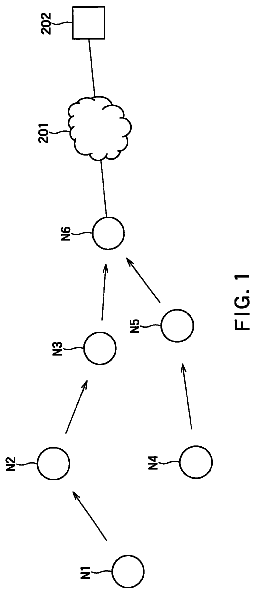
1 of 16 drawing sheets so far from the published document, cropped to the drawing. Every sheet is in the USPTO PDF.
What the patent claimed, word for word. All of it is now free to use.
The present disclosure relates to routing in wireless networks and, in particular, to distributed routing in multi-hop wireless networks using more than one route metric.
Dense deployment of base stations or wireless access nodes may be used to address the exponential growth in wireless data traffic. The feasibility of a dense deployment of wireless access nodes is predicated on the existence of a backhaul network that can provide high data rate transport for each individual access node in the network. From the point of view of maximizing capacity, optical fiber based backhaul solutions are desirable and are suitable for new constructions. However, in existing buildings and infrastructure, the cost of installing new fibers to every access node in a very dense network can be prohibitive.
An alternative to the optical backhaul solution is the wireless self-backhaul solution, where the same access spectrum is used to provide transport. With self-backhauling, an access node serves not only its own assigned User Equipment (UE) in its vicinity but also its neighboring access nodes as a relaying node in order to route data towards and/or from an information aggregation node in the network. A group of self-backhauling access nodes can form a multi-hop mesh network. Access nodes cooperatively route each other's traffic to and from the aggregation node.
Finding an optimal (or close to optimal) route from a source node to a destination node in a multi-hop network often is formulated in terms of finding a route that maximizes or minimizes the value of a single route metric. The route metric may be, for example, route bit rate capacity, route power consumption, route latency, etc. If the route metric is simple enough—that is, if it is both monotonic and isotonic—there exist efficient polynomial-time algorithms for finding the optimal route, e.g., the Bellman-Ford algorithm and the Dijkstra algorithm. In the general case, however, the problem is Non-Deterministic Polynomial-Time hard (NP-hard), i.e., the computational complexity grows exponentially with the number of nodes.
Unfortunately, in practice, the desire to take multiple route properties into account in the route metric (e.g., both route bit rate and route latency) makes it difficult to formulate an appropriate route metric that is simple enough (i.e., is both monotonic and isotonic) to be used with existing polynomial-time algorithms (e.g., the Bellman-Ford algorithm and the Dijkstra algorithm) for finding the optimal route through a multi-hop wireless network. As such, finding optimal routes for a route metric that takes multiple route properties into account may be computationally unfeasible using known algorithms. As such, there is a need for systems and methods for finding an optimal, or close to optimal, route from a source node to a destination node in a multi-hop network when taking multiple route properties into consideration.
Systems and methods related to distributed route determination through a multi-hop wireless network based on multiple route metrics or properties are disclosed. In some embodiments, a method of operation of a network node in a wireless network to provide distributed multi-hop route determination comprises identifying, by the network node, a subset of neighbors of the network node in the wireless network based on: (a) link weight(s) for links from the network node to at least some of the neighbors of the network node with respect to route metric(s) for a multi-hop route through the wireless network and (b) defined limit(s) for the route metric(s). In some embodiments, the subset of the neighbors of the network node are neighbors determined to satisfy the limit(s) on the route metric(s) based on the link weights with respect to the route metric(s). The method further comprises obtaining, by the network node, second link weights for the links from the network node to at least the subset of the neighbors with respect to a second route metric for a multi-hop route through the wireless network, and identifying, by the network node, from the subset of the neighbors, an optimal next hop neighbor for the network node in a multi-hop route through the wireless network based on the second link weights. In this manner, multiple route metrics are taken into consideration when identifying the optimal route from the source node to the destination node through the multi-hop wireless network in manner that is computationally efficient.
In some embodiments, identifying the subset of the neighbors of the network node comprises, based on the link weights for the links from the network node to at least some of the neighbors of the network node with respect to the route metric(s), removing the neighbor(s) of the network node that do not satisfy the defined limit(s) for the route metric(s) from a neighbor list of the network node to provide a trimmed neighbor list of the network node. This trimmed neighbor list is a list of neighbors for consideration with respect to the second route metric such that the neighbors in the trimmed neighbor list form the subset of the neighbors of the network node that are to be considered when identifying the optimal next hop neighbor based on the second route metric. Identifying the optimal next hop neighbor comprises identifying one of the subset of the neighbors of the network node in the trimmed neighbor list as the optimal next hop neighbor based on the second link weights.
In other embodiments, obtaining the second link weights comprises obtaining the second link weights for the links from the network node to the neighbors with respect to the second route metric. Identifying the optimal next hop neighbor for the network node then comprises penalizing the second link weights of the neighbors of the network node that are not in the subset of neighbors of the network node and, after penalizing the second link weights of the neighbors of the network node that are not in the subset of the neighbors of the network node, identifying one of the neighbors of the network node as the optimal next hop neighbor based on the second link weights.
In some embodiments, the route metric(s) consist of a first route metric (μ.sub.A) such that identifying the subset of the neighbors comprises obtaining, for each neighbor, a first link weight for the link from the network node to the neighbor with respect to the first route metric (μ.sub.A) and identifying the subset of the neighbors that satisfy a defined limit for the first route metric (μ.sub.A) based on the first link weights for the links from the network node to the neighbors of the network node.
In some embodiments, the method of operation of the network node further comprises identifying a second subset of the neighbors of the network node that satisfy a defined limit for the second route metric (μ.sub.B) based on the second link weights, and identifying, from the second subset of the neighbors, a second optimal next hop neighbor for the network node in a multi-hop route through the wireless network based on the first link weights for the links from the network node to at least the subset of the neighbors with respect to the first route metric (μ.sub.A).
In some embodiments, the second route metric (μ.sub.B) is an individual route metric. In some embodiments, a composite route metric of the first route metric (μ.sub.A) and the second route metric (μ.sub.B) is non-isotonic. In some embodiments, the first route metric (μ.sub.A) and the second route metric (μ.sub.B) are both monotonic and isotonic.
In some embodiments, identifying the optimal next hop neighbor for the network node comprises identifying one of the plurality of neighbors of the network node as the optimal next hop neighbor for the network node based on a composite route metric (μ.sub.composite) that is a function of the first route metric (μ.sub.A), the second route metric (μ.sub.B), and a penalty function that penalizes the second route metric (μ.sub.B) if the first route metric does not satisfy the defined limit on the first route metric (μ.sub.A). In some embodiments, the composite route metric (μ.sub.composite) is non-isotonic.
In some embodiments, the first route metric (μ.sub.A) is one of a maximum or minimum metric, and the second route metric (μ.sub.B) is an additive metric.
In some embodiments, the one or more route metrics comprise a first route metric (μ.sub.A) and an additional route metric such that identifying the subset of the neighbors comprises: (a) obtaining, for each neighbor of the network node, a first link weight for the link from the network node to the neighbor with respect to the first route metric (μ.sub.A); (b) identifying a first subset of the neighbors that satisfy a defined limit for the first route metric (μ.sub.A) based on the first link weights for the links from the network node to the neighbors of the network node; (c) obtaining, for each neighbor of the network node in at least the first subset of the neighbors, an additional link weight for the link from the network node to the neighbor with respect to the additional route metric; and (d) identifying, from the first subset of the neighbors, a second subset of the neighbors of the network node that satisfy a defined limit for the additional route metric based on the additional link weights for the links from the network node to at least the first subset of the neighbors of the network node.
In some embodiments, the method of operation of the network node further comprises receiving, by the network node, an updated limit for at least one of the one or more route metrics. The method of operation of the network node further comprises identifying a new subset of the neighbors of the network node based on the updated limit for the at least one of the one or more route metrics, and identifying, from the new subset of the neighbors of the network node, a new optimal next hop neighbor for the network node in a multi-hop route through the wireless network with respect to the second route metric.
In some embodiments, the method of operation of the network node further comprises receiving, by the network node, the one or more defined limits for the one or more route metrics. Further, in some embodiments, the method of operation of the network node comprises providing the one or more defined limits for the one or more route metrics to at least one of the neighbors of the network node in the wireless network. In other embodiments, the method of operation of the network node further comprises providing the one or more defined limits for the one or more route metrics to each of the neighbors of the network node in the wireless network.
Embodiments of a network node that operates to provide distributed route determination according to any of the processes disclosed herein are also disclosed.
Embodiments of a method of operation of a wireless network are also disclosed. In some embodiments, the method comprises: (a) finding, by the wireless network in a distributed manner, a route from a source node to a destination node through the wireless network according to a first route metric (μ.sub.A); (b) establishing, by a source node, a limit on the first route metric (μ.sub.A) for the route based on a weight assigned to the route from the source node to the destination node for the first route metric (μ.sub.A); (c) providing the limit on the first route metric (μ.sub.A) from the source node to at least some of a plurality of network nodes in the wireless network; (d) trimming, by each network node, links with neighbor nodes for which the limit on the first route metric (μ.sub.A) is not satisfied from consideration for an optimal route from the source node to the destination node according to a second route metric (μ.sub.B) to thereby provide a trimmed network; and (e) finding, by the wireless network in a distributed manner, an optimal route from the source node to the destination node through the trimmed network according to the second route metric (μ.sub.B).
In some embodiments, trimming the links with the neighbor nodes for which the limit on the first route metric (μ.sub.A) is not satisfied comprises removing the links with the neighbor nodes for which the limit on the first route metric (μ.sub.A) is not satisfied from consideration for the optimal route from the source node to the destination node according to the second route metric (μ.sub.B).
In some embodiments, trimming the links with the neighbor nodes for which the limit on the first route metric (μ.sub.A) is not satisfied comprises penalizing, with respect to the second route metric (μ.sub.B) the links with the neighbor nodes for which the limit on the first route metric (μ.sub.A) is not satisfied such that the links with the neighbor nodes for which the limit on the first route metric (μ.sub.A) is not satisfied are effectively removed from consideration for the optimal route from the source node to the destination node according to the second route metric (μ.sub.B).
In some embodiments, finding the route from the source node to the destination node through the wireless network according to the first route metric (μ.sub.A) comprises finding an optimal route from the source node to the destination node through the wireless network according to the first route metric (μ.sub.A).
In some embodiments, finding the route from the source node to the destination node through the wireless network according to the first route metric (μ.sub.A) comprises finding a route from the source node to the destination node through the wireless network having a weight for the first route metric (μ.sub.A) that is better than a predefined threshold.
In some embodiments, the method of operation of the wireless network further comprises determining whether a weight of the optimal route for the second route metric (μ.sub.B) is better than a predefined acceptable level. The method further comprises, if the weight of the optimal route for the second route metric (μ.sub.B) is not better than the predefined acceptable level: (a) establishing, by the source node, a new limit on the first route metric (μ.sub.A) for the route that is less restrictive than the limit on the first route metric (μ.sub.A); (b) providing the new limit on the first route metric (μ.sub.A) from the source node to at least some of the plurality of network nodes in the wireless network; (c) removing, by each network node in the plurality of network nodes, all links with neighbor nodes for which the new limit in the first route metric (μ.sub.A) is not satisfied from consideration for a new optimal route from the source node to the destination node according to the second route metric (μ.sub.B) to thereby provide a new trimmed network; and (d) finding, by the wireless network in a distributed manner, a new optimal route from the source node to the destination node through the new trimmed network according to the second route metric (μ.sub.B).
In some embodiments, the method of operation of the wireless network further comprises: (a) finding, by the wireless network in a distributed manner, a route from the source node to the destination node through the wireless network according to the second route metric (μ.sub.B); (b) establishing, by the source node, a limit on the second route metric (μ.sub.B) for the route based on a weight assigned to the route from the source node to the destination node for the second route metric (μ.sub.B); (c) providing the limit on the second route metric (μ.sub.B) from the source node to at least some of the plurality of network nodes in the wireless network; (d) removing, by each network node in the plurality of network nodes, all links with neighbor nodes for which the limit on the second route metric (μ.sub.B) is not satisfied from consideration for an optimal route from the source node to the destination node according to the first route metric (μ.sub.A) to thereby provide a second trimmed network; (e) finding, by the wireless network in a distributed manner, an optimal route from the source node to the destination node through the second trimmed network according to the first route metric (μ.sub.A); and (f) selecting one of the optimal route from the source node to the destination node through the trimmed network according to the second route metric (μ.sub.B) and the optimal route from the source node to the destination node through the second trimmed network according to the first route metric (μ.sub.A) as a best optimal route.
In some embodiments, the method of operation of the wireless network further comprises, prior to finding the optimal route from the source node to the destination node through the trimmed network according to the second route metric (μ.sub.B), further trimming the trimmed network based on one or more additional route metrics and one or more defined limits for the one or more additional route metrics.
Those skilled in the art will appreciate the scope of the present disclosure and realize additional aspects thereof after reading the following detailed description of the embodiments in association with the accompanying drawing figures.
The accompanying drawing figures incorporated in and forming a part of this specification illustrate several aspects of the disclosure, and together with the description serve to explain the principles of the disclosure.
FIG. 1 illustrates a directed graph that represents a multi-hop wireless network that includes a number of network nodes represented as vertices in the directed graph and (potential) wireless links between the network nodes represented by edges between the vertices;
FIG. 2 is an illustration of the concept of isotonicity;
FIG. 3 illustrates one example of a wireless network that performs distributed route determination according to some embodiments of the present disclosure;
FIG. 4 is a generalized block diagram of a wireless network (e.g., the wireless network of FIG. 3 ) that includes a number of network nodes and links between the network nodes according to one example of a wireless network;
FIG. 5 illustrates a process for finding an optimal route from a source node to a destination node in a wireless network according to some embodiments of the present disclosure;
FIG. 6 illustrates an example process flow for identifying an optimal route through a wireless network based on more than one route metric in which the process may be iteratively repeated until the optimal route is acceptable in accordance with some other embodiments of the present disclosure;
FIG. 7 illustrates an example process flow for identifying an optimal route through a wireless network based on more than one route metric in accordance with some other embodiments of the present disclosure;
FIG. 8 illustrates an example process flow for identifying an optimal route through a wireless network based on more than one route metric in which the ordering of the route metrics is swapped in accordance with some other embodiments of the present disclosure;
FIG. 9 illustrates an example process flow for identifying an optimal route through a wireless network based on more than one route metric in accordance with some other embodiments of the present disclosure;
FIG. 10 illustrates the operation of a network node to enable distributed route determination based on more than one route metric in accordance with some embodiments of the present disclosure;
FIG. 11 illustrates the operation of a network node to enable distributed route determination based on more than one route metric in accordance with some other embodiments of the present disclosure;
FIGS. 12A and 12B illustrate the operation of a network node to enable distributed route determination based on more than one route metric in which trimming of the network is performed by removing neighbors from a neighbor list of the network node in accordance with some other embodiments of the present disclosure;
FIGS. 13A and 13B illustrate the operation of a network node to enable distributed route determination based on more than one route metric in which trimming of the network is performed by penalizing link weights in accordance with some other embodiments of the present disclosure;
FIG. 14 is a block diagram of a network node according to some embodiments of the present disclosure; and
FIG. 15 is a block diagram of a network node according to some other embodiments of the present disclosure.
The embodiments set forth below represent information to enable those skilled in the art to practice the embodiments and illustrate the best mode of practicing the embodiments. Upon reading the following description in light of the accompanying drawing figures, those skilled in the art will understand the concepts of the disclosure and will recognize applications of these concepts not particularly addressed herein. It should be understood that these concepts and applications fall within the scope of the disclosure and the accompanying claims.
Systems and methods are disclosed for distributed routing through a multi-hop wireless network. Before describing these embodiments, a discussion of a multi-hop network and terminology that will be used throughout this disclosure is beneficial. FIG. 1 illustrates a directed graph that represents a multi-hop wireless network that includes a number of network nodes represented as vertices in the directed graph and (potential) wireless links between the network nodes represented by edges between the vertices. Specifically, the multi-hop network can be modelled as a directed graph G≡(V,E), where V denotes the set of graph vertices, and E denotes the set of edges. Each network node is then represented by a graph vertex vεV, and each (potential) wireless link between two network nodes is represented by an edge eεE. A route from a source node (e.g., a mesh network egress point) to a destination node (e.g., a user terminal) can be represented by a path P in the wireless network, which is a sequence of vertices {v.sub.i}.sub.i=1.sup.K such that v.sub.iεV for all i and (v.sub.i,v.sub.i+1)εE for all i=1, 2, . . . , K−1, where K denotes the number of vertices on the path P, v.sub.1 is the start vertex, and v.sub.K is the end vertex. In the example shown in FIG. 1 , v.sub.1 is vertex A and v.sub.K is vertex B. For any given path P, define E(P) as the set of all edges {(v.sub.i,v.sub.i+1)}.sub.i=1.sup.K−1 formed by adjacent vertices on the path P. In FIG. 1 , P={(A, B),(B, C)}. The term subpath may be used to refer to a contiguous set of edges along a given path. For example, in FIG. 1 , {(A, B)} forms a subpath of P. For simplicity, vertices and edges will henceforth often (somewhat informally) be referred to as “nodes” (or “network nodes”) and “links”.
Routing through the wireless network is often performed by first defining a route metric μ. The route metric μ in principle assigns a weight w.sub.μ(P) to each possible path or subpath (denoted together as (sub)path) P in the wireless network. In many cases, it is possible to express the (sub)path weight w.sub.μ(P) as a function of individual link weights w.sub.μ(l) for lεE(P). Additive metrics can be defined as the sum of individual link weights w.sub.μ(l). For example, the latency w.sub.latency(P) of a path P is the sum of the latencies w.sub.latency(l) of the individual links:
w latency ( P ) = .Math. l ∈ E ( P ) w latency ( l ) . ( 1 ) Minimum (or maximum) route metrics are the minimum (or maximum) of the individual link weights. For example, the bit rate w.sub.bitrate(P) of a path P is the minimum (bottleneck) bit rate w.sub.latency(l) of the links along the path P: w .sub.bitrate( P )=min.sub.lεE(P) w .sub.bitrate( l ).
Depending on the metric type, the path weight should either be minimized or maximized. For example, the latency should be minimized, whereas the bit rate should be maximized. It is, however, convenient to consistently use metrics of one of the two types. This can be achieved by converting route metrics of the other type to the desired type. For example, instead of bit rate (which should be maximized), one may use the inverse of the bit rate (which should be minimized). We will henceforth assume that weights should always be minimized.
Once the route metric is defined, the route that optimizes the route metric should be found. If the route metric is monotonic and isotonic, there are efficient algorithms for finding the optimal route. As used herein, “monotonicity” means that if a path is extended by one more link at either end, the weight of this extended path is at least as large as the weight of the original path. Hence, given a monotonic route metric μ, if any path P is extended by one link (v.sub.K,v.sub.K+1), where v.sub.K denotes the end vertex of the path P, to form an extended path P′={P,v.sub.K+1}, then it holds that w.sub.μ(P′)≧w.sub.μ(P).
As used herein, “isotonicity” means that the route metric preserves the ordering of the weights of two paths when they are extended by a common third link or set of links. Hence, given an isotonic route metric μ, if any two paths P.sub.1 and P.sub.2 that share the same source and destination vertices are extended by a common link (v.sub.K,v.sub.K+1), where v.sub.K is the end vertex of both P.sub.1 and P.sub.2, to form extended paths P′.sub.1={P.sub.1,v.sub.K+1} and P′.sub.2{P.sub.2,v.sub.K+1}, then it holds that w.sub.μ(P.sub.1)≧w.sub.μ(P.sub.2) implies w.sub.μ(P′.sub.1)≧w.sub.μ(P′.sub.2) (and vice versa). FIG. 2 is an illustration of the concept of isotonicity. If the route metric is isotonic, then the ordering of the two paths from A to B (i.e., which of the solid and the dashed paths has the lowest metric) is guaranteed to be unaltered when the two paths are extended with an additional common link (B to C).
It may be noted that if the path weights can be expressed as a sum or maximum/minimum of independent and positive constituent link weights (i.e., weights that are independent of what other links are used), the route metric will automatically be monotonic and isotonic. However, in a wireless network with interference between links, the weights of existing links will typically change as more links are added to a path, and isotonicity will normally be broken.
Routing can either be centralized (i.e., one central node takes the routing decision) or distributed (i.e., network nodes may take routing decisions locally). Distributed routing can be either source-oriented (i.e., finding a route to reach the source node) or destination-oriented (i.e., finding a route to reach the destination node). Distributed routing generally includes the following main steps: (i) collecting relevant information at each network node about the quality of potential links with its neighbor nodes; (ii) selecting the next hop neighbor at each node based on the collected information in order to reach the source (or, respectively, the destination) with the best resulting route metric; and (iii) communicating information about which neighbor nodes of each network node are on the selected path (e.g., in case of source-oriented routing in order to reach the destination in the reverse direction). With distributed routing, it is not necessary for any network node in the network to have a global knowledge about the topology of the network or the final selected path/route. Every network node only needs to know the neighbor to which the network node is to forward packets. The embodiments described herein generally focus on step (ii) where the selection of the next hop neighbor at each network node is performed in a distributed fashion without the need of a centralized entity in the network. For simplicity of discussion, we assume destination-oriented routing in the following discussion, while noting that the embodiments disclosed herein apply equally well to source-oriented routing.
Systems and methods are disclosed herein to (i) provide a way to combine two (or possibly more) different route metrics into a sensible composite route metric and (ii) efficiently find a route that optimizes this metric in a distributed manner, even though, in some embodiments, the metric may be non-isotonic.
To simplify the presentation, an example embodiment for a special case of two individual metrics being bit rate and power consumption is first described. The more general case is described below.
The basic idea is to define, as an optimal route, a route that has as low as possible power consumption while still reaching at least a certain predefined fraction k (e.g., 95%) of the maximum possible bit rate that would be attainable if the power consumption were not considered. In other words, one primarily attempts to reach as high bit rate as possible, but is willing to sacrifice some of the bit rate ( 1 - k , e.g., 5%) in order to reduce power consumption. With such a composite route metric (precise composite route metric definition is provided below), the optimal route can be found in three steps.
In the first step, the (optimal or best) next hop node of each network node is found for the highest bit rate route without considering power consumption. The source node (or the destination node in source-oriented routing) also determines the corresponding highest bit rate achieved by the resulting optimal route for the highest bit rate. Since the bit rate metric is monotonic and isotonic, algorithms, such as Bellman-Ford, can be used to identify the (optimal or best) next hop node of each network node, and hence the corresponding optimal route in a distributed fashion. Let R.sub.max denote the maximum bit rate.
In the second step, the source node (or the destination node in source-oriented routing) floods the network with information about the maximum bit rate R.sub.max, and possibly a predefined fraction k (which is information indicative of a predefined limit on the route metric, which in this case is the maximum bit rate R.sub.max) to every network node, or at least some of the network nodes, in the network.
In the third step, each network node starts anew, this time first removing all links with neighboring nodes with maximum possible bit rate over the link below kR.sub.max. The resulting trimmed network can easily be shown to still allow all routes with bottleneck bit rates larger than or equal to kR.sub.max, but no other routes. In this trimmed network, the route with the lowest power consumption is then sought in a distributed manner based on the power consumption metric. Since the power consumption metric is isotonic, that route can be efficiently found using, for example, the Bellman-Ford algorithm.
On a high level, embodiments are disclosed for: (i) combining two (or possibly more) different link weights into a composite link weight, from which a composite route, or path, metric can be defined and (ii) computationally efficiently (in polynomial time) finding a route that optimizes this composite route metric in a distributed manner, even though the composite route metric may be non-isotonic.
In particular, let w.sub.μ.sub. A (l) and w.sub.μ.sub. B (l) be the weights of a link lεE in the network for two route metrics μ.sub.A and μ.sub.B, respectively. In other words, the metrics of any path P are obtained by combining the corresponding weights of links lεE(P) over the path P. According to a preferred embodiment, the first route metric μ.sub.A of a path P is a minimum metric or a maximum metric that combines the link weights according to: w .sub.μ.sub. A ( P )≡min.sub.lεE(P) w .sub.μ.sub. A ( l )
or w .sub.μ.sub. A ( P )≡max.sub.lεE(P) w .sub.μ.sub. A ( l )
while the second route metric μ.sub.B is an additive metric that combines the link weights according to:
w μ B ( P ) ≡ .Math. l ∈ E ( P ) w μ B ( l ) . ( 5 ) The method for combining two link weights is, in its most simple incarnation, as follows. The weight of a link lεE(P) of a composite route metric, μ.sub.composite, is defined by ascribing to each link lεE(P) a composite link weight w .sub.composite( l )= w .sub.μ.sub. B ( l )+ T ( w .sub.μ.sub. A ( l )− C ( s,d ))
where C(s,d)=ƒ′(min.sub.P′εP(s,d)w.sub.μ.sub. A (P′)) is a threshold expressed via a predefined function ƒ′, T(•) is a predefined penalty function, s is the source vertex of P, d is the destination vertex of P, and P(s,d) is the set of all paths from s to d in the network.
One example of the penalty function T(•) is the “infinite brick wall” function given by:
T ( x ) = { + ∞ if x > 0 0 otherwise ( 7 ) For this penalty function, expressed in words, the resulting weight w.sub.composite(l) of a link according to the composite route metric μ.sub.composite is: +∞ if the link weight w.sub.μ.sub. A (l) for the first route metric μ.sub.A is above a certain threshold C(s,d), where the threshold C(s,d) is a predefined function ƒ′ of the lowest route, or path, weight w.sub.μ.sub. A (P′) of any path P′εP(s,d) from the source vertex to the destination vertex, otherwise the link weight w.sub.μ.sub. B (l) of the link for the second route metric μ.sub.B.
Other examples of the penalty function T(•) include an exponential function given by
T(x)=ae.sup.bx, for some constant a>0 and b>0,
a sigmoid function such as
T ( x ) = ax 1 + x 2 , for some large constant a>0 or a linear function given by
T(x)=ax, for some constant a>0.
These functions can be viewed as approximations of the “infinite brick wall” function in Equation
that can be used to impose soft penalty on links based on their link weights (according to the first route metric μ.sub.A) with respect to the threshold C(s,d). Using the infinite brick wall function (or an approximation thereof), in the composite link weight w.sub.composite(l) of Equation (6), the link metric w.sub.μ.sub. B (l) is penalized, according to the penalty function T(•), if the link weight w.sub.μ.sub. A (l) is not greater than the threshold C(s,d).
According to one preferred embodiment, the route, or path, metric of a given path P may be defined as an additive metric with respect to the composite link weight w.sub.composite(l) as follows:
w μ composite ( P ) = .Math. l ∈ E ( P ) w μ composite ( l ) . ( 8 ) Such a composite route metric is guaranteed to be isotonic. It should be noted that the composite route metric μ.sub.composite defined here is not only a function of the individual route metrics μ.sub.A and μ.sub.B for the path P (or the composite link weight w.sub.composite(l) according to the composite route metric μ.sub.composite is not only a function of the individual link weights w.sub.μ.sub. A (l) and w.sub.μ.sub. B (l)), but also considers information about other paths P′ in the network in a specific way.
The formation of the composite route metric μ.sub.composite can be generalized in several ways. Some generalizations will be implicitly defined from the following description of embodiments for finding the optimal route from two or more route metrics.
Note that one way to interpret such a composite route metric is to search for the optimal route(s) according to the first route metric μ.sub.A, trim the connection graph to keep only those network nodes that are good enough to be within a tolerance of the optimal metric with respect to the first route metric μ.sub.A, and then search for the optimal route(s) with respective to the second route metric μ.sub.B on the trimmed connection graph. The resulting route(s) found in such a manner is/are guaranteed to perform well with respect to both the first and second route metrics μ.sub.A and μ.sub.B, while both search steps involve only isotonic metrics and can therefore employ any existing, efficient distributed routing algorithm. Trimming the connection graph (which is also referred to herein as trimming the network or trimming the neighbor lists of the network nodes) may include updating a neighbor list of each (or at least some) network node by removing entries to neighboring nodes. In other embodiments, the neighbor lists are not actually trimmed; rather, the weights with respect to the second route metric μ.sub.B of the links to neighbors that do not satisfy the tolerance of the optimal metric with respect to the first route metric μ.sub.A are penalized to effectively remove those neighbors from consideration for the optimal route (i.e., to effectively trim the network).
Before describing embodiments of the present disclosure, it may be beneficial to first describe one example of a wireless network 10 , as illustrated in FIG. 3 , that may utilize the embodiments described herein to find a route (e.g., a best or optimal route) from a source node to a destination node when taking multiple route properties, or multiple route metrics, into consideration according to some embodiments of the present disclosure. While not being limited to any particular type of wireless network, in this example, the wireless network 10 includes a number of wireless access nodes (ANs) 12 - 1 through 12 - 3 (generally referred to herein collectively as access nodes 12 and individually as access node 12 ) providing access to a cellular communications network to a number of wireless devices 14 - 1 and 14 - 2 (generally referred to herein collectively as wireless devices 14 and individually as wireless device 14 ). The access nodes 12 form a wireless mesh network for backhaul transport to, e.g., a core network of the cellular communications network via an aggregation node 16 . The access nodes 12 , the wireless devices 14 , and the aggregation node 16 are all network nodes in the wireless network 10 . The systems and methods disclosed herein may be utilized to, e.g., find optimal routes from, e.g., the aggregation node 16 to each of the other network nodes in the wireless network 10 and/or to find optimal routes from each of the network nodes 12 , 14 to the aggregation node 16 taking into account multiple route properties/metrics.
FIG. 4 is a generalized diagram of a wireless network (e.g., the wireless network 10 of FIG. 3 ). As illustrated, the wireless network includes a number of network nodes (NNs) and (potential) wireless links (l) between the network nodes. Each link is from a transmitter of one network node to a receiver of another network node. So, for instance, link l.sub.12 is the link from the transmitter of network node NN 1 to the receiver of network node NN 2. In this context, a neighboring network node of, e.g., the network node NN 1 is another network node with which the network node NN 1 is capable of establishing a wireless link (l). So, in this example, network nodes NN 2, NN 3, and NN 4 are neighbors of the network node NN 1.
FIG. 5 illustrates a process for finding an optimal route from a source node to a destination node in a wireless network (e.g., the wireless network 10 of FIG. 3 ) according to some embodiments of the present disclosure. Notably, for all process figures illustrated and described herein, the “steps” may be performed in any suitable order and even in parallel unless otherwise required. In general, FIG. 5 illustrates a process for finding the optimal route (i.e., an optimal path from a source node to a destination node) through a wireless network (e.g., the wireless network 10 of FIG. 3 ) in accordance with a composite route metric μ.sub.composite defined as above. In this example, the composite route metric μ.sub.composite is the composite of a first route metric μ.sub.A and a second route metric μ.sub.B, and includes a penalty function that effectively penalizes the second route metric μ.sub.B if the first route metric μ.sub.A does not satisfy a predefined limit.
The description continues in the full USPTO document.
About 6,597 words. The USPTO PDF has it with every drawing.
Fees are due 3.5, 7.5 and 11.5 years after grant. This patent expired on August 8, 2025, so the fee marked "not paid" was the one that went unpaid.
DISTRIBUTED ROUTING IN WIRELESS NETWORKS
Filed Nov 2014 · published May 2015Distributed routing in wireless networks
Filed Nov 2014 · granted Aug 2017Earlier publications, parents and continuations. None of them can still be enforced, or this patent would not be listed.
Prior art cited by the examiner or applicant. Useful when you check your own idea for novelty.
Everything on this page comes from the documents linked above.