Technical field
The present invention relates to an imaging device and a defective pixel correction method.
Background art
In recent years, solid-state imaging devices have been progressing toward a great number of pixels and a narrow pixel pitch, and color mixture or pixel defect that may accordingly occur has a big effect on an image quality.
Defective pixel corrections are generally performed by replacing a signal obtained from a defective pixel with a mean value of signals obtained from the pixels which have the same color as the defective pixel, located around the defective pixel. However, according to the progress in realizing the number of pixels and the narrow pixel pitch, such a general correction method may cause a scar of the correction to be conspicuous. This reason will be described in the following.
FIG. 13 is a diagram showing a pixel arrangement of a solid-state imaging element equipped with a color filter with Bayer pattern. In FIG. 13 , the blocks marked with “R” denote R pixels for detecting red light, the blocks marked with “B” denote B pixels for detecting blue light, the blocks marked with “Gr” denote that there are R pixels at left and right sides thereof among G pixels detecting green light, and the blocks marked with “GB” denote that there are B pixels at left and right sides thereof among G pixels detecting green light.
As shown in FIG. 13 , in the solid-state imaging element equipped with the color filter of Bayer pattern, the solid-state imaging element includes three types of R pixel, G pixel, and B pixel. The G pixel among the three types of pixels may be divided into two kinds of attributes (Gr pixel, Gb pixel) around which R pixel and B pixel are differently arranged.
Since the Gb pixel and Gr pixel each have a different arrangement of R pixel and B pixel at its adjacent periphery, a difference between a signal level of the Gr pixel and a signal level of the Gb pixel is generated by color mixture depending on the incidence direction of incident light. The larger the incidence angle of light to the solid-state imaging element is like light causing a ghost signal level and the closer to monochromatic light the incident light becomes like red light, the more prominent the difference in the signal level becomes.
Thus, for example, in the case where there is a defective pixel at a position of a Gr pixel (or Gb pixel), if the defective pixel is corrected using four Gb pixels (Gr pixel) which are adjacent to the defective pixel in a X shaped direction (located at an obliquely upper right side, obliquely lower right side, obliquely upper left side, and obliquely lower left side of the defective pixel), since corrections are performed using an output signal of the Gb pixel (Gr pixel) having a different level, it is difficult to have an output level of the defective pixel closer to an original level.
Therefore, it may consider that the defective pixel located at a position of Gb pixel (or Bb pixel) is corrected by using the four Gr pixels (Gb pixels) which are adjacent to the defective pixel in the cross direction thereof (adjacent at the upper and lower, and right and left sides of the defective pixel). However, in this correction method, since the corrections are performed using a signal of a pixel located far from the defective pixel as compared to the method of performing the correction using the four pixels adjacent to the defective pixel in the X-shaped direction, in a high-frequency image, it is difficult to have the output level of the defective pixel close to the original level thereof.
A method of correcting a signal of defective pixel by using signals of pixels surrounding the pixel is disclosed, for example, in the following Patent Documents 1 to 3.
Patent Document 1 discloses a correction method of a defective pixel in a solid-state imaging device equipped with a color filter having Bayer pattern, and the correction method is performed by selecting any one of a first correction processing for performing corrections using output signals of pixels having the same color as the corresponding defective pixel which are adjacent to the defective pixel in a cross direction thereof and a second correction processing for performing corrections using output signals pixels having the same color as the corresponding defective pixel that are adjacent to the defective pixel in a X-shaped direction thereof, based on the correlation between the output signal of the corresponding defective pixel and the output signals of the same colored pixels that are adjacent to the corresponding defective pixel.
Patent Document 2 discloses a method of correcting an output signal of a corresponding target pixel using output signals of the same color pixels that are adjacent to the correction target pixel in the cross direction of the correction target pixel.
Patent Document 3 discloses a method of correcting an output signal of a correction target pixel by using output signals of eight pixels adjacent to the correction target pixel Patent Document 1: Japanese Patent Application Publication No. 2010-068329A Patent Document 2: Japanese Patent Application Publication No. 2011-015157A Patent Document 3: Japanese Patent Application Publication No.
H07-336605A
Since the device described in Patent Document 1 is intended to select a correction method based on the correlation between the output signal of the defective pixel and the output signals of the pixels surrounding the defective pixel, there may be a case where the second correction processing is performed even for the high-frequency image, in this case, a scar of the correction to the high-frequency image is conspicuous.
The device described in Patent Document 2 is intended to perform only the processing for correcting the output signal of the corresponding correction target pixel using the output signals of the same color pixels that are adjacent to the correction target pixel in the cross direction of the correction target pixel, it is impossible to solve the problem that a scar of the correction to the high-frequency image is conspicuous.
Like the solid-state imaging device shown in FIG. 13 , in the case where the correction method described in Patent Document 3 is applied to the solid-state imaging element having a plurality of types of same-color pixels (Gr pixel, Gb pixel) around which pixels are arrayed differently, correction data are generated using the signals of different colors and a scar of the correction is thereby conspicuous after the correction of the defective pixel.
The present invention has been made in an effort to solve the problems, and an object of the present invention is to provide an imaging device and a defective pixel correction method capable of improving the accuracy of a defective pixel correction.
Summary
An imaging device according to the present invention includes a solid-state imaging element for color imaging that has at least a first pixel group including at least three types of pixels that are two-dimensionally arranged and different from each other in a detection wavelength range; and a defective pixel correction unit that performs a defective pixel correction to a captured image signal output from the solid-state imaging element, wherein one type of pixels out of the at least three types of pixels is divided into two kinds of attributes of pixels around which arrangements of pixels that are arranged at the periphery of the corresponding pixels and different in its type from the corresponding pixels are different from each other; in a case where a correction target pixel is any one of the two kinds of attributes of pixels, the defective pixel correction unit determines whether an edge portion of a subject is put on a pixel area which is centered on the correction target pixel and includes pixels of the same attribute and the same type as the correction target pixel, when it is determined that the edge portion is put on the pixels, it performs a first correction processing, and when it is determined that the edge portion is not put on the pixels, it performs a second correction processing; the first correction processing is a processing for correcting an output signal of the corresponding correction target pixel using output signals of the pixels in the first pixel group, which are of the different attribute while being of the same type as the corresponding correction target pixel and adjacent to the correction target pixel; and the second correction processing is a processing for correcting an output signal of the corresponding correction target pixel using output signals of the pixels in the first pixel group, which are of the same attribute while being of the same type as the corresponding correction target pixel and adjacent to the correction target pixel.
A defective pixel correction method of performing a defective pixel correction to a captured image signal output from a solid-state imaging element for color imaging that comprises at least a first pixel group comprising at least three types of pixels that are two-dimensionally arranged and different from each other in a detection wavelength range, wherein one type of pixels out of the at least three types of pixels is divided into two kinds of attributes of pixels around which arrangements of pixels that are arranged at the periphery of the corresponding pixels and different its type from the corresponding pixels are different from each other, the method comprises: an edge determination step of determining whether or not an edge portion of a subject is put on pixels of the first pixel group adjacent to a correction target pixel when the correction target pixel is any one of the two kinds of attributes of pixels; and a correction processing step of performing a first correction processing when it is determined that the edge portion is put on the pixels, and performing a second correction processing when it is determined that the edge portion is not put on the pixels, wherein the first correction processing is a processing for correcting an output signal of a corresponding correction target pixel using output signals of the pixels in the first pixel group, which are of the different attribute while being of the same type as the corresponding correction target pixel and adjacent to the correction target pixel, and the second correction processing is a processing for correcting an output signal of a corresponding correction target pixel by using output signals of the pixels in the first pixel group, which are of the same attribute while being of the same type as the corresponding correction target pixel and adjacent to the correction target pixel.
According to the present invention, it is possible to provide an imaging device and a defective pixel correction method which can improve the accuracy of defective pixel correction.
Brief description of drawings
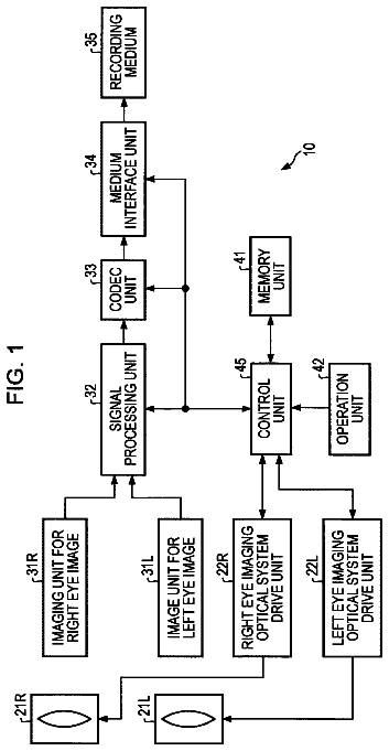
FIG. 1 is a schematic diagram showing a configuration of an imaging device according to an embodiment of the present invention.
FIG. 2 is a plan diagram showing a configuration of a solid-state imaging element 5 in a digital camera shown in FIG. 1 .
FIGS. 3A and 3B are diagrams illustrating a first correction processing and a second correction processing that a defective pixel correction unit 19 executes in the digital camera shown in FIG. 1 .
FIGS. 4A, 4B, 4C and 4D are diagrams illustrating an example of an edge determination processing that the defective pixel correction unit 19 executes in the digital camera shown in FIG. 1 .
FIG. 5 is a flowchart illustrating an operation of the defective pixel correction unit 19 in the digital camera shown in FIG. 1 .
FIG. 6 is a view illustrating a modification of the operation of the defective pixel correction unit 19 in the digital camera shown in FIG. 1 .
FIG. 7 is a flowchart illustrating a modification of the operation of the defective pixel correction unit 19 in the digital camera shown in FIG. 1 .
FIG. 8 is a schematic plan view showing a first modification of the solid-state imaging element 5 in the digital camera shown in FIG. 1 .
FIG. 9 is a schematic plan view showing a second modification of the solid-state imaging element 5 in the digital camera shown in FIG. 1 .
FIG. 10 is a schematic plan view showing a third modification of the solid-state imaging element 5 in the digital camera shown in FIG. 1 .
FIG. 11 is a schematic plan view showing a fourth modification of the solid-state imaging element 5 in the digital camera shown in FIG. 1 .
FIG. 12 is a schematic plan view showing a fifth modification of the solid-state imaging element 5 in the digital camera shown in FIG. 1 .
FIG. 13 is a view illustrating a pixel array of the solid-state imaging element equipped with a color filter with Bayer pattern.
Detailed description
Hereinafter, embodiments of the present invention will be described with reference to the accompanying drawings.
FIG. 1 is a diagram showing a schematic configuration of an imaging device according to one embodiment of the present invention. As an imaging device, there are an imaging device such as a digital video camera and a digital camera, an imaging module that is mounted in a mobile phone with a camera, an electronic endoscope, and the like. Here, the digital camera will be described as an example.
An imaging system of s digital camera shown in FIG. 1 includes a photographing lens 1 including a focus lens, a zoom lens and the like, a solid-state imaging element 5 for color imaging that is an image sensor of a MOS type or a CCD type, a diaphragm 2 which is provided there-between, an infrared cut filter 3 , and an optical low-pass filter 4 .
A system controller 11 for overall control of an electric control system of the digital camera serves to control a lens driving unit 8 to thereby control the position of the focus lens of the photographing lens 1 or the position of the zoom lens, or serves to control the amount opening of the diaphragm 2 via the diaphragm driving unit 9 to thereby adjust the exposure amount.
Further, the system controller 11 serves to drive the solid-state imaging element 5 via an imaging element driving unit 10 , and to output, as a captured image signal, a subject image captured through the photographing lens 1 . An instruction signal from a user is input to the system controller 11 through an operation unit 14 .
In addition, the electric control system of the digital camera is provided with an analog signal processing unit 6 connected to an output of the solid-state imaging element 5 to execute an analog signal processing such as a correlated double sampling processing or the like, and an A/D converting circuit 7 that converts a captured image signal outputted from the analog signal processing unit 6 to a digital signal, which are controlled by the system controller 11 .
Further, the electric control system of the digital camera includes a main memory 16 ; a memory control unit 15 connected to the main memory 16 ; a digital signal processing unit 17 that executes gamma correction operation, RGB/YC conversion processing and the like with respect to the captured image signal outputted from the A/D converting circuit 7 to thereby generate captured image data; an compression and extension processing unit 18 that compresses the captured image data generated from the digital signal processing unit 17 in a JPEG format or extends the compressed image data; a defective pixel correction unit 19 that performs a defective pixel correction with respect to the capture image signal outputted from the A/D converting circuit 7 , which will be described later; an external memory control unit 20 connected to a detachable recording medium 21 ; and a display control unit 22 connected to a liquid crystal display unit 23 mounted on the rear of the camera or the like. The memory control unit 15 , the digital signal processing unit 17 , the compression and extension processing unit 18 , the defective pixel correction unit 19 , the external memory control unit 20 and the display control unit 22 are interconnected by a control bus 24 and a data bus 25 and controlled by a command from the system control unit 11 .
FIG. 2 is a schematic plan view showing a configuration of the solid-state imaging element 5 in the digital camera shown in FIG. 1 .
The solid-state imaging element 5 is provided with a plurality of pixels 51 , 52 , 53 , 54 arranged in a two-dimensional shape in a row direction X and a column direction perpendicular to the row direction X (in a square lattice shape in the example of FIG. 2 ). Each pixel included in the solid-state imaging element 5 includes a photoelectric conversion element such as a photodiode, and a color filter provided above the photoelectric conversion element.
The plurality of pixels includes three kinds of pixels each having a different-wavelength detecting region, i.e., R pixel 51 detecting red light (marked with “R” in FIG. 2 ), B pixel 52 detecting blue light (marked with “B” in FIG. 2 ), and G pixel 53 , 54 detecting green light (marked with “Gr, Gb” in FIG. 2 ). These three kinds of pixels are arranged in a Bayer pattern.
The G pixels 53 , 54 are arranged in a checkered position among the plurality of pixels arranged in a square grid shape, the R pixels 51 are arranged in the odd rows in the other checkered position, and the B pixels 52 are arranged in the even rows. In other words, the plurality of pixels are arranged in such a manner that the rows where the R pixels 51 and G pixels 54 are arranged alternately in the row direction X and the rows where the G pixels 53 and B pixels 52 are arranged alternately in the row direction X are arranged alternately in the column direction Y. Further, the plurality of pixels shown in FIG. 2 is formed, as a unit pixel, with the four pixels (R pixel 51 , B pixel 52 , G pixels 53 , 54 ) arranged at the corner of the upper left side, in which the unit pixels are arranged in a square lattice pattern.
As shown in FIG. 2 , the G pixel for detecting green light is classified into two kinds of attributes of pixels (G pixel 53 , G pixel 54 ), each of which has a different arrangement of R pixel 51 and B pixel 53 at the periphery of the corresponding G pixel and is a different type of pixel from the corresponding G pixel.
Hereinafter, the G pixel 53 having B pixels 52 at left and right sides thereof is referred to as Gb pixel 53 , and the G pixel 54 having R pixels 51 at left and right sides thereof is referred to as Gr pixel 54 . In FIG. 2 , the Gb pixel 53 is marked with “Gb” and the Gr pixel 53 is marked with “Gr”.
The Gb pixel 53 and the Gr pixel 54 each have the different arrangement of the R pixel 51 and B pixel 52 at each periphery thereof. Therefore, when light is obliquely incident on the solid-state imaging element 5 , a level difference, which is caused by color mixture depending on the incident direction of the incident light, occurs between the output signal of the Gb pixel 53 and the output signal of the Gr pixel 54 .
Next, the function of the defective pixel correction unit 19 in the digital camera shown in FIG. 1 will be described.
The defective pixel correction unit 19 performs a defective pixel correction to captured image signals (a group of output signals of each of the pixels included in the solid-state imaging element 5 ) that are temporarily stored in the main memory 16 and outputted from the solid-state imaging element 5 . The defective pixel correction refers to a processing of correcting a signal outputted from a defective pixel out of all pixels included in the solid-state imaging element 5 by using signals outputted from the pixels which correspond to the same type of pixel as the corresponding defective pixel and positioned at the periphery of the corresponding defective pixel.
Address information of the defective pixel of the solid-state imaging element 5 and information indicating the type (detected color) of the corresponding defective pixel are stored in the main memory 16 of the digital camera at the time of shipment of the digital camera. Therefore, the defective pixel correction unit 19 is capable of identifying a pixel to be corrected (correction target pixel) using the information.
In addition, the address information of a defective pixel of the solid-state imaging element 5 and information indicating the type (detected color) of the corresponding defective pixel may be updated at any time if a defective pixel occurs after shipment of the digital camera. Accordingly, the defective pixel correction unit 19 is also able to correct the so-called subsequent scratch that occurs after shipment of the digital camera.
When the correction target pixel is a G pixel that corresponds to the pixel type that is classified into two kinds of attributes among the three types of pixels included in the solid-state imaging element 5 , the defective pixel correction unit 19 executes selectively) one of the first correction processing and the second correction processing, thereby correcting the output signal of the corresponding G pixel.
The first correction processing refers to a processing in which an output signal of a correction target pixel among the output signals forming captured image signals stored in the main memory 16 is corrected using output signals of the pixels which are adjacent to the corresponding correction target pixel while being of the same kind of pixel as the corresponding correction target pixel, and at the same time belongs to a different attribute from the corresponding correction target pixel.
The second correction processing refers to a processing in which an output signal of a correction target pixel is corrected using output signals of the pixels which are adjacent to the corresponding correction target pixel while being of the same type of pixel as the corresponding correction target pixel, and at the same time, of the same attribute as the corresponding correction target pixel.
FIGS. 3A and 3B are diagrams illustrating the first correction processing and the second correction processing that are executed by the first defective pixel correction unit 19 in the digital camera shown in FIG. 1 . FIG. 3A is a diagram illustrating the first correction processing and FIG. 3B is a diagram illustrating the second correction processing.
FIGS. 3A and 3B show a part (5 rows×5 columns) of the pixels of the solid-state imaging element 5 shown in FIG. 2 (reference numeral is omitted). Hereinafter, the Gr pixel (marked with the mark ◯) positioned in the middle among the 25 pixels shown in FIGS. 3A and 3B will be assumed as a correction target pixel.
In the first correction processing, the defective pixel correction unit 19 corrects an output signal of a subject Gr pixel, using output signals of the four Gb pixels (pixels hatched in FIG. 3A ) adjacent to the Gr pixel of the correction target pixel in a X shaped direction (lower right, upper right, lower left and upper left of the corresponding Gr pixel). For example, the correction is performed by replacing the output signal of Gr pixel marked with ◯ mark with a mean value of the output signals of the four Gb pixels hatched. In the configuration of the solid-state imaging element shown in FIG. 2 , since the first correction processing is performed using the pixels that are adjacent to the correction target pixel in a X-shaped direction and have the same color as the correction target pixel, in the following, the first correction processing may be called a X-character correction processing.
In the second correction processing, the defective pixel correction unit 19 corrects an output signal of the subject Gr pixel by using output signals of the four Gr pixels (pixels hatched in FIG. 3B ) adjacent to the Gr pixel of the correction target pixel in a cross direction (upper and lower, and left and right of the corresponding Gr pixel). For example, the correction is performed by replacing the output signal of Gr pixel marked with the mark ◯ with a mean value of the output signals of the four Gb pixels hatched. In the configuration of the solid-state imaging element shown in FIG. 2 , since the second correction processing is performed using the pixels that are adjacent to the correction target pixel in a cross direction and have the same color as the correction target pixel, in the following, the second correction processing may be called a cross correction processing.
When the G pixel is a correction target pixel, the X-character correction processing, as compared to the cross correction processing, executes a correction by using the output signals of the same color pixels positioned closely to the correction target pixel. Accordingly, a scar of the correction on a high-frequency image is less noticeable. However, since the correction is performed using output signals of the same color pixels (pixels each having a large difference in its output level) having a different attribute from the correction target pixel, the correction mark is conspicuous on the low-frequency image.
Meanwhile, the cross correction processing is to perform a correction using output signals of the same color pixels (pixels each having a low difference in its output level) of the same attribute as the correction target pixel. Accordingly, a scar of the correction to a low-frequency image is hardly noticeable. However, since the correction is performed using output signals of the same color pixels located far from the correction target pixel, a scar of the correction on a high-frequency image is conspicuous.
As such, if the G pixel in the solid-state imaging element 5 is a correction target pixel, the cross correction processing and the X character correction processing have merits and demerits, respectively. Therefore, in the case where the correction target pixel is a G pixel, the defective pixel correction unit 19 performs an edge determination processing to determine whether an edge portion of a subject is put on the pixels positioned at the periphery of the corresponding correction target pixel. When it is determined in the edge determination processing that the edge portion is put on the pixels, the first correction processing is performed ( FIG. 3A ). When it is determined in the edge determination processing that the edge portion is not put on the pixels, the second correction processing is performed ( FIG. 3B ).
Incidentally, in the case where the correction target pixel is the R pixel 51 or the B pixel 52 , the defective pixel correction unit 19 corrects the output signal of the correction target pixel by using the output signals of the four R pixels 51 (B pixel 52 ) that is close to the R pixel 51 (B pixel 52 ) of the correction target pixel in the cross direction and that is the same type as the corresponding correction target pixel.
In the edge determination processing, for example, as shown in FIGS. 3A and 3B , the pixel area (edge determination region), which is to be determined as to whether the edge portion is put on, is determined on the region where the pixels of 5×5=25 pieces centered on the correction target pixel are positioned. If the cross correction process is to be performed, since it is necessary to use the four pixels of the same attribute and the same type adjacent to the correction target pixel, an area where the corresponding four pixels are included is determined as the edge determination area.
In the following, an example of edge determination processing will be described.
FIGS. 4A, 4B, 4C and 4D are diagrams illustrating an example of the edge determination processing. In FIGS. 4A to 4D , the pixel of 5 rows×5 columns centered on the Gr pixel to be corrected are shown (reference numeral is omitted).
As shown in FIG. 4A , the defective pixel correction unit 19 classifies the six R-pixels included in the 25 pixels centered on the correction target pixel into the two R-pixels (R pixel surrounded by mark Δ in the figure) positioned in the same row as the correction target pixel and the other 4 R-pixels (R pixel surrounded by mark □ in the figure), and calculates one evaluation value using the output signals of the 6 R-pixels.
Further, as shown in FIG. 4B , the defective pixel correction unit 19 classifies the six B-pixels included in the 25 pixels centered on the correction target pixel into the two B-pixels (B pixel surrounded by mark Δ in the figure) positioned in the same row as the correction target pixel and the other 4 B-pixels (B pixel surrounded by mark □ in the figure), and calculates one evaluation value using the output signals of the 6 B-pixels 52 .
As shown in FIG. 4C , the defective pixel correction unit 19 classifies the six Gr-pixels which are positioned at the periphery of the correction target pixel and included in the 25 pixels centered on the correction target pixel into the two Gr-pixels (Gr pixel surrounded by mark Δ in the figure) positioned in the same row as the correction target pixel and the other 4 Gr-pixels (Gr pixel surrounded by mark □ in the figure), and calculates one evaluation value by using the output signals of the 6 Gr-pixels.
As shown in FIG. 4D , the defective pixel correction unit 19 classifies the six Gr-pixels that are adjacent to the correction target pixel and included in the 25 pixels centered on the correction target pixel into the two Gr-pixels (Gr pixel surrounded by mark Δ in the figure) positioned in the same column as the correction target pixel and the other 4 Gr-pixels (Gr pixel surrounded by mark □ in the figure), and calculates one evaluation value by using the output signals of the 6 Gr-pixels.
The defective pixel correction unit 19 calculates the evaluation value corresponding to each of the classifications shown in FIGS. 4A to 4D by the following equation
using the output signals of the pixels surrounded by the mark Δ (hereinafter referred to as Δ pixel signal) and the output signals of the pixels surrounded by the mark □ (hereinafter, referred to as □ pixel signal), as shown in FIGS. 4A to 4D . Evaluation value={|(average value of 2Δ pixel signals)−(average value of four □ pixel signals)|}/(average value of total 6 pixel signals of two Δ pixel signals and four □ pixel signals)
One evaluation value corresponding to each of FIGS. 4A to 4D is calculated by the operation using equation (1).
The defective pixel correction unit 19 compares each of the four evaluation values obtained by the operation with a threshold value, determines that the edge portion is put on the area where the 25 pixels are arranged if at least one evaluation value exceeds the threshold value, and determines that the edge portion is not put on the area where the 25 pixels are arranged if at least one evaluation value does not exceed the threshold value.
Further, in the case where the correction target pixel is the Gb pixel, the evaluation value is obtained by the equation
by replacing “Gr” with “Gb” in FIGS. 4A to 4D , and the edge determination processing is thereby performed. The edge determination processing is not limited to the method described above, but well-known methods may be employed.
Next, the operation of the defective pixel correction unit 19 in the digital camera shown in FIG. 1 will be described.
FIG. 5 is a flowchart illustrating the operation of the defective pixel correction unit 19 in the digital camera shown in FIG. 1 .
An imaging process is performed by the solid-state imaging element 5 , and the captured image signal outputted from the solid-state imaging element in the imaging process is converted into a digital signal in the A/D converting circuit 7 , and then, stored temporarily in the main memory 16 .
While the captured image signal is stored in the main memory 16 , the defective pixel correction processing flow starts by the defective pixel correction unit 19 .
First, the defective pixel correction unit 19 reads, from the main memory 16 , the information (information on detected color) indicating the type of the defective pixel and the address information of the defective pixel included in the solid-state imaging element 5 (step S 1 ).
Next, the defective pixel correction unit 19 starts a processing loop for every defective pixel in step SA.
After start of the processing loop, the defective pixel correction unit 19 sets, as a correction target pixel, one defective pixel in accordance with the address information of the defective pixel, and determines whether the pixel set as a correction target pixel is a Gr pixel 54 or a Gb pixel 53 (step S 2 ).
The defective pixel correction unit 19 performs the processing in step S 3 when the pixel set as a correction target pixel is a Gr pixel 54 or Gb pixel 53 (step S 2 : YES), and performs the processing in step S 4 when the pixel set as a correction target pixel is a R pixel 51 or B pixel 52 (step S 2 : NO).
In step S 3 , the defective pixel correction unit 19 calculates four evaluation values as described above according to the equation (1).
In step S 4 , the defective pixel correction unit 19 corrects an output signal of the correction target pixel using the output signals of the four pixels that are of the same type as the correction target pixel and that are adjacent to the correction target pixel in the cross direction, and proceeds to step SB after the step S 4 .
In step SB, the defective pixel correction unit 19 determines whether a defective pixel correction has been made with respect to all defective pixels, but if a defective pixel having not been corrected exists, it sets the defective pixel as a correction target pixel to return to the processing in step S 2 , and if a defective pixel having not been corrected does not exist, it ends the defective pixel correction processing flow.
After step S 3 , the defective pixel correction unit 19 compares the four evaluation values calculated in step S 3 to the threshold value respectively step S 3 .
If no evaluation value exceeds the threshold value (step S 5 : NO), in this case, it may be determined that an edge portion of a subject is not put on a pixel positioned at the periphery of the correction target pixel (pixel at the periphery of the correction target pixel is overlapped with a low-frequency area of the subject). Accordingly, the defective pixel correction unit 19 performs the cross correction processing that is suitable for the low-frequency image (step S 6 ).
When there is an evaluation value exceeding the threshold value (step S 5 : YES), in this case, it may be determined that an edge portion of a subject is put on the pixel positioned at the periphery of the correction target pixel (pixel at the periphery of the correction target pixel is overlapped with a high-frequency area of the subject). Accordingly, the defective pixel correction unit 19 performs the X character correction processing suitable for a high-frequency image (step S 7 ).
As such, when the edge portion is overlapped with the pixels around the correction target pixel, since the output signal of the corresponding correction target pixel is corrected by the use of the output signals of the pixels of the same kind as the correction target pixel, which are at a position closer to the correction target pixel, the correction mark can be less conspicuous. In the area where the edge portion is overlapped, since the effect of level difference of the output signals of the Gb pixel and Gr pixel on the image quality is reduced, the X character correction processing is performed rather than the cross correction processing, thereby aiming at enhancement of image quality.
Further, when the edge portion is not overlapped with the pixels around the correction target pixel, since the output signal of the corresponding correction target pixel is corrected by the use of the output signals of the pixels of the same type and the same attribute as the correction target pixel, the correction mark can be inconspicuous. In the area where the edge portion is not overlapped, since the effect of level difference of the output signals of the Gr pixel and Gb pixel on the image quality is increased, the cross correction processing is performed rather than the X character correction processing, thereby aiming at enhancement of image quality.
As described above, in the case where the G pixel is a pixel to be corrected, the digital camera shown in FIG. 1 determines whether the edge portion of the subject is put on the pixels around the correction target pixel, when the edge portion is put thereon, it performs the X character correction processing, and when the edge portion is not put thereon, it performs the cross correction processing. As such, since it is possible to select and execute an optimal correction processing in accordance with the contents of the subject overlapped with the periphery area of the correction target pixel, it is possible to reduce the correction mark to a minimum after the defective pixel correction even with respect to a general subject in which a high-frequency area and a low-frequency area commonly exist and color mixing caused by ghost light source occurs, thereby improving image quality.
So far, it has been assumed that the 25 pixels centered on the correction target pixel do not include any defective pixel other than the corresponding correction target pixel. However, there may be even the case where any defective pixel other than the corresponding correction target pixel exists in the 25 pixels centered on the correction target pixel.
Therefore, in the first correction processing, it is preferred that the defective pixel correction unit 19 corrects an output signal of a corresponding correction target pixel using an output signal of a pixel other than a pixel subjected to a defective pixel correction among the pixels, which are adjacent to the correction target pixel, of the different attributes from, and at the same time, the same type as the corresponding correction target pixel.
Further, in the second correction processing (cross correction processing), it is preferable that the defective pixel correction unit 19 corrects an output signal of the correction target pixel by using the output signals of the pixels other than the pixel subject to a defective pixel correction, among the pixels which are adjacent to the correction target pixel, and of the same attributes, and at the same time, of the same type as the corresponding correction target pixel.
For example, as shown in FIG. 6 , let's consider the case where the three hatched Gr-pixels, which are close to each other in the row direction (X), are defective pixels. In this case, when a defective pixel correction is performed to the Gr pixel of the left side out of the three Gr pixels, since the edge portion of the subject is not put on the 25 pixels centered on the corresponding left side Gr-pixels, the output signal of the corresponding Gr pixel at the left side is corrected by the cross correction processing. However, the Gr pixel positioned next to the corresponding left side Gr pixel in the right direction is a defective pixel. Therefore, the defective pixel correction unit 19 performs the defective pixel correction to the corresponding left side Gr pixel by replacing the average value of the output signals of the three Gr pixels, which are adjacent to the corresponding left side Gr pixel in the upper, left and lower directions thereof, with the output signal of the corresponding left side Gr pixel.
The description continues in the full USPTO document.
 Lapsed, fee not paid8 drawings

