 Lapsed, fee not paid7 drawings
Hardware & Electronics · US 9,728,319 B2
Coil part
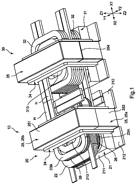
There is to provide a coil part capable of reducing the number of fastening means such as screws and so on required when attaching it to a substrate.
US 9,728,344 B2 · Assignee: Oregon State University · Inventors: Stucky; Galen et al.
Sheet 1 of 16 from the published document. All sheets in the USPTO PDF
An electrical double layer capacitor (EDLC) energy storage device is provided that includes at least two electrodes and a redox-enhanced electrolyte including two redox couples such that there is a different one of the redox couples for each of the electrodes. When charged, the charge is stored in Faradaic reactions with the at least two redox couples in the electrolyte and in a double-layer capacitance of a porous carbon material that comprises at least one of the electrodes, and a self-discharge of the energy storage device is mitigated by at least one of electrostatic attraction, adsorption, physisorption, and chemisorption of a redox couple onto the porous carbon material.
An electric double-layer capacitor, also known as a “supercapacitor,” “supercondenser,” “pseudocapacitor,” “electrochemical double layer capacitor” (EDLC),” or “ultracapacitor,” (hereinafter referred to as an “EDLC”) is an electrochemical capacitor that has an unusually high energy density when compared to common capacitors. EDLCs can have long cycle life and fast recharging times suitable to provide sufficient power demanded for heavy-duty electronics and electric vehicles. Multiple power applications favorably harness the high power of EDLCs instead of batteries with lower power output. In a battery, solid-state Faradaic processes often lead to poor cycling reversibility and limited power performance. EDLCs are based upon the electrochemical double layer phenomenon at the interface between a polarized electrode and a liquid electrolyte. An EDLC can include two electrochemical double la
1 of 16 drawing sheets so far from the published document, cropped to the drawing. Every sheet is in the USPTO PDF.
What the patent claimed, word for word. All of it is now free to use.
The present disclosure relates generally to energy storage devices. More particularly, the invention relates to energy storage devices including a redox-enhanced electrolyte.
An electric double-layer capacitor, also known as a “supercapacitor,” “supercondenser,” “pseudocapacitor,” “electrochemical double layer capacitor” (EDLC),” or “ultracapacitor,” (hereinafter referred to as an “EDLC”) is an electrochemical capacitor that has an unusually high energy density when compared to common capacitors. EDLCs can have long cycle life and fast recharging times suitable to provide sufficient power demanded for heavy-duty electronics and electric vehicles. Multiple power applications favorably harness the high power of EDLCs instead of batteries with lower power output.
In a battery, solid-state Faradaic processes often lead to poor cycling reversibility and limited power performance. EDLCs are based upon the electrochemical double layer phenomenon at the interface between a polarized electrode and a liquid electrolyte. An EDLC can include two electrochemical double layers linked in series by an electrolyte bridge. Operation of EDLCs can involve neither inter-electrode mass transfer nor solid-state ion diffusion, which can lead to long cycling life and high-power.
Significant progress has been made to EDLCs in terms of power densities and physical flexibility. Unfortunately, the low energy densities of current EDLCs, generally about <5 Watt hour per kilogram (Wh/kg), seriously limit the applications of the EDLC.
The present inventors recognize, among other things, that increasing the energy density of EDLCs while decreasing the cost of manufacture can be beneficial. The devices and methods of the present disclosure can decrease the cost to manufacture the EDLC while improving the energy density. For example, the EDLC of the present disclosure can include a redox-enhanced electrolyte having two redox couples and two electrodes (e.g., a positive electrode and a negative electrode). As discussed herein, when the redox couples become charged, the solubility of the redox couples change. For example, when a first redox couple becomes charged, the first redox couple can adsorb to the surface of a first electrode and when a second redox couple becomes charged, the second redox couple can adsorb to the surface of a second electrode, such that the self-discharge of the EDLC is minimized (e.g., prevented) and the EDLC can be fabricated without the use of an ion-selective membrane separator.
As discussed herein, current EDLCs can exhibit high power and long cycle life, but have low energy density compared to batteries, which can limit the application of EDLCs. High power density and long-term cycle stability, e.g., in load leveling and in electric vehicles, can be enabled by a double-layer charging mechanism which relies only on physical ion adsorption/desorption in the Helmholtz layer of the liquid electrolyte and does not require driving slower solid-state ion insertion/de-insertion reactions as in, e.g., lithium ion batteries, which also leads to electrode volume change and thus capacity fade with cycling.
Current EDLCs can use organic electrolytes to enable operation at voltages around, for example, about 3 Volts (V). The disadvantages of current EDLCs can include
low-to moderate volumetric and gravimetric energy density (e.g., about <10 Wh/kg or <8 Wh/L)
high costs of manufacture due to organic electrolytes (included to reach high voltages and thus relevant energy densities of about 10 Wh/kg) and high-purity activated carbon electrodes (included to reduce self-discharge at high voltages), and
safety concerns associated with using flammable organic electrolytes. These disadvantages limit the wide application of EDLCs.
To increase energy density, previous approaches have included adding redox-active oxides, e.g. RuO.sub.2 or MnO.sub.2, to electrodes to provide so-called “pseudo-capacitance” that is associated surface Faradaic redox chemistry. These devices exhibit compromised power performance and cycle lifetime, compared to EDLCs. Recently, incorporating solvated redox-active species into electrolytes has been reported to improve charge storage. One advantage of using soluble redox species is that the charge/discharge processes does not involve solid-state reactions or solid-state diffusion. However, an ion-selective membrane separator (such as a Nafion membrane) has been used to separate two different solutions (e.g., a KI solution and a VOSO.sub.4 solution) into two compartments of a cell, as a catholyte and an anolyte, respectively. However, the Nafion membrane is expensive and can limit the practical application of an EDLC incorporating the membrane. The use of the ion-selective membrane separator in previous approaches reflects the challenge of controlling the self-discharge reaction between a catholyte and an anolyte.
However, the present disclosure provides an ELDC where the traditional inert electrolyte is replaced with a redox-enhanced electrolyte including an integral active component for storing a charge. As discussed herein, the redox-enhanced electrolyte includes at least two redox couples such that there is a different one of the redox couples for each of the electrodes. That is, the redox-enhanced electrolyte can be oxidized at the positive electrode and reduced at the negative electrode during charging. As discussed herein, the EDLC of the present disclosure can provide an energy density of, for example, about 10 Wh/kg or greater, based on the mass of the electrode and the electrolyte, and about 50 Wh/kg or greater, based on the electrode mass only, without the use of an ion-selective membrane separator.
To better illustrate the energy storage devices and methods disclosed herein, a non-limiting list of examples is provided here:
Example 1 can include subject matter (such as a device) comprising an electrical double layer capacitor (EDLC) including at least two electrodes separated by a redox-enhanced electrolyte having an integral active component for storing a charge, where the redox-enhanced electrolyte includes at least two redox couples, such that there is a different one of the redox couples for each of the electrodes, wherein, when charged, the charge is stored in Faradaic reactions with the at least two redox couples in the electrolyte and in a double-layer capacitance of a porous carbon material that comprises at least one of the electrodes, and where a self-discharge of the energy storage device is mitigated by at least one of electrostatic attraction, adsorption, physisorption, and chemisorption of a redox couple onto the porous carbon material.
In Example 2, the subject matter of Example 1 can optionally include where the at least two redox couples are mixed into the electrolyte and the EDLC does not include an ion-selective separator.
In Example 3, the subject matter of one or both of Examples 1 and 2 can optionally include where the at least two redox couples do not comprise a metal.
In Example 4, the subject matter of one or any combination of Examples 1-3 optionally includes where at least one redox couple comprises a viologen.
In Example 5, the subject matter of one or any combination of Examples 1-4 can optionally include where at least one redox couple comprises Bromine.
In Example 6, the subject matter of one or any combination of Examples 1-5 can optionally include where the electrolyte is an aqueous, organic or ionic liquid.
In Example 7, the subject matter of one or any combination of Examples 1-6 can optionally include where a PH of the redox-enhanced electrolyte, concentrations and ratios of the at least two redox couples, and/or a porosity of the porous carbon material, are adjusted to control an internal self-discharge of the electrical double layer capacitor.
In Example 8, the subject matter of one or any combination of Examples 1-7 can optionally include where each of the at least two redox couples operates at a different potential.
In Example 9, the subject matter of one or any combination of Examples 1-8 can optionally include where the redox couples comprise any couple with a standard reduction potential within an operating voltage window of the electrical double layer capacitor.
Example 10 can include subject matter (such as a method), or can optionally be combined with the subject matter of one or any combination of Examples 1-9 to include such subject matter, comprising a method for fabricating an electrical double layer capacitor (EDLC) including at least two electrodes separated by a redox-enhanced electrolyte that comprises an integral active component for charge storage, where at least one electrode is fabricated from porous conductive carbon material, where the redox-enhanced electrolyte is fabricated to include at least two redox couples, such that there is a different one of the redox couples for each of the electrodes, where the charge is stored in Faradaic reactions with the at least two redox couples in the electrolyte, and where the redox couples comprise compounds having properties selected to inhibit internal self-discharge within the electrical double layer capacitor.
In Example 11, the subject matter of Example 10 can optionally include adjusting a PH of the redox-enhanced electrolyte, concentrations and ratios of the at least two redox couples, and/or a porosity of the porous carbon material, to control an internal self-discharge of the electrical double layer capacitor.
Example 12 the subject matter of one or any combination of Examples 10 or 11 can optionally include where the redox couples comprise compounds selected for their ability to mitigate self discharge of the device via electrostatic attraction adsorption, physisorption and/or chemisorption onto the porous conductive carbon material.
Example 13 the subject matter of one or any combination of Examples 10-12 can optionally include where (a) the device does not comprise an ion-selective separator; (b) the at least two redox couples do not comprise a metal; (c) at least one redox couple comprises a viologen; and/or (d) the electrolyte is an aqueous liquid.
Example 14 the subject matter of one or any combination of Examples 10-13 can optionally include where the device delivers an energy density of at least at least 10 Wh kg.sup.−1 based on the mass of electrodes and electrolyte.
Example 15 the subject matter of one or any combination of Examples 10-14 can optionally include where the device exhibits a self-discharge rate of less than 50 percent after three hours at open circuit.
Example 16 can include subject matter (such as a method), or can optionally be combined with the subject matter of one or any combination of Examples 1-15 to include such subject matter, comprising a method of inhibiting internal self-discharge of an energy storage device, wherein the device comprises: at least two electrodes, wherein at least one electrode comprises a porous carbon material; and an aqueous redox-enhanced electrolyte comprising a first redox active compound and a second redox active compound, wherein the electrolyte functions as an active component for charge storage, the method comprising: allowing the first redox active compound and/or the second redox active compound to adsorb to the porous carbon material via electrostatic attraction adsorption, physisorption and/or chemisorption, thereby mitigating self-discharge of the device so that internal self-discharge of the energy storage device in inhibited.
In Example 17, the subject matter of Examples 16 can optionally include where the device is an electrical double layer capacitor.
In Example 18, the subject matter of one or any combination of Example 16 or Example 17 can optionally include where the device does not include an ion-selective separator.
In Example 19, the subject matter of one or any combination of Examples 16-18 can optionally where a first redox active couple and a second redox active compound do not include a metal other than potassium or other not redox active counter-ions.
In Example 20, the subject matter of one or any combination of Examples 16-19 can optionally include where at least one redox active compound includes a viologen.
Example 21 can include, or can optionally be combined with any portion or combination or any portions of any one or more of Examples 1-20 to include, subject matter that can include means for performing any one or more of the functions of Examples 1-20.
These non-limiting examples can be combined in any permutation or combination.
These and other examples and features will be set forth in part in the following Detail Description. This Summary is intended to provide a brief overview of subject matter of the present patent application. It is not intended to provide an exclusive or exhaustive explanation of the invention. The detailed description is included to provide further information about the present patent application such as a discussion of the dependent claims and the interrelation of the dependent and independent claims in addition to the statements made in this section.
In the drawings, which are not necessarily drawn to scale, like numerals may describe similar components in different views. Like numerals having different letter suffixes may represent different instances of similar components. The drawings illustrate generally, by way of example, but not by way of limitation, the various examples discussed in the present document.
FIG. 1A illustrates an energy storage device during charging, in accordance with at least one example.
FIG. 1B illustrates an energy storage device during discharging, in accordance with at least one example.
FIG. 2 illustrates reduction potentials for various potential redox couples.
FIG. 3A illustrates the galvanostatic charge/discharge profile of a cell including potassium iodide (KI).
FIG. 3B illustrates the galvanostatic charge/discharge profile of a cell including potassium bromide (KBr).
FIG. 3C illustrates the galvanostatic charge/discharge profile of a cell including cobalt trisbipyridine dicholoride (Co(bpy).sub.3.sup.2+/3+).
FIG. 3D illustrates the galvanostatic charge/discharge profile of a cell including potassium ferrocyanide (K.sub.4Fe(CN).sub.6).
FIG. 4A illustrates the galvanostatic charge/discharge profile of a cell including methyl viologen dichiloride (MVCl.sub.2).
FIG. 4B illustrates the galvanostatic charge/discharge profile of a cell including ruthenium hexamine dicholoride (Ru(NH.sub.3).sub.6.sup.2+).
FIG. 5A illustrates the energy retention for the cells including KI, KBr, Co(bpy).sub.3.sup.2+/3+, and (K.sub.4Fe(CN).sub.6).
FIG. 5B illustrates the energy retention for the cells including potassium sulfate (K.sub.2SO.sub.4), MVCl.sub.2, and Ru(NH.sub.3).sub.6.sup.2+.
FIG. 6 illustrates the cyclic voltammogram of a cell including KI and MVCl.sub.2.
FIG. 7 illustrates the cyclic voltammogram of a cell including KBr/MVCl.sub.2 and HVBr.sub.2.
FIG. 8 illustrates the voltammograms for the complete cell including KBr/MVCl.sub.2.
FIG. 9 illustrates the voltammograms for the complete cell including HVBr.sub.2.
FIG. 10 illustrates the galvano static charge/discharge profile for a cell including KBr/MVCl.sub.2.
FIG. 11 illustrates the galvanostatic charge/discharge profile for a cell including HVBr.sub.2.
FIG. 12 illustrates the energy retention for a cell including KBr/MVCl.sub.2 and HVBr.sub.2.
FIG. 13 illustrates the energy retention for the control cells tested with an inert electrolyte.
FIG. 14 illustrates a Ragone plot of redox-EDLC performance from volume-limiting cells. The inset illustrates the cycling stability for a cell including KBr/MVCl.sub.2 and KBr/HVBr.sub.2.
FIG. 15 illustrates cell potential for model calculations compared to experimental data for galvano static charge/discharge profiles.
FIG. 16 illustrates the theoretical specific energy using the electrochemical model for the cell including KBr/MVCl.sub.2.
FIG. 17 illustrates the N.sub.2 adsorption/desorption graph and BET pore size distribution curve for the porous carbon material.
FIG. 18A illustrates the galvano static charge/discharge profile for an aqueous-based commercial supercapacitor.
FIG. 18B illustrates the self-discharge data for the aqueous-based commercial supercapacitor.
FIG. 19A illustrates the galvanostatic charge/discharge profile for an organic based commercial supercapacitor.
FIG. 19B illustrates the self-discharge data for the organic based commercial supercapacitor.
FIG. 20A illustrates the galvanostatic charge/discharge profile for a lab-made EDLC composed of CO.sub.2 activated carbon electrodes and 0.5 M K.sub.2SO.sub.4 (99.99% pure) solution.
FIG. 20B illustrates the self-discharge data for the lab-made EDLC composed of CO.sub.2 activated carbon electrodes and 0.5 M K.sub.2SO.sub.4 (99.99% pure) solution.
While the disclosure is amenable to various modifications and alternative forms, specific embodiments have been shown by way of example in the drawings and are described in detail below. The intention, however, is not to limit the disclosure to the particular embodiments described. On the contrary, the disclosure is intended to cover all modifications, equivalents, and alternatives falling within the scope of the disclosure as defined by the appended claims.
In the following detailed description, reference is made to the accompanying drawings which form a part hereof, and specific embodiments in which the disclosure may be practiced are shown by way of illustration. It is to be understood that other embodiments may be used and structural changes may be made without departing from the scope of the present disclosure.
The current disclosure provides an energy storage device including an EDLC having at least two electrodes separated by a redox-enhanced electrolyte that comprises an integral active component for charge storage. For example, the redox-enhanced electrolyte can include two redox couples, such that there is a different one of the redox couples for each of the electrodes (e.g., positive and negative electrodes). By replacing an inert electrolyte with the redox-enhanced electrolyte, additional faradaic charge storage mechanisms can be added to the underlying capacitive ones, as discussed herein. The energy storage device of the present disclosure can increase capacity by utilizing previously “unused” electrolyte mass for energy storage, while maintaining the power and charge-discharge cyclability for appropriate redox-active couples. The energy storage device of the present application also includes aqueous electrolytes and less-expensive carbons, both of which can lower the costs relative to non-aqueous systems.
The EDLC of the present disclosure can provide a redox-enhanced electrolyte including two redox-couples that can significantly improve the energy density of the EDLC. In an example, when charged, a first redox-couple of the electrolyte can be adsorbed on a first electrode and a second redox-couple of the electrolyte can be adsorbed on a second electrode, therefore preventing rapid self-discharge. The EDLC of the present disclosure can retain the key advantages of EDLCs while incorporating Faradaic energy-storage without using ion-selective membrane separators. In an example, the EDLC of the present disclosure can exhibit energy densities from 10 to 15 Wh/kg (based on electrode mass) and stable capacities for greater than 20,000 cycles. Theoretically, this could range from 5-100 Wh/kg.
The redox-enhanced electrolyte can be a mixed solution including the two redox couples, which integrate both Faradaic and capacitive energy storage in the same device. The electrodes can become polarized when charged and retard diffusion of the oppositely-charged redox ions to mitigate self-discharge, such that the EDLC does not need an ion-selective membrane as a separator. During charging, the redox-enhanced electrolyte evolves into both a catholyte including a first redox couple and an anolyte including a second redox couple (as shown in FIGS. 1A and 1B ). The EDLC involves no solid-state phenomena during operation, no ion-selective membrane separator, and a single electrolyte. The EDLC of the present disclosure is fundamentally different form previous devices, including pseudo-capacitors, batteries and Nafion-containing capacitors.
Prior to applying a charge to the electrodes, the redox-enhanced electrolyte includes a first redox couple and a second redox couple mixed together. However, once a charge is applied to the electrodes, a portion of the charge is transferred to the first redox couple and the second redox couple. As discussed herein, when the charge is transferred to the first and second redox couples, the solubility of the redox couples change, such that they adsorb on their respective charged electrode surface. In other words, when charged, an anolyte including a first redox couple is formed and absorbed on the surface of a negative electrode and a catholyte including a second redox couple is formed and absorbed on the surface of a positive electrode. As used herein, “absorbed” can be defined as the adhesion of ions or molecules to a surface, which creates a film of the adsorbate on the surface of the adsorbent. Above, the word catholyte is synonymous with “oxidized form of the redox couple undergoing redox reactions at the positive electrode” and anolyte is synonymous with “reduced form of the redox couple undergoing redox reactions at the negative electrode”. Catholyte and anolyte can also refer to each redox couple, and do not necessarily refer to only one oxidation state of the couple.
FIG. 1A illustrates an energy storage device 10 during charging and FIG. 1B illustrates the energy storage device 10 during discharging, in accordance with at least one example. The energy storage device 10 can include at least two electrodes, for example, a negative electrode 12 and a positive electrode 14 (referred to herein collectively as “electrodes 12 , 14 ”).
In an example, the electrodes 12 , 14 can include a porous material. For example, the electrodes 12 , 14 can include one or more of, but are not limited to, activated carbons, carbide derived carbons, carbon nanotubes, mesoporous carbons, graphenes, reduced graphene oxides, metal oxides, and conducting polymers. In one example, the electrodes 12 , 14 can include activated carbon. In an example, the electrodes 12 , 14 can have a porosity within a range of about 300 square meter per gram (m.sup.2/g) to about 3000 m.sup.2/g. For example, the electrodes 12 , 14 can have a porosity within a range of about 1500 m.sup.2/g to about 2500 m.sup.2/g, such as 1600 m.sup.2/g, 1700 m.sup.2/g, 1800 m.sup.2/g, 1900 m.sup.2/g, 2000 m.sup.2/g, 2100 m.sup.2/g, 2200 m.sup.2/g, 2300 m.sup.2/g, and 2400 m.sup.2/g. Because the redox-enhanced electrolyte contributes substantially to the charge storage capacity of the device and the surface of the carbon participates in the absorption phenomena that prevents self discharge, carbons for redox-EDLCs can include both reasonably large surface areas but also large pore volumes and thus lower overall densities than those typically used for traditional non-redox EDLC devices.
The electrodes 12 , 14 can include other components such as binders, conductive additives, and porogens. In an example, the binders can be selected from, but not limited to, polytetrafluoroethylene (PTFE), polyvinylidene difluoride (PVDF), and poly-ionic liquids. In an example, the conductive additives can be selected from, but not limited to, acetylene black, graphene, reduced graphene oxide, and carbon nanotubes.
As shown in FIGS. 1A and 1B , the EDLC 10 can include a redox-enhanced electrolyte 16 including a first redox couple 18 and a second redox couple 20 . As discussed herein, the redox-enhanced electrolyte 16 can be a single electrolyte that upon charging can evolve into both an anolyte and a catholyte such that a first redox couple 18 is positioned along a surface of a first electrode 12 and the second redox couple 20 is positioned along a surface of the second electrode 14 . The first redox couple 18 is labeled O.sub.n/R.sub.n (e.g., anolyte) and can be used at the negative electrode 12 . The first redox couple 18 can be reduced upon charging, and oxidized upon discharge. The second redox couple 20 is labeled O.sub.p/R.sub.p (e.g., catholyte) and can be used at the positive electrode 16 . The second redox couple 20 can be oxidized upon charging and reduced upon discharge.
As discussed herein, the redox-enhanced electrolyte 16 can be an aqueous, organic, or ionic liquid and include the first redox couple 18 and the second redox couple 20 . The first redox couple 18 for the negative electrode 12 can have standard potentials at or slightly more-cathodic than the hydrogen evolution potential, as well as high solubility and solution compatibility with the catholyte. To minimize or prevent rapid self-discharge, the first redox couple 18 can have a positive charge and physically adsorb on the negative electrode 12 (e.g., activated carbon) following charging.
The second redox couple 20 for the positive electrode 14 can have a reduction potential near, or slightly more positive/anodic than, the oxygen evolution potential to maximize energy density, as well as high solubility and solution compatibility with the anolyte. To minimize or prevent rapid self-discharge, the second redox couple 20 can have a negative charge and physically adsorb on the positive electrode 14 (e.g., activated carbon) following charging.
In an example, the first redox couple 18 can include a viologen and the second redox couple 20 can include a halide (e.g., bromine). In an example, the first and second redox couples 18 , 20 do not comprise a metal. The metal-free redox couples are advantageous because they can be less expensive, easier to recycle, do not form dendrites, and are less environmentally harmful. The first redox couple 18 and the second redox couple 20 can be chosen such that the first and second redox couples 18 , 20 operate at a different potential.
Viologens are derivatives of 4,4′-bipyridyl. An example of the dicationic 4,4′-bipyridinium portion of a viologen is shown below.
Examples of this viologen are methyl viologen (R=methyl), ethyl viologen (R=ethyl), and benzyl viologen (R=benzyl). These viologens have been isolated as salts of the chloride (Cl.sup.−), acetate (CH.sub.3CO.sub.2.sup.−) tetraflurorborate (BF.sub.4.sup.−), perchlorate (ClO.sub.4.sup.−), triflurormethanesulfonate (CF.sub.3SO.sub.3.sup.−), tetraphenylborate (BPh.sub.4.sup.−), and hexaflurophosphate (PF.sub.6.sup.−), to name a few. FIG. 2 illustrates the standard redox potential for methyl, ethyl, heptyl, and benzyl viologen. Each of redox couples for methyl, ethyl, heptyl, and benzyl are stable in neutral conditions. The SCE is the standard calomel electrode.
In an example, the first redox couple 18 can include one of methyl viologen and heptyl viologen. As shown in FIG. 2 , the standard potentials for methyl and heptyl viologens are at or slightly more-cathodic than the hydrogen evolution potential. In an example, a concentration of the first redox couple 18 can be within a range from about 0.1 molar (M) to about 5 M, such as 0.1 M.
In one example, the second redox couple 20 can include bromine (Br), which is generally inexpensive and highly soluble (greater than 1 M). Further, as shown in FIG. 2 , the aqueous reduction potential of bromine is located above the thermodynamic oxygen evolution potential. In an example, a concentration of the second redox couple 20 can be within a range of about 0.1 M to about 5M, such as about 0.4 M to about 1 M.
The EDLC of the present disclosure can retain the key advantages of EDLCs while incorporating Faradaic energy-storage without using ion-selective membrane separators. In an example, an EDLC including MV and Br can exhibit energy densities of about 14 Wh/kg (based on electrode mass) and an EDLC including HV and Br can exhibit energy densities of about 10 Wh/kg (based on electrode mass) and have stable capacities for greater than 20,000 cycles. Further, the EDLCs of the present disclosure can provide a self-discharge rate of less than 50 percent (%) after 3 hours at open-circuit (i.e. the energy density for a discharge 3 hours after charging is more than 50% of the discharge energy density immediately after charging) for an EDLC including MV and Br as the redox-couples. An EDLC including HV and Br and the redox-couples, the self-discharge rate can be less than 10%-20% (80%-90% retained) over 6 hours.
In an example, the EDLCs of the present disclosure can deliver power densities >1 kW/kg, based on mass of electrodes and electrolyte, which sets them apart from many energy storage technologies. Conventional EDLCs can have a voltage that varies linearly with the state of charge, so the charge-discharge curves are triangular, which can be undesirable for many applications. The ELDCs of the present disclosure exhibit EDLC behavior initially, then transition to battery like behavior at higher voltages, delivering a desirable steady voltage. Together, these properties can provide the high power density of supercapacitors along with the constant potential and high energy density of batteries.
Analysis of Potential Redox-couples for the Positive Electrode
In order to determine potential redox couples for the positive electrode (e.g., electrode 14 ), various candidates were tested in a three-electrode Swagelok cell. FIGS. 3A and 3B illustrate the galvanostatic cycling profiles of KI and KBr, respectively. The galvanostatic cycling profiles of the candidate redox-couples were tested in a three-electrode Swagelok cell. The charge/discharge profiles (shown as dashed lines) are shown for the positive electrode (middle line) and the negative electrode (bottom line). The cells were charged/discharged at a rate of 1 A g.sup.−1.sub.(+) electrode (normalized to the mass of the positive electrode only, because the negative electrode mass was varied to accommodate couples with different redox potentials) to a total cell voltage of 1 V. The middle and bottom lines show the potential of the positive and negative electrodes, respectively, referenced to the centrally placed SCE. For 1 M KI, the positive electrode potential narrowly varied between 0.02 V and 0.19 V vs. SCE, suggesting oxidation of I.sup.− to I.sub.3.sup.−. The negative electrode potential varied linearly with charge between 0.02 V and −0.91 V vs. SCE indicating a double-layer charging mechanism with inert K.sup.+.
For 1 M KBr, the positive electrode shows two distinct charging regimes.
For the first 60 seconds (s), the electrode potential depends linearly on the charge added, indicating capacitive charging with Br.sup.− in the double layer. For the next 60 s the potential increases to about 0.7 V vs. SCE, suggesting oxidation of Br.sup.− to B.sub.r3.sup.− (or Br.sup.2). The negative electrode showed purely capacitive charging. The high redox potential of Br.sup.−/Br.sub.3.sup.− is advantageous for increasing energy density.
EDLC self-discharge is commonly studied by monitoring the potential decay at open circuit. However, because the charge is not a linear function of potential for redox-EDLCs, the remaining energy in the cell was measured by complete discharge at each time point. The results are shown in FIG. 5A , which illustrates the energy retention for KI, KBr, Co(bpy).sub.3.sup.2+/3+, and (K.sub.4Fe(CN).sub.6).
The self-discharge profiles of KI and KBr show energy retention of 76% and 43% after 6 hours, respectively. Remarkably, the self-discharge rate of the KI cell is closer than that of the control K.sub.2SO.sub.4 cell when also charged to 1 V (energy retention=67% after 6 hours; shown in FIG. 5B ). Given the lack of an ion-selective membrane, the slow self-discharge of the cells is unexpected. After charging the KI cell, a large concentration gradient of I.sup.3− and I.sup.− between the positive and negative electrode is present that would normally be expected to drive diffusive transport across the cell resulting in fast self-discharge.
Not to be bound by theory, but one hypothesis to explain the remarkably slow self-discharge is that the negatively charged oxidation products I.sub.3.sup.− or Br.sub.3.sup.− are electrostatically held in the double layer of the positively charged activated carbon electrode. To test this, cells were fabricated with potassium ferrocyanide K.sub.4Fe(CN).sub.6 and cobalt trisbipyridine dichloride Co(bpy).sub.3Cl.sub.2 redox-active electrolytes. Both couples have reduction potentials similar to and undergo fast one-electron oxidations suitable for testing at the positive electrode. Co(bpy).sub.3.sup.2+/3+ has a positive charge, and thus would be expected to be expelled from the double layer at the positive electrode (where it is oxidized) and subsequently reduced after diffusing to the negative electrode, thus increasing the self-discharge rate. Fe(CN).sub.6.sup.4−/3− has a negative charge, like I.sub.3.sup.−/I.sup.−, and thus might also show retarded self-discharge if electrostatic effects play the dominate role.
FIGS. 3C and 3D illustrate the galvanostatic charge/discharge profiles for cells including Co(bpy).sub.3Cl.sub.2 and K.sub.4Fe(CN).sub.6, respectively. The galvanostatic charging behavior at the positive electrode (middle line) for K.sub.4Fe(CN).sub.6 and Co(bpy).sub.3Cl.sub.2 is similar to the KI cell with the electrode potential pinned near the standard potential of the couple ( FIG. 3A ). The negative electrodes (bottom line) show capacitive (linear potential-time) response on charging, while upon discharging an additional potential loss is measured that is associated with the low ionic conductivity of the 0.1 M redox-active electrolytes.
The Co(bpy).sub.3Cl.sub.2 and K.sub.4Fe(CN).sub.6 cells have 89.5% and 90.8% coulombic efficiency, respectively, which is substantially lower than the 99.9% and 98.8% measured for the KI and KBr cells, respectively (see Table 1).
As shown in FIG. 5A , the Co(bpy).sub.3Cl.sub.2 cell loses half of its energy in 1 min, while the K.sub.4Fe(CN).sub.6 cell takes 5 min to lose half of its energy. This data is consistent with electrostatics contributing to the self-discharge in the case of Co(bpy).sub.3.sup.2+/3+ and retarding it in the case of Fe(CN).sub.6.sup.4−/3− and for the halides. However, despite the large negative charge of Fe(CN).sub.6.sup.4−/3− its self-discharge rate is still roughly 100 times faster than that of I.sub.3.sup.−/I.sup.−. The retarded self-discharge for the halides cannot be explained purely by electrostatics.
A likely mechanism to explain the slow self-discharge of the halides is physical adsorption of the oxidized species within the activated carbon surface leading to slow cross diffusion. The total charge passed associated with I.sup.− oxidation during galvanostatic charging is 0.620 C. Assuming a footprint of ˜2.5×10.sup.−19 m.sup.−2 I.sub.3.sup.−, complete adsorption would only cover 3.6% of the activated carbon surface in the positive electrode. This small level of required coverage is consistent with physical adsorption being the primary mechanism preventing self-discharge and electrostatic effects being secondary. For both the KBr and KI cells the observed potential plateau at the positive electrode ( FIGS. 3A and 3B ) is ˜0.1 V less positive than the standard potential of the respective couples. This is consistent with specific adsorption stabilizing the oxidized halide, thus shifting the formal potential of the couple positive of the standard potential within the activated carbon.
Analysis of Potential Redox-couples for the Negative Electrode
As discussed herein, redox couples for the negative electrode O.sub.n/R.sub.n can have standard potentials at or slightly more-cathodic than the hydrogen evolution potential, as well as high solubility and solution compatibility with the catholyte. To prevent rapid self-discharge, O.sub.n/R.sub.n can have a positive charge and physically adsorb on the activated carbon following charging.
Viologen dications (4,4′-dipyridinium compounds) are positively charged, highly soluble redox couples, with formal potentials negative of the hydrogen potential and fast, reversible, kinetics. Methyl viologen dichloride (MVCl.sub.2) was studied due to its negative reduction potential (E.sup.o=−0.69 V vs. SCE) and commercial availability, and low cost (e.g., <$5 kg.sup.−1 in bulk, used as a common agricultural chemical). Being a nearly co-planar π-π conjugated ring system, MVCl.sub.2 can adsorb on activated carbon surfaces. Stronger adsorption is likely after reduction of MV.sup.2+ to MV.sup.+ due to decreased charge density and increased co-planarity of the two adjacent rings.
In order to study the viologen electrochemistry in the absence of a redox-active electrolyte at the positive electrode, a 4:1 mass ratio for the positive:negative electrode was used (the counter ion is inert over the accessible potential range). FIG. 4A illustrates the galvanostatic charge/discharge profile for a cell including MVCL.sub.2. During galvanostatic charging, the positive electrode (middle line) potential varied nearly linearly with time while the negative electrode (bottom line) potential curves substantially with time near about −0.5 V vs. SCE. The self-discharge rate of the MVCl.sub.2 electrolyte was measured (as shown in FIG. 5B ) and was found comparable to that of the EDLC with 0.5 M K.sub.2SO.sub.4, suggesting that the redox couple does not contribute substantially to self-discharge via redox shuttling.
To understand the self-discharge processes in the MV.sup.2+ electrolytes, a ruthenium hexamine dichloride electrolyte was studied (shown in FIG. 4B ). Ru(NH.sub.3).sub.6.sup.3+/Ru(NH.sub.3).sub.6.sup.2+ is cationic, like MV.sup.2+/MV.sup.+, but is unlikely to specifically absorb on the activated carbon surface because of its near-spherical molecular shape. The Ru(NH.sub.3).sub.6Cl.sub.3 cell shows double-layer charging with Cl.sup.− on the positive electrode and some faradaic charging on the negative electrode with a slight plateau near −0.2 V consistent with the reduction of ruthenium hexamine (E.sup.o˜−0.14 V vs. SCE). The self-discharge rate, however, is significantly faster for Ru(NH.sub.3).sub.6Cl.sub.3 than for MVCl.sub.2, providing further evidence that electrostatic effects are not sufficient to prevent self-discharge and that MV.sup.+ adsorbs on the carbon electrode as do the halide ions.
Redox-Enhanced Electrolyte Systems
The EDLC of the present disclosure includes the redox-enhanced electrolyte for the positive and negative electrodes. All species in both redox states (O.sub.n, R.sub.n, O.sub.p, R.sub.p) can stable in the same electrolyte to reduce manufacturing complexity. Based on the results from studying the individual couples, halogen/viologen electrolytes were studied.
MVCl.sub.2/KI is stable in the uncharged state but forms MV.sup.+-I.sup.− precipitate upon charging leading to irreversible capacity loss (as shown in FIG. 6 ). For example, FIG. 6 illustrates the cyclic voltammogram of the mixed 0.3 M KI/0.3 MVCl.sub.2 solution collected at 5 mV s.sup.−1. A three-electrode half-cell configuration was used, with GC disc working electrode, coiled Pt counter electrode and SCE reference electrode. In cathodic scans, the reduction peak of MV.sup.2+ was observed near −0.7 V in the CV. Simultaneously, a black spike-shaped solid grew on the GC surface identified as irreversible MV.sup.19 +-I.sup.31 formation. Moreover, the redox reaction of I.sup.−/I.sub.3.sup.− was not observed.
The description continues in the full USPTO document.
About 5,935 words. The USPTO PDF has it with every drawing.
Fees are due 3.5, 7.5 and 11.5 years after grant. This patent expired on August 8, 2025, so the fee marked "not paid" was the one that went unpaid.
ENERGY STORAGE DEVICE INCLUDING A REDOX-ENHANCED ELECTROLYTE
Filed Apr 2015 · published Oct 2016Energy storage device including a redox-enhanced electrolyte
Filed Apr 2015 · granted Aug 2017Earlier publications, parents and continuations. None of them can still be enforced, or this patent would not be listed.
Prior art cited by the examiner or applicant. Useful when you check your own idea for novelty.
Everything on this page comes from the documents linked above.