Cross-reference to related applications
The present application is the U.S. national stage application pursuant to 35 U.S.C. §371 of international Application No. PCT/EP2013/062455, filed on Jun. 17, 2013, which application claims priority from German Patent Application No. DE 10 2012 211 486.6, filed on Jul. 3, 2012, which applications are incorporated herein by reference in their entireties.
Technical field
The invention relates generally to a lever system for actuating at least one clutch, and, more specifically, to a lever system for actuating at least one clutch comprising at least one pivotable lever that has a certain bending rigidity. The invention further relates to an actuating device for actuating at least one clutch by means of a lever system of this type. The invention further relates to a clutch device comprising at least one clutch that has a regressive characteristic map and is actuated by a lever system of this type.
Background
The published German Patent Application No. DE 10 2004 009 832 A1 (Friedman et al.) describes a lever system for actuating clutches comprising a lever with a first side and a second side and with at least one point of contact, which may simultaneously represent a fulcrum.
The published German Patent Application No. DE 10 2006 043 330 A1 (Reefer et al.) describes a lever system for actuating a clutch comprising a lever that is supported for rotation about a joint on one side and in operative connection with a pressure means on the other side. In a point of contact located on a cam track, the lever is supported on a carriage that is displaceable in a radial direction by means of a motor-driven spindle.
Summary
The invention is a lever system for actuating at least one clutch comprising at least one pivotable lever having a certain flexural rigidity wherein the lever has at least one flexurally elastic region that is designed and/or arranged in such a way that the flexural rigidity of the lever varies as a function of an actuating path of the clutch.
An object of the invention is to improve the actuation of clutches that have a regressive characteristic map.
In accordance with the invention, in a lever system for actuating at least one clutch comprising at least one pivotable lever that has a certain flexural rigidity, this object is attained by the fact that the lever has at least one elastic region that is designed and/or arranged in such a way that that the flexural rigidity of the lever varies as a function of the actuating path of the clutch. In this way, characteristic map curves of a characteristic map plotting the actuation force above the actuating path of the clutch may advantageously diverge. The lever system of the invention is preferably used as a clutch actuator in automated transmissions, in particular in twin clutch transmissions.
In accordance with an example embodiment of the lever system, the lever has a negative rigidity gradient across the actuating path of the clutch. The rigidity of the lever decreases as the actuating path of the clutch increases.
In accordance with another example embodiment of the lever system, an actuating contact area is arranged between a pivot for pivotably arranging the lever and a region of contact for a roller. In the actuating contact region, the lever gets into contact with an actuating element of the clutch. The actuating element may be an axial bearing, for example. In the point of contact, the lever is supported on a traverse carriage that is displaceable in a radial direction by means of a motor-driven spindle.
In accordance with a further example embodiment of the lever system, a cam track for the roller is formed in the region of contact on the lever in such a way that the actuating path of the clutch increases as the distance between the roller and a clutch axis increases. What is referred to as a clutch axis is an axis of rotation of the clutch, for example. The internal rigidity of the lever causes the effective actuation rigidity of the lever to decrease as the distance between the region of contact of the roller and the clutch axis increases.
In accordance with an example embodiment of the lever system, the flexurally elastic region is arranged between the actuating contact region and the pivot for pivotably arranging the lever. The flexural elasticity in the flexurally elastic region may be implemented by the use of less or different material.
In accordance with an example embodiment of the lever system, the flexurally elastic region extends from the pivot for pivotably arranging the lever beyond the actuating contact region. Thus, a sufficient degree of deformation may be attained in a simple way without exceeding the tension limits of the material.
In accordance with an example embodiment of the lever system, the flexurally elastic region is implemented by a counter-spring rigidity associated with the pivot for pivotably arranging the lever. The pivot may be spring-mounted with the aid of a spring device. Due to the spring device, which has a defined rigidity, the pivot may be displaced to a limited extent in a direction parallel to a line of action of the actuation force of the clutch.
In accordance with an example embodiment of the lever system, the lever for actuating two partial clutches of a twin clutch is combined with a lever actuator. The lever actuator is preferably arranged to be perpendicular to the lever of the invention. The lever actuator may be embodied as a lever engagement element as described in international patent application publication no. WO 2008/154896 A1 (Franz et al.).
The invention further relates to an actuating device for actuating at least one clutch, comprising a lever system as described above. Depending on the construction of the clutch, the actuating device may be referred to as an engagement device.
The invention furthermore relates to a clutch device comprising at least one clutch that has a regressive characteristic map and is actuated by the lever system described above. Depending on the construction of the clutch, an actuation of the clutch may also be referred to as an engagement of the clutch. With the aid of the lever system of the invention, a characteristic map that is comparatively rigid for small engagement paths of the clutch and becomes softer for longer engagement paths may be implemented in a simple way.
These and other objects, advantages and features of the present invention will be better appreciated by those having ordinary skill in the art in view of the following detailed description of the invention in view of the drawings.
Brief description of the drawings
The invention will now be described in greater detail by reference to the accompanying figures, in which the figures represent the following:
FIG. 1 is a simplified representation of a lever system of the invention having an elastic region;
FIG. 2 illustrates a lever system similar to the one shown in FIG. 1 comprising a counter-spring rigidity associated with a pivot of the lever system;
FIG. 3 illustrates a lever system similar to the one shown in FIG. 1 comprising a larger flexurally elastic region;
FIG. 4 illustrates an embodiment of the lever system shown in a simplified way in FIG. 3 ;
FIG. 5 illustrates the lever system of FIG. 4 with an additional lever actuator;
FIG. 6 illustrates a Cartesian coordinate system with a characteristic map of the lever system of FIG. 4 ; and,
FIG. 7 illustrates a Cartesian coordinate system with a characteristic map that incorporates a counter-spring.
Detailed description of the invention
At the outset, it should be appreciated that like drawing numbers on different drawing views identify identical, or functionally similar, structural elements of the invention. While the present invention is described with respect to what is presently considered to be the preferred aspects, it is to be understood that the invention as claimed is not limited to the disclosed aspects.
Furthermore, it is understood that this invention is not limited to the particular methodology, materials and modifications described and, as such, may, of course, vary. It is also understood that the terminology used herein is for the purpose of describing particular aspects only, and is not intended to limit the scope of the present invention, which is limited only by the appended claims.
Unless defined otherwise, all technical and scientific terms used herein have the same meaning as commonly understood to one of ordinary skill in the art to which this invention belongs. Although any methods, devices or materials similar or equivalent to those described herein can be used in the practice or testing of the invention, the preferred methods, devices, and materials are now described.
FIGS. 1 to 3 are simplified representations of various exemplary embodiments of lever system 1 , 21 , and 31 of the invention. In the drawings, identical or similar elements are indicated by identical reference symbols. The first few paragraphs that follow will describe the aspects lever systems 1 , 21 , and 31 have in common. Then the differences between the individual exemplary embodiments will be explained.
Lever system 1 , 21 , and 31 comprises lever 4 that is arranged in a hinge-like manner to pivot on a (non-illustrated) support structure as indicated by pivot 5 . Due to its pivotal or hinge-like arrangement, lever 4 may be referred to as a hinge lever.
Pivot 5 is formed on one end of lever 4 . The opposite end of lever 4 rests on carriage 8 . As indicated by double-headed arrow 10 , carriage 8 is movable back and forth in a horizontal direction. For this purpose, rollers are provided on the bottom of carriage 8 to roll on a corresponding track in a horizontal direction.
A corresponding cam track of lever 4 rests on an upper roller of carriage 8 . The shape of the cam track formed on lever 4 is selected such that as indicated by double-headed arrow 12 , an actuating contact region of the lever moves upward when carriage 8 moves away from pivot 5 .
Double-headed arrow 12 is located on line of action 13 of the actuation force of the clutch. When carriage 8 moves towards pivot 5 , lever 4 with its actuating contact region moves downward.
Carriage 8 with the rollers and the cam track on lever 4 form a cam mechanism integrated in lever system 1 , 21 , and 31 . The opposing arrangement of pivot 5 and carriage 8 or rather the cam mechanism causes an actuation three of the clutch, also referred to as an engagement force, to be distributed between carriage 8 and pivot 5 . As a result, the overall force for actuating the clutch may be lower than in the case of a lever actuator as described in the international patent application publication no. WO 2008/154896 A1, for instance.
In lever system 1 shown in FIG. 1 , double-headed arrow 16 indicates distance R.sub.R between carriage 8 and line of action 13 of the actuation force. Double-headed arrow 17 indicates distance L.sub.1 between line of action 13 and flexurally elastic region 14 . Further double-headed arrow 18 indicates distance L.sub.0 between line of action 13 and pivot 5 .
Flexurally elastic region 14 has flexural rigidity c.sub.T indicated in newton meters per rad. Based on flexural rigidity c.sub.T, the effective actuation rigidity or engagement rigidity of lever 4 is calculated as follows:
c eff = c T ( 1 R R + L 1 + 1 L 0 - L 1 ) ( 1 R R + L 1 R R + 1 L 0 - L 1 ) for L 1 ≥ 0 c eff = c T ( 1 R R + L 1 + 1 L 0 - L 1 ) ( 1 L 0 + L 0 - L 1 L 0 ( R R + L 1 ) ) for L 1 ≤ 0
The effective rigidity progressively diverges the closer flexurally elastic region 14 is to carriage 8 . If L.sub.1 equals zero, i.e. if flexurally elastic region 14 is arranged in the region of the intersection between line of action 13 and lever 4 , i.e. directly beneath the engagement system, the equation reads:
c eff _ 1 = c T ( 1 R R + 1 L C ) 2
If the position of carriage 8 (R.sub.R) varies between 40 and 80 millimeters and L.sub.1 equals zero, the effective rigidity changes by a factor nine to four.
The internal rigidity or elasticity of lever 4 causes the effective engagement rigidity of lever 4 to decrease as the distance of the point of contact on the upper roller of carriage 8 increases. Thus, an increasing axial distance between the upper roller of carriage 8 and pivot 5 results in a decreasing rigidity of lever system 1 as the engagement or actuating path increases.
In lever system 21 shown in FIG. 2 , flexurally elastic region 24 of lever 4 is represented by counter-spring 25 , which has a defined rigidity, also referred to as counter-spring rigidity. Counter spring 25 is arranged directly beneath pivot 5 .
Double-headed arrow 26 indicates distance R.sub.R between carriage 8 and line of action 13 . Double-headed arrow 27 indicates sum R.sub.R plus L.sub.0. For lever system 21 shown in FIG. 2 , due to the translation of the counter-spring rigidity on lever 4 supported on the upper roller as a fixed point, the effective engagement rigidity of lever 4 is calculated as follows:
i = R R R R + L 0
The effective rigidity in the actuating region, i.e. in the intersection between line of action 13 and lever 4 , is calculated as follows:
c eff _ 2 = c G i 2
If the counter-arm of lever 4 has length L.sub.0 of 80 millimeters and the roller path of carriage 8 described above is between 40 and 80 millimeters, for example, the effective rigidity likewise varies by a factor nine to four.
In lever system 31 shown in FIG. 3 , lever 4 has flexurally elastic region 34 that is significantly larger than flexurally elastic region 14 of lever system 1 shown in FIG. 1 . Flexurally elastic region 34 on lever 4 extends from pivot 5 beyond the actuating contact region of lever 4 . This is a simple way of allowing the lever to be sufficiently deformed without exceeding tension limits of the material lever 4 is made of.
FIG. 4 is a perspective view of an embodiment of lever system 41 including lever 44 . On one end, lever 44 has a curved section formed like a depression to indicate pivot 45 . Carriage 48 is associated with the opposite end of lever 48 . Lever 48 is movable on base plate 50 . Roller 51 is supported for rotation on carriage 48 . Lever 44 has a cam track that rests on roller 51 . Two further rollers 52 , 53 are provided for the carriage to be movable on base plate 50 .
Approximately at the center on its upper side, lever 44 has actuating contact region 55 . Actuating contact region 55 comprises two contact surfaces 56 , 57 . In the assembled state of lever system 41 , these contact surfaces 56 , 57 are in contact with a (non-illustrated) actuation bearing or apply bearing of the clutch. Between contact surfaces 56 , 57 , lever 44 has a through-hole for example, for a transmission shaft to pass through.
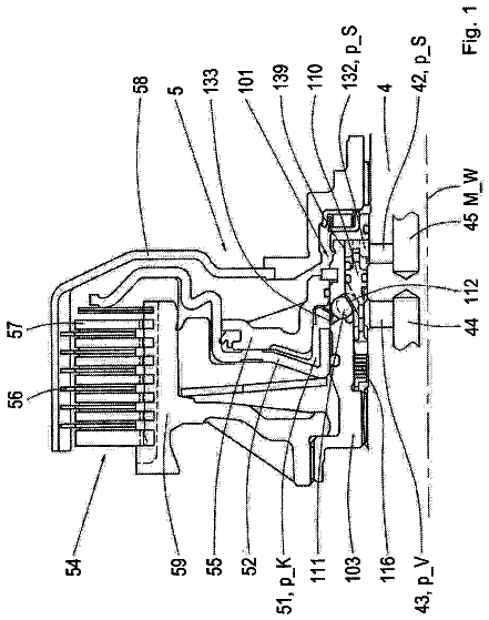
FIG. 5 is a perspective view of lever system 41 with lever 44 of FIG. 4 advantageously combined with lever actuator 58 . The illustrated combination simplifies the actuation of two partial clutches in a specific twin clutch to a considerable extent.
FIGS. 6 and 7 illustrate two Cartesian coordinate systems with x-axis 61 and y-axis 62 . Y-axis 62 shows the engagement or actuation force of a clutch that is actuated with the aid of a lever system as described above. X-axis 61 shows the associated actuating or engagement path.
The Cartesian coordinate system represents nominal characteristic lines 65 , 75 of the clutch. The dotted lines above and the dashed lines below nominal characteristic lines 65 , 75 of the clutch indicate maximum and minimum characteristic lines of the clutch.
The coordinate system shown in FIG. 6 illustrates characteristic map 68 of the lever system shown in FIG. 4 . The coordinate system shown in FIG. 7 indicates characteristic map 78 additionally factoring in a counter-spring such as counter-spring 25 shown in FIG. 2 .
Thus, it is seen that the objects of the present invention are efficiently obtained, although modifications and changes to the invention should be readily apparent to those having ordinary skill in the art, which modifications are intended to be within the spirit and scope of the invention as claimed. It also is understood that the foregoing description is illustrative of the present invention and should not be considered as limiting. Therefore, other embodiments of the present invention are possible without departing from the spirit and scope of the present invention.
List of reference symbols
1 Lever system 4 Lever 5 Pivot 8 Carriage 10 Double-headed arrow 11 Double-headed arrow 13 Line of action 14 Flexurally elastic region 16 Double-headed arrow 17 Double-headed arrow 18 Double-headed arrow 21 Lever system 24 Flexurally elastic region 25 Counter-spring 26 Double-headed arrow 27 Double-headed arrow 31 Lever system 34 Flexurally elastic region 41 Lever system 44 Lever 45 Pivot 48 Carriage 50 Base plate 51 Roller 52 Roller 53 Roller 55 Actuating contact region 56 Contact surface 57 Contact surface 58 Lever actuator 61 X axis 62 Y axis 65 Characteristic line 68 Characteristic map 75 Characteristic line 78 Characteristic map
 Lapsed, fee not paid7 drawings