Background of the invention
1. Field of the invention
The present invention relates to a liquid discharge apparatus and a method of conveying a medium, and more particularly, to a medium conveying technique of a liquid discharge apparatus that includes liquid discharge heads.
2. Description of the related art
An ink jet recording apparatus, which records a color image by using color ink, is known as a liquid discharge apparatus that includes liquid discharge heads using an ink jet system. The ink jet recording apparatus records a color image on a medium by discharging color ink to the medium from the liquid discharge heads using the ink jet system.
JP2006-103849A discloses an ink jet recording apparatus that includes a blower unit provided on the downstream side of liquid discharge heads in the conveying direction of a medium and performs processing for drying the medium by using the air sent from the blower unit.
Terms of “medium”, “liquid discharge head”, and “ink jet recording apparatus” correspond to terms of “recording medium”, “ink head”, and “image recording apparatus” of JP2006-103849A, respectively.
JP2011-168020A discloses an ink jet recording apparatus that includes a drawing section for recording an image on a medium and a drying processing section for performing processing for drying the medium on which the image is recorded. The ink jet recording apparatus disclosed in JP2011-168020A includes a blower unit, which is provided in the drying processing section at a position facing the outer peripheral surface of a drying cylinder for conveying the medium, and suppresses the occurrence of creases on the medium by using the air sent from the blower unit.
Terms of “medium”, “drawing section”, “drying processing section”, “drying cylinder”, and “blower unit” correspond to terms of “recording medium”, “image recording section”, “drying section”, “drying drum”, and “blower means” of JP2011-168020A, respectively.
JP2013-28140A discloses an ink jet recording apparatus using an impression cylinder conveying system. The ink jet recording apparatus disclosed in JP2013-28140A draws a color image on a medium by discharging color ink to the medium, which is conveyed by a drawing cylinder, from liquid discharge heads of a drawing section. The drawing cylinder includes grippers, which grip the front end of the medium, and conveys the medium while holding the medium on the outer peripheral surface thereof by suction.
Further, the ink jet recording apparatus disclosed in JP2013-28140A includes a drying section that is provided in the subsequent stage of the drawing section, and performs processing for drying the medium on which the color image is drawn. A chain gripper, which is provided with the grippers for gripping the front end of the medium, is applied to the conveyance of the medium in the drying section.
Terms of “medium”, “drawing cylinder”, “drawing section”, “liquid discharge head”, and “drying section” correspond to terms of “recording medium”, “image recording drum”, “image recording section”, “ink jet head”, and “ink drying processing section” of JP2013-28140A, respectively.
Summary of the invention
However, when the air sent from the blower unit flows into the drawing section of each of the ink jet recording apparatuses disclosed in JP2006-103849A and JP2011-168020A, dew condensation occurs on the discharge surfaces of the liquid discharge heads due to a difference between the temperature of the air sent from the blower unit and the temperature of the air, which is present around the discharge surfaces of the liquid discharge heads, and a difference between the humidity of the air sent from the blower unit and the humidity of the air that is present around the discharge surfaces of the liquid discharge heads.
That is, when high-temperature atmosphere continues to flow into the drawing cylinder, the temperature of the drawing cylinder rises. When the temperature of the drawing cylinder rises, a temperature difference is generated between the drawing cylinder and the discharge surfaces of the liquid discharge head. As a result, dew condensation occurs on the discharge surfaces of the liquid discharge heads.
Further, there is a concern that the rear end of the medium may fall on the side opposite to the outer peripheral surface of the drawing cylinder when the medium has passed from a suction-holding region of the drawing cylinder while the medium is delivered to the chain gripper of the drying processing section, which is disposed in the subsequent stage of the drawing section, from the drawing cylinder in the ink jet recording apparatus disclosed in JP2013-28140A.
It is possible to prevent the falling of the medium by sending the air to a delivery position of the medium between the drawing cylinder and the chain gripper so that the medium is positioned along the outer peripheral surface of the drawing cylinder. However, since the air, which is present around the drying processing section and of which the temperature and humidity are higher than those of the air present around the drawing section, is transported to the drawing section, dew condensation occurs on the discharge surfaces of the liquid discharge heads of the drawing section.
When dew condensation occurs on the discharge surfaces of the liquid discharge heads, there is a concern that the discharge performance of nozzle parts may change due to dew condensation. Further, there is a concern that the abnormal discharge of the nozzle parts may occur due to dew condensation.
The invention has been made in consideration of the above-mentioned circumstances, and an object of the invention is to provide a liquid discharge apparatus and a method of conveying a medium that suppress the occurrence of dew condensation on discharge surfaces of liquid discharge heads and achieve stable liquid discharge.
In order to achieve the above-mentioned object, a first aspect provides a liquid discharge apparatus comprising: a liquid discharge head that discharges liquid; a conveying section that supports and conveys a medium to which the liquid discharged from the liquid discharge head is to be applied; a blower unit that is disposed on the upstream side of the liquid discharge head in a medium conveying direction or the downstream side of the liquid discharge head in the medium conveying direction and suppresses the change of the posture of the medium by sending the air to the medium conveyed by the conveying section; a temperature adjusting section that is disposed on the downstream side of the blower unit in the medium conveying direction in a case in which the blower unit is disposed on the upstream side of the liquid discharge head in the medium conveying direction or is disposed on the upstream side of the blower unit in the medium conveying direction in a case in which the blower unit is disposed on the downstream side of the liquid discharge head in the medium conveying direction, and adjusts the temperature of an object, of which the temperature is to be adjusted, to a temperature higher than the ambient temperature of the liquid discharge head or a temperature lower than the ambient temperature of the liquid discharge head; and a blast control section that controls the operation of the blower unit. The blast control section sends an operation stop command, which stops an operation, or an air reduction command, which reduces the amount of the air to be sent, to the blower unit at a blast region-pass timing at which the medium to which the air is sent from the blower unit passes through a blast region of the blower unit.
According to the first aspect, the flowing of the air, which is present around the temperature adjusting section disposed on the side of the blower unit opposite to the liquid discharge head in the medium conveying direction, to the surrounding area of the liquid discharge head is suppressed. Accordingly, it is possible to prevent dew condensation that occurs on the discharge surface of the liquid discharge head due to a difference between the ambient temperature of the temperature adjusting section and the ambient temperature of the liquid discharge head and a difference between the humidity of the air present around the temperature adjusting section and the humidity of the air present around the liquid discharge head.
Further, since a change in the discharge characteristics of the liquid discharge head, which is caused by dew condensation occurring on the discharge surface of the liquid discharge head, is prevented, the abnormal discharge of the liquid discharge head is prevented. As a result, stable liquid discharge is achieved.
According to a second aspect, in the liquid discharge apparatus according to the first aspect, in a case in which a plurality of media are continuously conveyed, the blast control section applies a timing, at which the last medium of the plurality of media passes through the blast region of the blower unit, as the blast region-pass timing.
According to the second aspect, it is possible to stop the sending of the air from the blower unit or to reduce the amount of the air sent from the blower unit at an effective timing in a case in which media are continuously conveyed.
According to a third aspect, in the liquid discharge apparatus according to the first or second aspect, the blast control section applies a timing, at which a rear end of the medium to which the air is sent from the blower unit passes through the blast region, as the blast region-pass timing.
According to the third aspect, it is possible to stop the sending of the air from the blower unit or to reduce the amount of the air sent from the blower unit while reliably preventing the deformation of the medium, such as the falling of the medium and the turnover of the medium.
According to a fourth aspect, in the liquid discharge apparatus according to the first or second aspect, the blast control section applies a timing, at which a rear end of the medium to which the air is sent from the blower unit passes through a blast position of the blower unit, as the blast region-pass timing.
According to the fourth aspect, it is possible to stop the sending of the air from the blower unit or to reduce the amount of the air sent from the blower unit at an earlier timing.
According to a fifth aspect, in the liquid discharge apparatus according to the first or second aspect, the blast control section applies a timing, at which a part of the medium to which the air is sent from the blower unit passes through the blast region and the previously obtained shape of the medium during the conveyance of the medium is maintained, as the blast region-pass timing.
According to the fifth aspect, it is possible to stop the sending of the air from the blower unit or to reduce the amount of the air sent from the blower unit early while reliably preventing the deformation of a sheet, such as the falling of the medium and the turnover of the medium.
According to a sixth aspect, in the liquid discharge apparatus according to any one of the first to fifth aspects, the blast control section sends an operation start command to the blower unit at a blast region-reaching timing at which the medium to which the air is sent from the blower unit reaches the blast region of the blower unit.
According to the sixth aspect, deformation, such as falling or turnover, of the medium having passed through the blast region of the blower unit is prevented.
According to a seventh aspect, in the liquid discharge apparatus according to any one of the first to sixth aspects, in a case in which a plurality of media are continuously conveyed, the blast control section applies a timing, at which the first medium of the plurality of media reaches the blast region of the blower unit, as the blast region-pass timing.
According to the seventh aspect, it is possible to start the sending of the air from the blower unit at an effective timing in a case in which media are continuously conveyed.
According to an eighth aspect, in the liquid discharge apparatus according to the sixth or seventh aspect, the blast control section sends an operation start command to the blower unit at a blast region-reaching timing at which a front end of the medium to which the air is sent from the blower unit reaches the blast region of the blower unit.
According to the eighth aspect, since the air is sent to a medium at an earlier timing, it is possible to more reliably prevent the deformation of the medium.
According to a ninth aspect, in the liquid discharge apparatus according to the sixth or seventh aspect, the blast control section sends an operation start command to the blower unit at a blast region-reaching timing at which a rear end of the medium to which the air is sent from the blower unit reaches the blast region of the blower unit.
According to the ninth aspect, since the operation of the blower unit is started at a later timing while the deformation of a medium is prevented, the sending of the air, which is present around the temperature adjusting section, to the surrounding area of the discharge surface of the liquid discharge head is prevented by the air sent from the blower unit.
According to a tenth aspect, in the liquid discharge apparatus according to the sixth or seventh aspect, the blast control section sends an operation start command to the blower unit at a blast region-reaching timing that is a timing at which a part of the medium to which the air is sent from the blower unit reaches the blast region of the blower unit and the previously obtained shape of the medium during the conveyance of the medium is not maintained.
According to the tenth aspect, since the start of the operation of the blower unit is delayed as much as possible while the deformation of a medium is prevented, the sending of the air, which is present around the temperature adjusting section, to the surrounding area of the discharge surface of the liquid discharge head is prevented by the air sent from the blower unit.
According to an eleventh aspect, in the liquid discharge apparatus according to any one of the first to tenth aspects, the conveying section comprises a gripping part that grips one end of the medium conveyed by the conveying section to fix the medium.
According to the eleventh aspect, it is possible to prevent the deformation of a medium, such as the falling or turnover of a portion of a medium that is not gripped by the gripping part.
According to a twelfth aspect, in the liquid discharge apparatus according to any one of the first to eleventh aspects, the conveying section comprises a suction-fixing unit that sucks the surface of the medium, which is opposite to the surface of the medium to which the liquid discharged from the liquid discharge head is to be applied, to fix the medium.
According to the twelfth aspect, it is possible to prevent the deformation of a medium, such as the falling or turnover of a medium of which the suction performed by the suction-fixing unit is released.
According to a thirteenth aspect, in the liquid discharge apparatus according to any one of the first to twelfth aspects, the conveying section comprises a first conveying unit and a second conveying unit that is disposed on the downstream side of the first conveying unit in the conveying direction, and the blower unit is disposed at a position where a medium delivery region in which a medium is delivered to the second conveying unit from the first conveying unit is included in the blast region of the blower unit.
According to the thirteenth aspect, it is possible to prevent the deformation of a medium, such as the falling or turnover of a medium.
According to a fourteenth aspect, in the liquid discharge apparatus according to the thirteenth aspect, the liquid discharge head is disposed on a conveying path of a medium conveyed by the first conveying unit, and the temperature adjusting section is disposed at a position where the temperature adjusting section adjusts the temperature of the medium conveyed by the second conveying unit.
According to the fourteenth aspect, deformation, such as the falling or turnover, of a medium, which occurs when the medium is delivered to the second conveying unit from the first conveying unit, is prevented and the transport of the air, which is present around the temperature adjusting section disposed on the conveying path of a medium conveyed by the second conveying unit, to the surrounding area of the discharge surface of the liquid discharge head, which is disposed on the conveying path of the first conveying unit, is prevented.
According to a fifteenth aspect, in the liquid discharge apparatus according to the thirteenth or fourteenth aspect, the second conveying unit is disposed at a position where the conveying path of a medium of the second conveying unit is different from the conveying path of a medium of the first conveying unit in a vertical direction.
According to the fifteenth aspect, even in an aspect in which a medium is conveyed along the vertical direction where the falling of the medium easily occurs when the medium is conveyed to the second conveying unit from the first conveying unit, deformation, such as the falling or turnover of the medium, is prevented and the transport of the air, which is present around the temperature adjusting section, to the surrounding area of the discharge surface of the liquid discharge head is prevented.
According to a sixteenth aspect, in the liquid discharge apparatus according to any one of the thirteenth to fifteenth aspects, the first conveying unit is an impression cylinder that has a cylindrical shape, supports a medium by an outer peripheral surface thereof, and rotates and conveys the medium, comprises a first gripping part that grips one end of the medium to fix the medium, and includes a conveying path along which the medium is conveyed to the lower side in the vertical direction from the upper side in the vertical direction at a delivery position of the medium between itself and the second conveying unit.
According to the sixteenth aspect, the deformation of a medium, such as the falling or turnover of the medium, which occurs when the medium is delivered to the second conveying unit provided in the subsequent stage from the impression cylinder, is prevented.
According to a seventeenth aspect, in the liquid discharge apparatus according to any one of the thirteenth to sixteenth aspects, the second conveying unit comprises a second gripping part that grips at least one end of the medium conveyed by the second conveying unit to fix the medium, and the blower unit is disposed at a position where the blower unit sends the air to the first conveying unit from the second conveying unit.
According to the seventeenth aspect, the deformation of a medium, such as the falling or turnover of the medium, which occurs when the medium is delivered to the second conveying unit provided in the subsequent stage of the impression cylinder from the impression cylinder, is prevented.
According to an eighteenth aspect, in the liquid discharge apparatus according to any one of the thirteenth to seventeenth aspects, the temperature adjusting section includes a drying processing section that dries the medium to which the liquid discharged from the liquid discharge head is applied and performs processing for drying the medium conveyed by the second conveying unit.
According to the eighteenth aspect, the sending of high-temperature air, which is present around the drying processing section, to the surrounding area of the discharge surface of the liquid discharge head is prevented.
A nineteenth aspect provides a method of conveying a medium to which liquid discharged from a liquid discharge head, which discharges liquid, is to be applied. The method comprises: a blast step of sending the air to the medium to be conveyed from the upstream side of the liquid discharge head in a medium conveying direction or the downstream side of the liquid discharge head in the medium conveying direction; and a temperature adjusting step of adjusting the temperature of an object, of which the temperature is to be adjusted, to a temperature higher than the ambient temperature of the liquid discharge head or a temperature lower than the ambient temperature of the liquid discharge head on the downstream side of the sending of the air in the medium direction in a case in which the air is sent from the upstream side of the liquid discharge head in the medium conveying direction or on the upstream side of the sending of the air in the medium conveying direction in a case in which the air is sent from the downstream side of the liquid discharge head in the medium conveying direction. In the blast step, a blast stop command for stopping the sending of the air or an air reduction command for reducing the amount of the air to be sent is generated at a blast region-pass timing at which the medium to which the air is sent passes through a blast region.
In the nineteenth aspect, in a case in which a plurality of media are continuously conveyed, an aspect in which a timing, at which the last medium of the plurality of media passes through the blast region, is applied as the blast region-pass timing is preferable. Further, an aspect in which a timing at which the rear end of the medium to which the air is sent passes through the blast region is applied as the blast region-pass timing, an aspect in which a timing at which the rear end of the medium to which the air is sent passes through the blast position of the blower unit is applied as the blast region-pass timing, or an aspect in which a timing, at which a part of the medium to which the air is sent passes through the blast region and the previously obtained shape of the medium during the conveyance of the medium is maintained, is applied as the blast region-pass timing is preferable.
In the nineteenth aspect, an aspect in which a blast start command is sent at a blast region-reaching timing at which the medium to which the air is sent reaches the blast region is preferable. Further, in a case in which a plurality of media are continuously conveyed, an aspect in which a timing, at which the first medium of the plurality of media reaches the blast region, is applied as the blast region-pass timing is preferable.
In the nineteenth aspect, an aspect in which an operation start command is sent to the blower unit at the blast region-reaching timing at which the rear end of the medium to which the air is sent reaches the blast region, an aspect in which a blast start command is sent at the blast region-reaching timing at which the rear end of the medium to which the air is sent reaches the blast region of the blower unit, or an aspect in which a blast start command is sent at a blast region-reaching timing that is a timing at which a part of the medium to which the air is sent reaches the blast region and the previously obtained deformation of the medium does not occur is preferable.
In the nineteenth aspect, an aspect in which the medium is conveyed while one end of the medium is gripped, or an aspect in which the surface of the medium, which is opposite to the surface of the medium to which the liquid discharged from the liquid discharge head is to be applied, is sucked and the medium is fixed is preferable.
The nineteenth aspect can also be applied to an aspect which includes a first conveying step and a second conveying step of conveying a medium on the downstream side of a conveying path of the first conveying step in a conveying direction and in which the blast region includes a medium delivery region in which the medium is delivered to the second conveying step from the first conveying step.
The nineteenth aspect can also be applied to an aspect that includes a liquid discharge step of discharging liquid to a medium conveyed in the first conveying step and a temperature adjusting step of adjusting the temperature of a medium conveyed in the second conveying step.
The nineteenth aspect can also be applied to an aspect in which the conveying path of a medium of the second conveying step is different from the conveying path of a medium of the first conveying step in the vertical direction.
The nineteenth aspect can also be applied to an aspect in which the first conveying step rotates and conveys a medium while supporting the medium by an outer peripheral surface of an impression cylinder having a cylindrical shape and conveys the medium while gripping one end of the medium and the medium is delivered to the lower side in the vertical direction from the upper side in the vertical direction at a delivery position of the medium between the first conveying step and the second conveying step.
The nineteenth aspect can also be applied to an aspect in which the medium is conveyed while at least one end of the medium is gripped in the second conveying step and the air is sent to the conveying path of the first conveying step from the conveying path of the second conveying step.
The nineteenth aspect can also be applied to an aspect that includes a drying processing step of performing processing for drying the medium, which is conveyed in the second conveying step, as the temperature adjusting step.
According to the liquid discharge apparatus, the flowing of the air, which is present around the temperature adjusting section disposed on the side of the blower unit opposite to the liquid discharge head in the medium conveying direction, to the surrounding area of the liquid discharge head is suppressed. Accordingly, it is possible to prevent dew condensation that occurs on the discharge surface of the liquid discharge head due to a difference between the ambient temperature of the temperature adjusting section and the ambient temperature of the liquid discharge head and a difference between the humidity of the air present around the temperature adjusting section and the humidity of the air present around the liquid discharge head.
Further, since a change in the discharge characteristics of the liquid discharge head, which is caused by dew condensation occurring on the discharge surface of the liquid discharge head, is prevented, the abnormal discharge of the liquid discharge head is prevented. As a result, stable liquid discharge is achieved.
Brief description of the drawings
FIG. 1 is a view showing the overall configuration of an ink jet recording apparatus according to an embodiment of the invention.
FIG. 2 is a block diagram showing the schematic configuration of a control system of the ink jet recording apparatus shown in FIG. 1 .
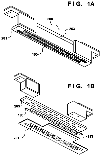
FIG. 3 is a plan perspective view of discharge surfaces that shows an example of the structure of a liquid discharge head shown in FIG. 1 .
FIG. 4 is a cross-sectional view showing the internal structure of the liquid discharge head shown in FIG. 3 .
FIG. 5 is a plan perspective view of the discharge surface 277 of the head module 200 shown in FIG. 4 .
FIG. 6 is a cross-sectional view showing the internal structure of the liquid discharge head shown in FIG. 3 .
FIG. 7 is an enlarged view of FIG. 1 that shows the disposition of a blower unit.
FIG. 8 is a perspective view showing an example of the structure of the blower unit.
FIG. 9 is a perspective view showing another example of the structure of the blower unit.
FIG. 10 is a perspective view showing still another example of the structure of the blower unit.
FIG. 11 is a perspective view showing still another example of the structure of the blower unit.
(A) of FIG. 12 is a schematic diagram showing the operating period of the blower unit, (B) of FIG. 12 is a schematic diagram showing an output signal of a sheet sensor, (C) of FIG. 12 is a schematic diagram showing a command signal that indicates the start of the operation of the blower unit, and (D) of FIG. 12 is a schematic diagram showing a command signal that indicates the stop of the operation of the blower unit.
(A) of FIG. 13 is a schematic diagram showing the operating period of the blower unit during the continuous feeding of sheets, (B) of FIG. 13 is a schematic diagram showing an output signal of the sheet sensor during the continuous feeding of sheets, (C) of FIG. 13 is a schematic diagram showing a command signal that indicates the start of the operation of the blower unit during the continuous feeding of sheets, and (D) of FIG. 13 is a schematic diagram showing a command signal that indicates the stop of the operation of the blower unit during the continuous feeding of sheets.
FIG. 14 is a view illustrating the timing of an operation start command for the blower unit and the timing of an operation stop command for the blower unit.
FIG. 15A is a schematic diagram showing a timing at which a front end of a sheet passes through a starting end of a blast region of the blower unit, FIG. 15B is a schematic diagram showing a timing at which a rear end of the sheet passes through the starting end of the blast region of the blower unit, and FIG. 15C is a schematic diagram showing a timing at which a part of the sheet passes through a terminus of the starting end of the blast region of the blower unit.
FIG. 16 is a schematic diagram showing an example of the falling of a sheet.
FIG. 17 is a schematic diagram showing another example of the falling of a sheet.
FIG. 18A is a schematic diagram showing a timing at which a part of a sheet passes through a starting end of a blast region of the blower unit, FIG. 18B is a schematic diagram showing a timing at which a rear end of the sheet passes through the blast position of the blower unit, and FIG. 18C is a schematic diagram showing a timing at which the rear end of the sheet passes through a starting end of a conveying guide.
FIG. 19 is a flowchart illustrating the flow of the operation control of the blower unit.
FIG. 20 is a diagram illustrating tables that are applied to the operation control of the blower unit.
FIG. 21 is a view showing the overall configuration of an ink jet recording apparatus according to a first modification example.
FIG. 22 is a plan view showing the arrangement of a blower unit and a temperature adjusting section of the ink jet recording apparatus shown in FIG. 21 .
FIG. 23 is a plan view showing another example of the arrangement of the blower unit and the temperature adjusting section shown in FIG. 22 .
FIG. 24 is a view showing the overall configuration of an ink jet recording apparatus according to a second modification example.
FIG. 25 is a plan view showing the arrangement of a blower unit and a temperature adjusting section of the ink jet recording apparatus shown in FIG. 24 .
FIG. 26 is a plan view showing another example of the arrangement of the blower unit and the temperature adjusting section of the ink jet recording apparatus shown in FIG. 24 .
Description of the preferred embodiments
A preferred embodiment of the invention will be described in detail below with reference to accompanying drawings.
[Overall Configuration of Ink Jet Recording Apparatus]
FIG. 1 is a view showing the overall configuration of an ink jet recording apparatus according to an embodiment of the invention.
An ink jet recording apparatus 10 shown in FIG. 1 is an ink jet recording apparatus that draws an image on a sheet S with ink by an ink jet system. The ink jet recording apparatus 10 is an aspect of a liquid discharge apparatus that discharges liquid to a sheet S functioning as a medium.
The ink jet recording apparatus 10 mainly includes a sheet feeding section 12 that feeds a sheet S, a treatment liquid applying section 14 , a treatment liquid drying processing section 16 , a drawing section 18 , an ink drying processing section 20 , and a sheet discharge section 24 . The treatment liquid applying section 14 applies treatment liquid to the sheet S fed from the sheet feeding section 12 . The treatment liquid drying processing section 16 performs processing for drying the sheet S to which treatment liquid is applied by the treatment liquid applying section 14 . The drawing section 18 records an image on the image recording of the sheet S, which has been subjected to drying processing by the treatment liquid drying processing section 16 , with ink by an ink jet system. The ink drying processing section 20 performs processing for drying the sheet S on which the image is recorded by the drawing section 18 . The sheet discharge section 24 discharges the sheet S that has been subjected to drying processing by the ink drying processing section 20 .
The ink drying processing section 20 functions as a temperature adjusting section that adjusts the temperature of an object, of which the temperature is to be adjusted, to a temperature higher than the ambient temperature of the discharge surface of a liquid discharge head. The ambient temperature of the discharge surface is a temperature in the range where dew condensation on the discharge surface occurs.
[Sheet Feeding Section]
the sheet feeding section 12 mainly includes a sheet feeding stand 30 , a sucker device 32 , a pair of sheet feed rollers 34 , a feeder board 36 , a stopper 38 , and a sheet feeding cylinder 40 . The sheet feeding section 12 feeds sheets S, which are loaded on the sheet feeding stand 30 , to the treatment liquid applying section 14 one by one.
The sheets S loaded on the sheet feeding stand 30 are sequentially lifted from the top thereof one by one by the sucker device 32 , and are fed to the pair of sheet feed rollers 34 . The sheets S, which are fed to the pair of sheet feed rollers 34 , are placed on the feeder board 36 and are conveyed by the feeder board 36 .
The sheet S is pushed against the conveying surface of the feeder board 36 by retainers 36 A and a guide roller 36 B, so that the irregularities of the sheet S are corrected. When the front end of the sheet S comes into contact with the stopper 38 , the inclination of the sheet S is corrected. The sheet S, which is conveyed by the feeder board 36 , is delivered to the sheet feeding cylinder 40 .
While the front end portion of the sheet S, which is delivered to the sheet feeding cylinder 40 , is gripped by a gripper 40 A of the sheet feeding cylinder 40 , the sheet S is conveyed to the treatment liquid applying section 14 . The details of the gripper 40 A are not shown.
The gripper 40 A includes a plurality of claws that are arranged along the axial direction of the sheet feeding cylinder 40 and a claw stand that is disposed at a position facing the plurality of claws. The gripper 40 further includes a gripper shaft supporting the plurality of claws so that the plurality of claws can oscillate.
The plurality of claws are oscillated by the rotation of the gripper shaft of the gripper 40 A, so that the gripper 40 A is opened and closed. The arrangement of the plurality of claws is determined depending on the size of the sheet S.
[Treatment Liquid Applying Section]
The treatment liquid applying section 14 mainly includes a treatment liquid cylinder 42 that conveys a sheet S and a treatment liquid applying device 44 that applies predetermined treatment liquid to the image recording surface of the sheet S conveyed by the treatment liquid cylinder 42 . The treatment liquid applying section 14 applies treatment liquid to the image recording surface of the sheet S.
The treatment liquid applied to the sheet S has a function to flocculate color materials, which are contained in the ink discharge to the sheet S by the drawing section 18 provided in the subsequent stage, or a function to insolubilize the color materials of the ink. Since the treatment liquid is applied to the sheet S and ink is then discharged to the sheet, high-quality printing can be performed without the occurrence of impact interference and the like even though a general-purpose sheet is used.
A term of “discharging” of this specification can be replaced with jetting or recording.
The sheet S, which is delivered from the sheet feeding cylinder 40 of the sheet feeding section 12 , is delivered to the treatment liquid cylinder 42 . The treatment liquid cylinder 42 grips the front end of the sheet S by a gripper 42 A, and holds the sheet S on the outer peripheral surface by suction.
Since the same structure as the gripper 40 A of the sheet feeding cylinder 40 can be applied to the gripper 42 A, the description of the gripper 42 A will be omitted.
When the treatment liquid cylinder 42 is rotated while the front end portion of the sheet S is gripped by the gripper 42 A and the sheet S is held on the outer peripheral surface of the treatment liquid cylinder 42 , the sheet S is conveyed while being wound on the outer peripheral surface of the treatment liquid cylinder 42 . Treatment liquid is applied to the sheet S, which is conveyed to the treatment liquid cylinder 42 , from the treatment liquid applying device 44 .
Coating using a coating roller, coating using a blade, or the like can be used as an example of the form of application. Discharge using an ink jet system, spraying using a spray system, or the like can be used as another example of the form of application.
[Treatment Liquid Drying Processing Section]
The treatment liquid drying processing section 16 mainly includes a treatment liquid drying processing cylinder 46 , sheet conveying guides 48 , and a treatment liquid drying processing unit 50 . The treatment liquid drying processing section 16 performs processing for drying the sheet S to which treatment liquid is applied. The treatment liquid drying processing cylinder 46 conveys the sheet S. The sheet conveying guides 48 support the sheet S that is conveyed by the treatment liquid drying processing cylinder 46 . The treatment liquid drying processing unit 50 dries the sheet S, which is conveyed by the treatment liquid drying processing cylinder 46 , by blowing hot air to the sheet S.
A treatment liquid drying cylinder blower unit 51 , which sends the air to the delivery position of the sheet S to be delivered to the treatment liquid drying processing cylinder 46 from the treatment liquid cylinder 42 , is disposed in the treatment liquid drying processing cylinder 46 .
The front end of the sheet S, which is delivered to the treatment liquid drying processing cylinder 46 from the treatment liquid cylinder 42 of the treatment liquid applying section 14 , is gripped by a gripper 46 A of the treatment liquid drying processing cylinder 46 . Since the same structure as the gripper 40 A of the sheet feeding cylinder 40 can be applied to the gripper 46 A, the description of the gripper 46 A will be omitted.
The surface of the sheet S opposite to the surface of the sheet S coated with treatment liquid is supported by the sheet conveying guides 48 in a state in which the surface of the sheet S coated with treatment liquid faces inside. When the treatment liquid drying processing cylinder 46 is rotated, the sheet S is conveyed while being wound on the outer peripheral surface of the treatment liquid drying processing cylinder 46 .
Hot air is sent to the sheet S, which is conveyed by the treatment liquid drying processing cylinder 46 , from the treatment liquid drying processing unit 50 disposed in the treatment liquid drying processing cylinder 46 , so that the sheet S is subjected to drying processing. When the sheet S is subjected to drying processing, a solvent component contained in the treatment liquid applied to the sheet S is removed and a treatment liquid layer is formed on the surface of the sheet S to which the treatment liquid is applied.
[Image Recording Section]
The description continues in the full USPTO document.
 Lapsed, fee not paid16 drawings

