Lapsed, fee not paid8 drawings
Industrial Equipment · US 9,724,902 B2
Air-sealed body capable of automatically opening air valve
An air-sealed body capable of automatically opening an air valve is provided.
US 9,724,908 B2 · Assignee: The Procter & Gamble Company · Inventors: Byrne; Thomas Timothy et al.
Sheet 1 of 42 from the published document. All sheets in the USPTO PDF
A method for printing 7 or more inks on a substrate. The method can include the steps of: providing a substrate; providing 7 or more inks; and providing a print system, the print system comprising 6 or less rotating rolls. Each of the 6 or less rotating rolls can be disposed in an operative relationship to transport at least one of the 7 or more inks to a vascular network in one of 6 or less rotating rolls. The method includes contacting the substrate with the at least one of the 7 or more inks.
Manufacturers of consumer goods often apply colors or performance fluids (such as lotion, adhesives, softeners and the like) to their products. For example, paper towel, toilet tissue, and/or facial tissue products often incorporate printed patterns, softening agents and the like. Likewise, the packaging for consumer products (e.g., films, cardboards, etc.) incorporate printed patterns or performance fluids. To date, manufacturers have mostly relied on a single printing apparatus, such as roll, to apply a single fluid. Moreover, manufacturers are plagued with challenges related to their inability to precisely control fluid flow and application at high processing rates. Manufacturers may use moving rolls having primarily axial fluid flow and/or primarily circumferential fluid flow which results in uneven fluid distribution and lack of fluid reaching parts of the rolls. In addition, such d
1 of 42 drawing sheets so far from the published document, cropped to the drawing. Every sheet is in the USPTO PDF.
What the patent claimed, word for word. All of it is now free to use.
The present invention relates to equipment and methods for depositing a fluid or a plurality of fluids onto a substrate. More particularly, the invention relates to equipment and methods for printing fluids on moving substrates.
Manufacturers of consumer goods often apply colors or performance fluids (such as lotion, adhesives, softeners and the like) to their products. For example, paper towel, toilet tissue, and/or facial tissue products often incorporate printed patterns, softening agents and the like. Likewise, the packaging for consumer products (e.g., films, cardboards, etc.) incorporate printed patterns or performance fluids. To date, manufacturers have mostly relied on a single printing apparatus, such as roll, to apply a single fluid. Moreover, manufacturers are plagued with challenges related to their inability to precisely control fluid flow and application at high processing rates. Manufacturers may use moving rolls having primarily axial fluid flow and/or primarily circumferential fluid flow which results in uneven fluid distribution and lack of fluid reaching parts of the rolls. In addition, such designs limit the number and sizes of fluid channels that may be incorporated into the device and limit the location of the fluid orifices stemming from those channels in a way that undermines precision. Alternatively, manufacturers use printing plates and flat surfaces, which result in slower processing or imprecision when running at high rates as the printing plate may not be able to keep up with the moving substrate.
Known devices also suffer from imprecise registration, overlaying and blending of fluids. Because a single device is often used for a single fluid, registration, overlaying, and blending between multiple fluids requires the use of more than one device. The inherent imprecision in each known device results in imprecision when trying to register (etc.) their respective fluids. Indeed, because the inability to control fluid flow and application and other factors in each device, known devices often are not able to precisely register fluids with other fluids or product features such as embossments or sealing areas.
Further, manufacturers are faced with higher production costs and resources due to their inability to separately control different fluids in one printing device.
Therefore, there is a need for an apparatus for depositing more than one fluid on a substrate. Further, there is a need for a controllable and/or customizable apparatus for depositing fluid(s) that permits more precise fluid deposition. Further still, there is a need for an efficient process for, and decreased manufacturing costs associated with, depositing one or more fluids on a substrate.
A method for printing 7 or more inks on a substrate is disclosed. The method can include the steps of: providing a substrate; providing 7 or more inks; providing a print system, the print system comprising 6 or less rotating rolls, each of the 6 or less rotating rolls disposed in operative relationship with the substrate and each rotating roll comprising: a central longitudinal axis and an exterior surface wherein the rotating roll rotates about the central longitudinal axis and the exterior surface defines an interior region and substantially surrounds the central longitudinal axis, a vascular network configured to supply at least one of the 7 or more inks from the interior region of the rotating roll to the exterior surface of the rotating roll in a predetermined path, wherein the vascular network comprises at least one main artery, at least one capillary and a plurality of fluid exits on the exterior surface, wherein: the at least one main artery comprises an inlet and is substantially parallel to the central longitudinal axis of the rotating roll, wherein the at least one of the 7 or more inks enters the vascular network at the inlet; and wherein the at least one capillary is attached to the at least one main artery and is in fluid communication with the at least one main artery and at least two fluid exits through a substantially radial fluid path to form a tree; transporting at least one of the 7 or more inks to one of the vascular networks in one of the 6 or less rotating rolls; and contacting the substrate with the at least one of the 7 or more inks.
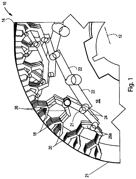
FIG. 1 is a perspective view of a rotating roll in accordance with one embodiment of the present invention;
FIG. 2 is a partial perspective view of a rotating roll and vascular network in accordance with one embodiment of the present invention;
FIG. 2A is a partial perspective view of a rotating roll and vascular network in accordance with one embodiment of the present invention with a nonlimiting example of a tree encircled;
FIG. 3 is a partial perspective view of a rotating roll and vascular network in accordance with one embodiment of the present invention;
FIG. 4 is a schematic view of a rotating roll and main artery in accordance with one embodiment of the present invention;
FIG. 5 is a partial perspective view of a rotating roll and vascular network in accordance with one embodiment of the present invention;
FIG. 6 is a schematic representation of the interior region of a rotating roll in accordance with one embodiment of the present invention;
FIG. 7 is a schematic representation of an exemplary tree in a vascular network in accordance with one embodiment of the present invention;
FIG. 7A is a schematic representation of another exemplary tree in a vascular network in accordance with one embodiment of the present invention;
FIG. 8 is a schematic representation of a rotating roll and vascular network in accordance with one embodiment of the present invention;
FIGS. 9A-9E are schematic representations of fluid exits and channels in accordance with nonlimiting examples of the present invention;
FIGS. 10A-10C are schematic representations of fluid exits in accordance with nonlimiting examples of the present invention;
FIGS. 11A-11D are schematic representations of fluid exits in accordance with nonlimiting examples of the present invention;
FIG. 12 is a schematic representation of one nonlimiting example of a micro-reservoir in accordance with the present invention;
FIGS. 13A-13C are schematic representations of micro-reservoirs in accordance with nonlimiting examples of the present invention;
FIG. 14 is a partial, front elevational view of a rotating roll and vascular network in accordance with one nonlimiting embodiment of the present invention;
FIG. 15 is a schematic representation of a rotating roll and vascular network in accordance with one embodiment of the present invention;
FIG. 16 is a schematic representation of fluid exits in accordance with one embodiment of the present invention;
FIG. 17 is a schematic representation of an interior region of a rotating roll in accordance with one embodiment of the present invention;
FIG. 18 is a schematic representation of a rotating roll in accordance with one embodiment of the present invention;
FIG. 19 is a schematic representation of a rotating roll in accordance with one embodiment of the present invention;
FIG. 20 is a schematic representation of a plurality of rotating rolls in accordance with one embodiment of the present invention;
FIG. 21 is a schematic representation of a rotating roll and substrate in accordance with one embodiment of the present invention;
FIG. 22 is a schematic representation of a print system in accordance with one embodiment of the present invention;
FIG. 23 is a schematic representation of a print system in accordance with another embodiment of the present invention;
FIG. 24 is a schematic representation of a print system in accordance with yet another embodiment of the present invention;
FIG. 25 is a perspective view of a rotating roll and sleeve in accordance with one embodiment of the present invention;
FIG. 26 is a perspective view of a rotating roll and sleeve in accordance with one embodiment of the present invention;
FIG. 27 is a schematic representation of a sleeve in accordance with one embodiment of the present invention;
FIG. 28 is a schematic representation of a rotating roll and sleeve in accordance with an embodiment of the present invention;
FIG. 29 is a schematic representation of a rotating roll, a sleeve and sleeve exits in accordance with nonlimiting examples of the present invention;
FIG. 30 is a partial, perspective view of a rotating roll in accordance with an embodiment of the present invention;
FIGS. 31A-31B are schematic representations of exemplary trees in accordance with nonlimiting examples of the present invention;
FIG. 32 is a schematic representation of trees in accordance with one nonlimiting example of the present invention;
FIGS. 33A-33E are charts depicting phenomena resulting from a vascular network designed in accordance with one nonlimiting example of the present invention;
FIGS. 34A-34E are charts depicting phenomena resulting from a vascular network designed in accordance with one nonlimiting example of the present invention;
FIG. 35 is a schematic representation of a sleeve and roll system in accordance with one embodiment of the present invention;
FIG. 36 is a schematic representation of a sleeve and roll system in accordance with an alternative embodiment of the present invention;
FIG. 37 is a schematic representation of a rotating roll and backing surface in accordance with one embodiment of the present invention;
FIG. 38 is a schematic representation of a rotating roll and backing surface in accordance with another embodiment of the present invention;
FIG. 39 is a schematic representation of a rotating roll used in conjunction with ancillary parts in accordance with one embodiment of the present invention;
FIG. 40 is a schematic representation of a method in accordance with one embodiment of the present invention;
FIG. 41 is a schematic representation of a method in accordance with one embodiment of the present invention;
FIG. 42 is a schematic representation of a method in accordance with one embodiment of the present invention;
FIG. 43 is a schematic representation of a method in accordance with one embodiment of the present invention; and
FIG. 44 is a schematic representation of a method in accordance with one embodiment of the present invention. DETAILED DESCRIPTION OF THE INVENTION Definitions
As used herein, the “aspect ratio” of a shape is the ratio of the length of the longest dimension or diameter of the shape, in any direction, that intersects the shape's midpoint and length of the shortest dimension or diameter of the shape, in any direction, that intersects the shape's midpoint.
“Vascular network” as used herein means a network of channels that carry fluid from an entry, such as an inlet, to one or more exits. The channels include one or more main arteries, one or more capillaries, and/or one or more sub-capillaries. In the vascular network, each channel may be in fluid communication with another channel. In general, the entry may be at or near the main artery, and the main artery may be in direct fluid communication (i.e., without intermediate channels) with a capillary. Likewise, a capillary may be in direct fluid communication with a main artery, another capillary, and/or a sub-capillary, and/or a fluid exit (all of which are discussed more fully below). Capillaries may extend from a main artery and connect with a sub-capillary or divide into a series of sub-capillaries. In one embodiment, the cross-sectional area of a main artery is larger than that of a capillary to which the main artery is connected. In another embodiment, the cross-sectional area of a capillary is larger than that of a sub-capillary to which the capillary is connected. In some respects, the vascular network of the present invention is analogous to a biological vascular network. However, the vascular network of the present invention is not a biological system.
In an embodiment, one path from the entry to an exit is substantially radial. In other words, the vascular network carries a fluid in a substantially radial direction.
“Radial” or “radially” as used herein refers to the direction of radii in a circular, spherical, cylindrical or similar shaped object. In other words, if an element is described as extending radially herein, that element extends from an inner portion (including the center) of an object outward to an external portion, including the perimeter or outer boundary or surface of that object. Radial and radially as used herein are distinguished from circumferentially, wherein an element so described would extend about the center of a spherical, cylindrical or similar shaped object such that the element would mimic the circumference or perimeter of the object. Likewise, radial and radially is distinguished from axially, wherein an element so described would extend in a direction parallel or substantially parallel to the longitudinal axis of the object.
Elements described as extending “substantially radially” or being “substantially radial” may have axial or circumferential components. However, a substantially radial element as described herein means that the element has a radial vector greater than its axial or circumferential vectors. Visually, in the aggregate, a substantially radial element (which may be a tree 23 or a fluid path 48 ) extends in a radial direction more than it extends in an axial or circumferential manner.
“Fluid” as used herein means a substance, as a liquid or gas, that is capable of flowing and that changes its shape at a steady rate when acted upon by a force tending to change its shape. Exemplary fluids suitable for use with the present disclosure include inks; dyes; emulsions such as oil and water emulsions; softening agents; cleaning agents; dermatological solutions; wetness indicators; adhesives; botanical compounds (e.g., described in U.S. Patent Publication No. US 2006/0008514); skin benefit agents; medicinal agents; lotions; fabric care agents; dishwashing agents; carpet care agents; surface care agents; hair care agents; air care agents; actives comprising a surfactant selected from the group consisting of: anionic surfactants, cationic surfactants, nonionic surfactants, zwitterionic surfactants, and amphoteric surfactants; antioxidants; UV agents; dispersants; disintegrants; antimicrobial agents; antibacterial agents; oxidizing agents; reducing agents; handling/release agents; perfume agents; perfumes; scents; oils; waxes; emulsifiers; dissolvable films; edible dissolvable films containing drugs, pharmaceuticals and/or flavorants. Suitable drug substances can be selected from a variety of known classes of drugs including, for example, analgesics, anti-inflammatory agents, anthelmintics, antiarrhythmic agents, antibiotics (including penicillin), anticoagulants, antidepressants, antidiabetic agents, antipileptics, antihistamines, antihypertensive agents, antimuscarinic agents, antimycobacterial agents, antineoplastic agents, immunosuppressants, antithyroid agents, antiviral agents, anxiolytic sedatives (hypnotics and neuroleptics), astringents, beta-adrenoceptor blocking agents, blood products and substitutes, cardiac inotropic agents, corticosteroids, cough suppressants (expectorants and mucolytics), diagnostic agents, diuretics, dopaminergics (antiparkinsonian agents), haemostatics, immunological agents, lipid regulating agents, muscle relaxants, parasympathomimetics, parathyroid calcitonin and biphosphonates, prostaglandins, radiopharmaceutical, sex hormones (including steroids), anti-allergic agents, stimulants and anorexics, sympathomimetics, thyroid agents, PDE IV inhibitors, NK3 inhibitors, CSBP/RK/p38 inhibitors, antipsychotics, vasodilators and xanthines; and combinations thereof.
“Register” as used herein means to spatially align an article, including but not limited to a fluid, with another article, such as another fluid, or with a particular area or feature of a substrate.
“Overlay” as used herein means to place a fluid on top of another fluid. For example, a blue fluid may overlay a yellow fluid, producing a green image.
“Blend” as used herein means to place fluids, such as inks of different shades, close to one another, such that the fluids visually appear to mix (creating a different shade or hue in the case of inks).
“Operative relationship” as used herein in reference to fluid transmission between two articles (e.g., a roll and a substrate) means that the articles are disposed such that the fluid is transmitted through actual contact between the articles, close proximity of the articles and/or other suitable means for the fluid to be deposited.
“Paper product,” as used herein, refers to any formed, fibrous structure product, traditionally, but not necessarily, comprising cellulose fibers. In one embodiment, the paper products of the present invention include sanitary tissue products. A paper product may be made by a process comprising the steps of forming an aqueous papermaking furnish, depositing this furnish on a foraminous surface, such as a Fourdrinier wire, and removing the water from the furnish (e.g., by gravity or vacuum-assisted drainage), forming an embryonic web, transferring the embryonic web from the forming surface to a transfer surface traveling at a lower speed than the forming surface. The web is then transferred to a fabric upon which it is dried to a final dryness after which it is wound upon a reel. Paper products may be through-air-dried.
“Product feature” as used herein means structural or design features that are applied to or formed on a substrate prior to or after use of the apparatuses or methods described herein. Product features may include, for example, embossments, wet-formed textures, addition of fibers such as by flocking, apertures, perforations, printing, registration marks and/or other fluid deposits.
“Micro-reservoir” as used herein means a structure having a void volume capable of collecting and/or holding less than about 1000 mm.sup.3, or less than 512 mm.sup.3, or less than 125 mm.sup.3, or less than 75 mm.sup.3, or less than 64 mm.sup.3, or less than 50 mm.sup.3 of one or more fluids and supplying the fluids to one or more exits. In one nonlimiting example, the micro-reservoir operates as a reverse funnel, being smaller in the area where fluid enters the micro-reservoir than the area where the fluid leaves the micro-reservoir. The micro-reservoir can serve as a single fluid supply region for one or more fluid exits or sleeve exits (both types of exits described in more detail below), minimizing the number of channels required to supply a given number of exits. In addition, the micro-reservoir may be disposed under an exterior surface or a sleeve.
“Sanitary tissue product” as used herein means one or more fibrous structures, converted or not, that is useful as a wiping implement for post-urinary and post-bowel movement cleaning (bath tissue), for otorhinolaryngological discharges (facial tissue and/or disposable handkerchiefs), and multi-functional absorbent and cleaning uses (absorbent towels and/or wipes). Sanitary tissue products used in the present invention may be single or multi-ply.
“Substrate” as used herein includes products or materials on which indicia or fluids may be deposited, imprinted and/or substantially affixed. Substrates suitable for use and within the intended scope of this disclosure include single or multi-ply fibrous structures, such as paper products like sanitary tissue products. Other materials are also intended to be within the scope of the present invention as long as they do not interfere or counteract any advantage presented by the instant invention. Suitable substrates may include films, foils, polymer sheets, cloth, wovens or nonwovens, paper, cellulose fiber sheets, co-extrusions, laminates, high internal phase emulsion foam materials, and combinations thereof. The properties of a selected material can include, though are not restricted to, combinations or degrees of being: porous, non-porous, microporous, gas or liquid permeable, non-permeable, hydrophilic, hydrophobic, hydroscopic, oleophilic, oleophobic, high critical surface tension, low critical surface tension, surface pre-textured, elastically yieldable, plastically yieldable, electrically conductive, and electrically non-conductive. Such materials can be homogeneous or composition combinations. Additionally, absorbent articles (e.g., diapers and catamenial devices) may serve as suitable substrates. In the context of absorbent articles in the form of diapers, printed web materials may be used to produce components such as backsheets, topsheets, landing zones, fasteners, ears, side panels, absorbent cores, and acquisition layers. Descriptions of absorbent articles and components thereof can be found in U.S. Pat. Nos. 5,569,234; 5,702,551; 5,643,588; 5,674,216; 5,897,545; and 6,120,489; and U.S. Patent Publication Nos. 2010/0300309 and 2010/0089264.
Substrates suitable for the present invention also include products suitable for use as packaging materials. This may include, but not be limited to, polyethylene films, polypropylene films, liner board, paperboard, carton materials, and the like.
Overview
FIG. 1 depicts a rotating roll 10 in accordance with one embodiment of the present invention. The rotating roll 10 may have a central longitudinal axis 12 , about which the roll 10 may rotate, an exterior surface 14 and an interior region 16 defined and bounded by the exterior surface 14 . The rotating roll 10 may further comprise a vascular network 18 of channels 20 for transmitting fluids from the interior region 16 of the roll 10 to the exterior surface 14 . Turning to FIG. 2 , the channels 20 may comprise a main artery 22 , capillaries 24 and sub-capillaries 26 . The main artery 22 may be associated with one or more capillaries 24 which extend from the main artery 22 at a junction 21 . Each capillary 24 may be associated with one or more sub-capillaries 26 . In one embodiment, a capillary 24 may divide into a series of sub-capillaries 26 . The channels 20 may each be enclosed substantially cylindrical elements having generally uniform cross-sections along their respective lengths.
The channels 20 may be associated by any suitable means, such as gluing, welding or similar attachment operation or may be integrally formed with one another, or combinations thereof. Further, each point of association between channels 20 may comprise a junction 21 . The junction 21 may be formed to provide a smooth transition from one channel 20 to another in order to prevent turbulence. A smooth transition may be achieved for example by rounding the edges of the junction 21 or associating the channels 20 such that they are not aligned end-to-end creating a sharp edge, such as a 90 degree angle. In other words, the channels 20 may be associated away from one or both of their ends. If turbulence is desired, the junction 21 may be provided with more jagged edges. One of skill in the art will recognize how to design the junction 21 to achieve the desired fluid flow.
Still referring to FIG. 2 , the vascular network 18 may begin at an inlet 28 in the main artery 22 and terminate in a plurality of fluid exits 30 on the exterior surface 14 . Fluid may flow through the vascular network 18 , entering at an inlet 28 , traveling from the main artery 22 to the capillaries 24 and sub-capillaries 26 (if any) to a fluid exit 30 . In other words, the channels 20 may be in fluid communication with one another. The main artery 22 may be in fluid communication with one or more capillaries 24 , and each capillary 24 may be in fluid communication with one or more fluid exits 30 . In one nonlimiting example, each capillary 24 is in fluid communication with at least two fluid exits 30 . In another nonlimiting example, each capillary 24 is in fluid communication with one or more sub-capillaries 26 , and each sub-capillary 26 is in fluid communication with one or more exits 30 . The vascular network 18 essentially has one or more trees, 23 as depicted in FIG. 2A . Each tree 23 begins with a capillary 24 and may extend—directly or through one or more sub-capillaries 26 —in a substantially radial manner to the exterior surface 14 and/or a fluid exit 30 .
Importantly, as shown in FIG. 3 , the vascular network 18 is designed to transport fluid in one or more predetermined paths 48 from the interior region 16 to a specified location on the exterior surface 14 . Moreover, the predetermined paths 48 are substantially radial. Multiple substantially radial paths may be designed into the vascular network 18 . The paths will be similar in that all are substantially radial. However, the substantially radial paths will differ in that they will have different starting or ending points.
The Vascular Network & Predetermined Path
As noted above, the vascular network 18 may be disposed within the interior region 16 of the rotating roll 10 and comprise a plurality of channels 20 (i.e., main artery 22 , capillaries 24 and/or sub-capillaries 26 ). The vascular network 18 may comprise a main artery 22 . The main artery 22 may comprise an inlet 28 , where fluid enters the network 18 . The inlet 28 may be disposed at any location suitable for permitting fluid to enter the vascular network 18 .
As shown in FIG. 3 , which shows one exemplary pathway of fluid flow 25 , the main artery 22 may be positioned coincident with the central longitudinal axis 12 that runs through the rotating roll 10 . Alternatively, the main artery 22 may be substantially parallel to the central longitudinal axis 12 though not coincident. In one nonlimiting example depicted in FIG. 4 , the main artery 22 is substantially parallel to the central longitudinal axis 12 and positioned a radial distance, r, from the central longitudinal axis 12 . In such nonlimiting example, the radial distance, r, is greater than 0, which permits higher rotational speeds. Radial distance, r, may be measured from the longitudinal axis 12 outward to the closest point on the outer surface of the main artery 22 , as shown in FIG. 4 . The radial distance, r, is less than the radius of the roll, R, as measured in the same direction.
Turning to FIG. 5 , the vascular network 18 may comprise a first capillary 24 a which is associated with the main artery 22 at a junction 21 . The first capillary 24 a may be associated with the main artery 22 as discussed above. In one embodiment, the first capillary 24 a is in fluid communication with the main artery 22 and a fluid exit 30 through a substantially radial path, RPa. In one nonlimiting example, the first capillary 24 a in fluid communication with the main artery 22 and at least two fluid exits 30 through separate substantially radial paths, RPa and RPb.
Still referring to FIG. 5 , the vascular network 18 may also comprise a second capillary 24 b . The second capillary 24 b may also be associated with the main artery 22 . The second capillary 24 b may be in fluid communication with the main artery 22 and one or more fluid exits 30 through one or more substantially radial paths. In one nonlimiting example, the second capillary 24 b is in fluid communication with the main artery 22 and at least two fluid exits 30 through substantially radial paths, RPc and RPd.
Both the first capillary 24 a and the second capillary 24 b may be associated with the main artery 22 at a single junction 21 as shown in FIG. 5 . Alternatively, the second capillary 24 b may be spaced a longitudinal distance, L, from the first capillary 24 a along the length of the main artery 22 as shown in FIG. 6 . In such nonlimiting example, the first capillary 24 a and the second capillary 24 b are associated with the main artery 22 through separate junctions 21 .
In one embodiment, the first capillary 24 a is substantially symmetrical to the second capillary 24 b with respect to the main artery 22 . In one nonlimiting example, the main artery 22 has a cross-sectional area greater than a cross-sectional area of the first capillary 24 a . In another nonlimiting example, the main artery 22 has a cross-sectional area greater than the cross-sectional area of the second capillary 24 b . In yet another nonlimiting example, the main artery 22 has a cross-sectional area that is greater than the cross-sectional area of both the first capillary 24 a and the second capillary 24 b . The cross-sectional areas of the first capillary 24 a and the second capillary 24 b may be the same or may be different.
The vascular network 18 may also include a plurality of fluid exits 30 which may be disposed on the exterior surface 14 of the rotating roll 10 . The first capillary 24 a and the second capillary 24 b may each be in fluid communication with one or more fluid exits 30 . In an embodiment, one or both of the first and second capillaries 24 a , 24 b may be in fluid communication with the fluid exits 30 through a series of sub-capillaries 26 disposed on one or more branching levels of their respective trees 23 . A capillary 24 a , 24 b may be associated with a sub-capillary 26 or may be associated with a plurality of sub-capillaries 26 . Each sub-capillary 26 may associate with another sub-capillary 26 a of a subsequent level or may associate with a plurality of sub-capillaries 26 a on a subsequent level. In one nonlimiting example, a sub-capillary 26 has a cross-sectional area that is less than the cross-sectional area of a capillary 24 with which the sub-capillary 26 is associated. Likewise, a sub-capillary 26 a in the subsequent level may have a cross-sectional area less than that of the sub-capillary 26 from which it extends.
Essentially (as shown in FIG. 7 ), the vascular network 18 may continue to divide, such that a given tree 23 has n levels of branching, where n is an integer and the starting level, level 0, occurs when an initial capillary 24 , associates with the main artery 22 . For example, as illustrated in FIG. 7 , n=2. In another nonlimiting example, the tree 23 branches such that the number of fluid exits 30 ultimately in fluid communication with the main artery 22 and the initial capillary 24 , of the tree 23 is equal to 2.sup.n. In another nonlimiting example, the vascular network 18 divides in accordance to constructal theory and/or vascular scaling laws, such as those disclosed in Kassab, Ghassan S., “Scaling Laws of Vascular Trees: of Form and Function”, Am. J. Physiol Heart Cir. Physiol, 290:H894-H903, 2006. Trees 23 in the vascular network 18 may have the same number or different number of levels of branching. Moreover, within one tree 23 there may be different levels, as illustrated in FIG. 7A where n=4 on one branch and n=3 on another branch in one nonlimiting example.
In one embodiment, each capillary 24 or sub-capillary 26 on a given level has substantially the same length, diameter, volume and/or area. For example, the first capillary 24 a and the second capillary 24 b will both reside on the starting level and may have substantially the same length, diameter, volume and/or area. Alternatively, the capillaries 24 or sub-capillaries 26 on a given level may vary in length, volume and/or area.
In an embodiment, the channels 20 in the network 18 may be larger closer to the inlet 28 and may become smaller closer to the fluid exits 30 . Said differently still, the main artery 22 may be larger in area and/or volume than the capillaries 24 extending from the main artery 22 , and those capillaries 24 may be larger in area and/or volume than the sub-capillaries 26 extending therefrom. Reducing the area and/or volume at each level can facilitate the movement of fluid to the exits 30 while maintaining a desired flow rate and/or pressure.
In a further embodiment, as for example in depicted schematically in FIG. 8 , the capillaries 24 , 24 a , 24 b and/or sub-capillaries 26 , 26 a of a tree 23 , in the aggregate, extend to the fluid exits 30 in a substantially radial direction. In one nonlimiting example, the capillaries 24 , 24 a , 24 b extend radially or substantially from the main artery 22 . In another nonlimiting example, at least half of the sub-capillaries 26 , regardless of what level in which they reside, extend substantially radially with respect to the main artery 22 . “Extend substantially radially with respect to the main artery 22 ” means that although a sub-capillary 26 is not in direct connection with the main artery 22 , the sub-capillary 26 visually extends in a substantially radial manner from a reference point on the main artery 22 RP. Although FIG. 8 is necessarily limited to a depiction of two-dimensions, the principle applies in three-dimensions. In yet another nonlimiting example, the sub-capillaries 26 on the n.sup.th level extend substantially radially with respect to the main artery 22 to fluid exits 30 on the exterior surface 14 . In still another nonlimiting example, the sub-capillaries 26 on the nth level extend substantially radially from a sub-capillary 26 or capillary 24 on the (n−1) level to fluid exits 30 on the exterior surface 14 . In another nonlimiting example, the capillaries 24 and series of sub-capillaries 26 in the aggregate may extend substantially radially from the capillary 24 and/or with respect to the main artery 22 . Said differently, the majority of capillaries 24 and sub-capillaries 26 extend in a substantially radial direction.
The fluid exits 30 may be openings of any size or shape suitable to permit fluid to exit the vascular network 18 in a controlled manner as dictated by the particular fluid being deposited, the substrate on which it is being deposited, and the amount and placement of the fluid on the substrate, all of which can be predetermined by the skilled person. In an embodiment, an even number of fluid exits 30 are disposed on the exterior surface 14 . In one nonlimiting example, the fluid exits 30 have an aspect ratio of at least 10. The aspect ratio is typically the ratio between the depth of the exit 30 (in the z-direction) and a dimension or diameter located in the x-y plane of the exit 30 on the surface 14 . In another nonlimiting example, the diameter or the longest dimension of the fluid exit 30 on the exterior surface 14 is less than about 500 microns or less than about 250 microns or less than about 100 microns or less than about 10 microns. By limiting the area of the fluid exits 30 , the flow of fluid and/or the fluid deposition may be controlled more precisely.
Each fluid exit 30 may comprise an entry point 31 and an exit point 32 . In one nonlimiting example, the entry point 31 and the exit point 32 are conterminous, that is, the respective capillary 24 or sub-capillary 26 simply ends at an opening on the exterior surface 14 (as shown in FIG. 9A ). In another embodiment, the entry point 31 and exit point 32 are not conterminous, that is, the respective capillary 24 or sub-capillary 26 ends at the entry point 31 and the fluid exit 30 has a shape and volume that includes the exit point 32 (e.g., FIG. 9B ). The entry point 31 and the exit point 32 may be of any shape suitable to permit the flow of fluid. Non-limiting examples include circular, elliptical and like shapes. In one nonlimiting example, the longest dimension of the exit point 32 on the surface 14 may be less than 500 microns or less than 250 microns or less than 100 microns or less than 10 microns. Each of the entry point 31 and the exit point 32 may have a relatively uniform cross sectional areas (as shown in FIG. 9C ) or may have cross-sectional areas that taper from one end to the other or change in any other desired way as shown in FIG. 9D . In addition, the channel 20 attached to the fluid exit 30 may be sloped, tapered (as shown in FIG. 9E ) or otherwise designed to control fluid flow and/or enhance resolution and/or strength of the fluid exits 30 .
FIG. 10A depicts another embodiment, wherein the exterior surface 14 may comprise a differently radiused portion 33 such as a relieved portion 34 and/or a raised portion 35 . The fluid exit 30 may be shaped to form or be otherwise associated with a differently radiused portion 33 . In one nonlimiting example, a channel 20 is associated with a relieved portion 34 and the relieved portion 34 operates as a fluid exit 30 . In one such example, the entry point 31 may comprise a cross-sectional area smaller than the cross-sectional area of the exit point 32 such that a pool of fluid may be provided in the relieved portion 34 and transferred to a substrate 50 . One of skill in the art will recognize that the “pool” of fluid remains a small amount of fluid but may be a higher volume than fluid provided in other arrangements of the entry and exit points 31 , 32 . In another nonlimiting example, the fluid exit 30 may be shaped to form or otherwise associate with a raised portion 35 . In one such example, the raised portion 35 extends in the z-direction such that it is higher than adjacent regions of the surface 14 . Further, the differently radiused portion 33 may comprise both a relieved portion 34 and a raised portion 35 . The fluid exit 30 can comprise three or more radial surfaces including a base 36 (substantially flush with the majority of the adjacent exterior surface 14 ), a raised portion 35 , and a relieved portion 34 . As shown in FIGS. 10B and 10C , the differently radiused portions 33 comprise a plurality of sides 37 . One or more of the sides 37 may comprise an exit point 31 . In other words, the exit point 32 may be disposed on the side 37 of a differently radiused portion 33 . Likewise, if desired, the entry point 31 may be disposed on a side 37 of a differently radiused portion 33 as shown in FIG. 10C . Any combination of arrangements of fluid exit 30 designs may be provided. In addition, one or more channels 20 may be associated with a differently radiused portion 33 .
The fluid exits 30 may be arranged in any desired manner, with the only constraint being the physical space. If desired, fluid exits 30 may be placed as close as the physical space allows as shown in FIGS. 11A and 11B . In an alternative embodiment, the fluid exits 30 collectively may form a pattern 52 to be deposited on a substrate 50 , such as the pattern 52 depicted on FIGS. 11C and 11D . In one nonlimiting example (shown in FIG. 11C ), the fluid exits 30 are arranged such the pattern 52 is a line or plurality of lines. In another nonlimiting example (shown in FIG. 11D ), the fluid exits 30 are arranged such that the pattern 52 is letter and/or aesthetic design and the fluid may comprise one or more inks.
In another nonlimiting example, one or more of the fluid exits 30 comprise a micro-reservoir 39 . Fluid may collect within an inner portion 40 of the micro-reservoir 39 , hold fluid until eventual deposition on a substrate, and/or supply fluid to one or more fluid exits 30 (or sleeve exits 120 as discussed in more detail below). The micro-reservoir 39 may be in any shape suitable for the collection and/supply of fluid to one or more exits 30 , 120 . Nonlimiting examples of suitable shapes include cubic, polygonal, prismatic, round or elliptical. In another nonlimiting example, the micro-reservoir 39 is in the shape of an isosceles trapezoid as shown in FIG. 12 , which shape permits finer print resolution (when the fluid used is ink or the like) as well as contributes to roll 10 strength. The micro-reservoir 39 may have a volume from about 8 mm.sup.3 to about 1000 mm.sup.3 and every integer value therebetween.
The description continues in the full USPTO document.
About 6,532 words. The USPTO PDF has it with every drawing.
Fees are due 3.5, 7.5 and 11.5 years after grant. This patent expired on August 8, 2025, so the fee marked "not paid" was the one that went unpaid.
CUSTOMIZABLE APPARATUS AND METHOD FOR PRINTING FLUIDS
Filed May 2014 · published Dec 2015Customizable apparatus and method for printing fluids
Filed May 2014 · granted Aug 2017Earlier publications, parents and continuations. None of them can still be enforced, or this patent would not be listed.
Prior art cited by the examiner or applicant. Useful when you check your own idea for novelty.
Everything on this page comes from the documents linked above.