Cross-reference to related applications
This application is based upon and claims the benefit of priority from the prior Japanese Patent Applications No. 2014-102956 filed on May 19, 2014, the entire contents of which are incorporated herein by reference.
Background
The present disclosure relates to a corneal endothelial cell photographing apparatus for photographing corneal endothelial cells of an examinee's eye.
There is known a corneal endothelial cell photographing apparatus arranged to irradiate illumination light toward a cornea of an examinee's eye and receive reflection light from endothelial cells of the cornea, thus photographing an endothelial cell image (see Patent Document 1).
The apparatus of the above type performs positioning of a main unit of the apparatus with respect to an examinee's eye so as to focus on a portion close to a corneal epithelium and then further moves the position of the apparatus with respect to the examinee's eye to adjust a focus point (diopter), and obtains or captures a corneal epithelial image at the adjusted focus position. RELATED ART DOCUMENTS Patent Documents
Patent Document 1:
Jp-a-2011-245184 summary
Meanwhile, if an examinee's eye has a distorted corneal shape or includes opacity or the like between epithelium and endothelium depending on a disease or other reasons, it may be difficult to appropriately adjust focus with respect to the corneal endothelium.
The present disclosure has been made under the above problems of the conventional arts and has a purpose to provide a corneal endothelial cell photographing apparatus capable of easily obtaining an endothelial cell image with a focus adjusted well.
One aspect of the present disclosure provides a corneal endothelial cell photographing apparatus for photographing endothelial cells of a cornea of an examinee's eye, comprising: a cornea photographing optical system including an imaging device and being configured to project light from a photographing light source toward the cornea of the examinee's eye and photograph the corneal endothelial cells of the examinee's eye through the imaging device; a light projecting optical system configured to project detection light in a first oblique direction to the cornea of the examinee's eye to detect a focus state of the cornea photographing optical system with respect to the cornea of the examinee's eye; a detecting optical system including a detector in which a plurality of pixels are arranged, the detecting optical system being configured to receive, in a second oblique direction opposite to the first oblique direction, corneal reflection light resulting from the detection light and including reflection light from the corneal endothelium through the detector, and detect an intensity distribution of the corneal reflection light in a depth direction; and a controller configured to cause a monitor to display the intensity distribution output from the detector.
Brief description of the drawings
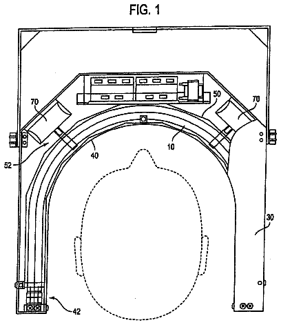
FIG. 1 is an external side configuration view of a corneal endothelial cell photographing apparatus in a first embodiment;
FIG. 2 is a schematic configuration view showing one example of optical arrangement of optical systems accommodated in a housing of a photographing part seen from above and a configuration of a control system;
FIG. 3 is a diagram of first and second projection optical systems seen from an examinee's side;
FIGS. 4A and 4B are diagrams showing one example of an anterior segment observation screen in photographing an endothelium of a corneal central portion, FIG. 4A showing a misaligned state and FIG. 4B showing a properly aligned state;
FIG. 5 is a flowchart showing main processing to be executed by a CPU;
FIG. 6 is a graph showing an epithelial peak detected on a detector;
FIG. 7 is a schematic diagram showing one example of an endothelium observation screen;
FIG. 8A is a first half of a flowchart showing observation and photographing processing to be executed in the main processing;
FIG. 8B is a second half of the flowchart showing the observation and photographing processing; and
FIG. 9 is a schematic diagram showing one example of a confirmation screen.
Detailed description of the exemplary embodiments
A typical embodiment of the present disclosure will be explained, referring to accompanying drawings. Referring to FIG. 1 , firstly, an external configuration of a corneal endothelial cell photographing apparatus 100 (hereinafter, simply referred to as a “photographing apparatus 100 ”) in the present embodiment will be explained. The following explanation is given on the assumption that an X direction in FIG. 1 is a right-and-left (lateral) direction, a Y direction is an up-and-down (vertical) direction, and a Z direction is a back-and-forth (longitudinal) direction.
The photographing apparatus 100 is an apparatus for photographing an image of a corneal portion of an examinee's eye E. The photographing apparatus 100 includes a photographing part 1 (a main unit), a table 2 , a head support unit 3 , and a movable unit 4 . This apparatus 100 is a so-called stationary apparatus. Optical systems in the photographing apparatus 100 are accommodated in a housing 1 a of the photographing part 1 .
The movable unit 4 is movable on the table 2 by a sliding mechanism not shown. In the movable unit 4 , an XYZ actuator (drive part) 5 is provided. The photographing part 1 is moved by the XYZ actuator 5 in the right-and-left direction (X direction), the up-and-down direction (Y direction), and the back-and-forth direction (Z direction) with respect to the eye E. The movable unit 4 is moved in the X-Z directions on the table 2 by operation of a joystick 6 . When a rotary knob 6 a is rotated by an examiner, the photographing part 1 is moved in the Y direction by Y-drive of the XYZ actuator 5 . At the top of the joystick 6 , a start switch 6 b is provided. A monitor 97 is placed on an examiner side of the housing 1 a of the photographing part 1 . In the present embodiment, the photographing part 1 is moved relative to the examinee's eye E by a sliding mechanism not shown or the XYZ actuator 5 .
The configuration of moving the photographing part 1 may be arranged to move the photographing part 1 by drive of a motor of the actuator 5 with respect to right and left eyes without providing any mechanical sliding mechanism. The apparatus 100 may also be provided with a touch panel or touchscreen serving as a manual operation member such as the joystick 6 .
In the present embodiment, the housing 1 a is provided with the monitor 97 on a surface opposite a side surface that will face to an examinee. However, this monitor 97 may be placed in another position of the housing 1 a or may be provided as a device separate from the photographing apparatus 100 .
Next, optical systems and a control system of the photographing apparatus 100 will be explained, referring to FIG. 2 . The optical arrangement shown in FIG. 2 is the layout of the optical systems accommodated in the photographing part 1 seen from above.
The photographing apparatus 100 mainly includes a cornea photographing optical system 10 and a Z alignment detecting optical system 85 . The photographing apparatus 100 in the present embodiment includes a front projection optical system 50 , first projection optical systems 60 a and 60 b , second projection optical systems 65 a to 65 d (see FIG. 3 ), a fixation optical system 70 ( 70 a to 70 i ), and an anterior segment observing optical system 80 .
The cornea photographing optical system 10 includes an illumination optical system 10 a and a light receiving optical system 10 b . The cornea photographing optical system 10 is configured to project the light from an illumination light source 11 (a first light source) to a cornea Ec of the examinee's eye E through the illumination optical system 10 a . The cornea photographing optical system 10 is also configured to receive, through an imaging device 22 , reflection light irradiated from the illumination light source 11 and reflected by the cornea Ec. The photographing apparatus 100 photographs a corneal portion of the eye E in a non-contact manner by use of the cornea photographing optical system 10 .
The optical axes of the illumination optical system 10 a and the light receiving optical system 10 b intersect each other, for example, on the examinee's eye E. It is advantageous to place those optical systems 10 a and 10 b symmetrically with respect to a certain center axis. In the present embodiment, an optical axis L 2 of the illumination optical system 10 a and an optical axis L 3 of the light receiving optical system 10 b are bilaterally symmetric with respect to the optical axis L 1 .
The illumination optical system 10 a in the present embodiment includes an illumination light source 11 , a condensing lens 12 , a slit plate 13 , a dichroic mirror 14 , and a light projecting lens 15 . The illumination light source 11 emits illumination light to be used in photographing a corneal portion. In the present embodiment, the illumination light source 11 emits visible light. As the illumination light source, for example, a visible LED, a flash lamp, and others may be employed. The dichroic mirror 14 reflects visible light, while transmits infrared light. The slit plate 13 and the cornea Ec are placed in almost conjugate positions with respect to the light projecting lens 15 . The light emitted from the illumination light source 11 is condensed by the condensing lens 12 and passes through a slit formed in the slit plate 13 . The slit light passing through the slit plate 13 is reflected by the dichroic mirror 14 and converged by the light projecting lens 15 and irradiated to the cornea Ec.
The light receiving optical system 10 b receives reflection light from the cornea Ec including endothelial cells through the imaging device 22 . This optical system 10 b in the present embodiment includes an objective lens 16 , a dichroic mirror 17 , a mask 18 , a first image-forming lens 19 , a total reflection mirror 20 , a second image-forming lens 21 , and a two-dimensional imaging device 22 (hereinafter, simply referred to as an “imaging device 22 ”). The dichroic mirror 17 reflects visible light, while transmits infrared light. The mask 18 is placed in an almost conjugate position with the cornea Ec. The first image-forming lens 19 and the second image-forming lens 21 constitute an image-forming optical system for forming an endothelial cell image on the imaging device 22 . The imaging device 22 is used to photograph endothelial cells. The imaging device 22 is placed in an almost conjugate position with the cornea Ec. As the imaging device 22 , for example, there may be employed a two-dimensional CCD image sensor (Charge Coupled Device image sensor), a two-dimensional CMOS (Complementary Metal Oxide Semiconductor image sensor), and others.
The light delivered from the illumination optical system 10 a to the cornea Ec is reflected by the cornea Ec toward an optical axis L 3 direction (an oblique direction). Thereafter, the light forms an image once on the mask 18 through the objective lens 16 and the dichroic mirror 17 . The mask 18 blocks the light that may become noise when an endothelial cell image is obtained. The light passing through the mask 18 forms an image on the imaging device 22 via the first image-forming lens 19 , the total reflection mirror 20 , and the second image-forming lens 21 . Thus, a highly magnified (zoomed-in) endothelial cell image is obtained.
The front projection optical system 50 projects an alignment target for alignment in X- and Y-directions (XY alignment) from front toward the cornea Ec. The front projection optical system 50 includes an infrared light source 51 , a light projecting lens 52 , and a half mirror 53 . When the infrared light source 51 lights up, the optical system 50 projects infrared light for XY alignment detection to the cornea Ec from the optical axis L 1 direction.
The first projection optical systems 60 a and 60 b and the second projection optical systems 65 a to 65 d project alignment targets for XYZ analysis. In the photographing apparatus 100 , rough alignment is performed by utilizing the alignment targets projected from the first projection optical system 60 a and 60 b and the second photographing optical system 65 a to 65 d.
The first projection optical systems 60 a and 60 b project infinite alignment targets toward the cornea Ec from oblique directions. The first projection optical systems 60 a and 60 b are arranged respectively at predetermined angles with respect to the optical axis L 1 . The first projection optical systems 60 a and 60 b respectively include infrared light sources 61 a and 61 b and collimator lenses 63 a and 63 b , and are arranged symmetric with respect to the optical axis L 1 and configured to project infinite targets to the eye E (see FIG. 3 ). The first projection optical systems 60 a and 60 b are located on approximately the same meridian as the horizontal direction passing the optical axis L 1 (see FIG. 3 ).
The lights emitted from the light sources 61 a and 61 b are collimated respectively by collimator lenses 63 a and 63 b , and then projected onto the cornea Ec, forming target images i 20 and i 30 (see FIG. 4 ).
The second projection optical systems 65 a to 65 d respectively project finite alignment targets toward the cornea Ec from a plurality of oblique directions. The second projection optical systems 65 a to 65 d are each placed at a slant with respect to the optical axis L 1 . The second projection optical systems 65 a to 65 d respectively include infrared light sources 66 a to 66 d and are arranged symmetric with respect to the optical axis L 1 to project the finite targets to the eye E. The second projection optical systems 65 a and 65 b are located above the optical axis L 1 and at the same level as each other in the Y direction. The second projection optical systems 65 c and 65 d are located below the optical axis L 1 and at the same level as each other in the Y direction. The second projection optical systems 65 a and 65 b and the second projection optical systems 65 c and 65 d are placed vertically symmetric with respect to the optical axis L 1 .
Herein, the lights from the light sources 66 a and 66 b are irradiated from upper oblique directions toward an upper part of the cornea Ec, forming target images i 40 and i 50 that are virtual images of the light sources 66 a and 66 b . Further, the lights from the light sources 66 c and 66 d are irradiated from lower oblique directions toward a lower part of the cornea Ec, forming target images i 60 and i 70 which are virtual images of the light sources 66 c and 66 d (see FIGS. 4A and 4B ).
According to the above-described target projection optical system, the target image i 10 is formed at a corneal apex of the eye E (see FIG. 4B ). The target images i 20 and i 30 by the first projection optical systems 60 a and 60 b are formed in the same horizontal positions as the target image i 10 and symmetric with respect to the target image i 10 . Further, the target images i 40 and i 50 by the second projection optical systems 65 a and 65 b are formed in positions above the target image i 10 and symmetric with respect to the target image i 10 . The target images i 60 and i 70 by the second projection optical systems 65 c and 65 d are formed in positions below the target image i 10 and symmetric with respect to the i 10 .
The photographing apparatus 100 includes a plurality of fixation optical systems (e.g., a fixation optical system 70 in FIG. 2 ). The fixation optical system 70 has a plurality of fixation lamps 71 (visible light sources (fixation light sources) 71 a to 71 i ) on a plane perpendicular to the optical axis, and lighting positions are changed over to change a visual line direction of an examinee's eye E.
The fixation optical system 70 ( 70 a to 70 i ) projects fixation targets from the inside of the housing 1 a to the eye E. Each of the fixation optical systems 70 a to 70 i includes one of visible light sources (fixation lamps) 71 a to 71 i , a light projecting lens 73 , and a dichroic mirror 74 . The visible light sources (fixation lamps) 71 a to 71 i are arranged at different positions in a direction perpendicular to the optical axis L 4 . The dichroic mirror 74 reflects visible light, while transmits infrared light. The visible lights emitted from the light sources 71 a to 71 i are converted into parallel light flux by the light projecting lens 73 , and then reflected by the dichroic mirror 74 . Thus, a fixation target is projected onto a fundus of the eye E. For example, the visible light source 71 a is arranged near the optical axis L 4 and used to guide the eye E to a front direction. The visible light sources 71 b to 71 i are lighted on when an endothelium image of a central portion of the cornea Ec is to be obtained. The plurality of visible light sources 71 b to 71 i are arranged on the circumference centered at the optical axis L 4 . FIG. 2 shows an example that the light sources 71 b to 71 i are arranged at angular intervals of 45°, that is, at each position of 0°, 45°, 90°, 135°, 180°, 225°, 270°, and 315°, when seen from an examinee's side. The visible light sources 71 b to 71 i are used to guide the direction of the visual line of the eye E to a circumferential direction to obtain an endothelium image around the corneal center portion. Moreover, an external fixation optical system may be further provided on the side surface of the housing 1 a on the examinee's side, even though the details and figure thereof are omitted. The present embodiment shows the case of using the optical system configured such that the plurality of fixation lamps placed at different positions are selectively lighted, thereby changing the direction to guide the visual line. The present disclosure is however not limited thereto. As an alternative, the present disclosure may include a configuration of moving a single fixation lamp in a direction perpendicular to the optical axis and changing the direction to guide the visual line of the examinee's eye E. As another alternative, a fixation optical system may include a display panel such as a liquid crystal display and an organic EL (electroluminescence) and control an emission position to change the direction to guide the visual line of the examinee's eye E.
The anterior segment observing optical system 80 is used for observation and photographing of an anterior segment image from front. This optical system 80 includes an objective lens 81 and a two-dimensional imaging device 82 (hereinafter, simply referred to as an “imaging device 82 ”). The imaging device 82 photographs an anterior segment image and an alignment target. Alignment in the X- and Y-directions and rough alignment in the Z direction are performed based on the alignment target images photographed by the imaging device 82 . As the imaging device 82 , for example, a two-dimensional CCD image sensor, a two-dimensional CMOS, and others may be employed. As the light source to be used for photographing the anterior segment, an anterior segment illumination light source not shown is used.
In the present embodiment, the Z alignment detecting optical system 85 is utilized for accurate alignment in the Z direction. This Z alignment detecting optical system 85 includes a light projecting optical system 85 a and a detecting optical system 85 b . In the present embodiment, the optical axis L 2 of the light projecting optical system 85 a and the optical axis L 3 of the detecting optical system 85 b are arranged in bilaterally symmetric positions with respect to the optical axis L 1 . The Z alignment detecting optical system 85 is configured to project the light (i.e., detection light) in a first oblique direction to the cornea Ec to detect a focus state of the cornea photographing optical system 10 with respect to the cornea Ec of the eye E. On the other hand, the detecting optical system 85 b is provided with a detector 89 in which a plurality of pixels are arranged. The detector 89 receives reflection light projected from the light projecting optical system 85 a and reflected by the cornea Ec. The detecting optical system 85 b receives, in a second oblique direction opposite to the first oblique direction, corneal reflection light resulting from the detection light projected from the light projecting optical system 85 a and including reflection light from the corneal endothelium, and thus detects an intensity distribution of the corneal reflection light in a depth direction.
The light projecting optical system 85 a in the present embodiment includes an illumination light source 86 , a condensing lens 87 , a pinhole plate 88 , and the lens 15 . The pinhole plate 88 is placed in an almost conjugate position with the cornea Ec. The detecting optical system 85 b in the present embodiment includes the lens 16 and the detector 89 . As the detector 89 , for example, a one-dimensional light receiving element (a line sensor) may be used. The detector 89 and the cornea Ec are located in almost conjugate positions. Infrared light emitted from the light source 86 illuminates the pinhole plate 88 via the condensing lens 87 . The light passing through an aperture of the pinhole plate 88 is projected onto the cornea Ec via the lens 15 . The light is then reflected by the cornea Ec toward the optical axis L 3 . Thereafter, the corneal reflection light is received by the detector 89 via the lens 16 and the dichroic mirror 17 . The detector 89 outputs a signal representing the intensity distribution of corneal reflection light in the depth direction to a controller 90 .
The signal output from the detector 89 is utilized to detect the alignment state in the Z direction. Herein, the received position of the detection light on the detector 89 changes according to the positional relationship between the photographing part 1 and the examinee's eye E in the Z direction. The photographing apparatus 100 detects misalignment between the light received position of the detection light and an alignment proper position to detect an amount of misalignment in the Z direction.
A schematic configuration of the control system of the photographing apparatus 100 will be explained below.
In the photographing apparatus 100 , the controller 90 controls each part of the apparatus 100 . The controller 90 is connected to the actuator 5 , the joystick 6 , various light sources 11 , 71 , 51 , 61 , and 86 , the imaging devices 22 and 82 , the detector 89 , the HDD 94 , the image processing IC 95 , an operation input unit (a user interface) 96 , and the monitor 97 . The monitor 97 may employ a touch panel. In this case, the monitor 97 also serves as a part of the operation input unit 96 .
The controller 90 includes a CPU 91 , a ROM 92 , and a RAM 93 . The CPU 91 is a processing unit for executing various processings in the photographing apparatus 100 . The ROM 92 is a nonvolatile storage unit that stores various control programs and fixed data. The RAM 93 is used as a rewritable volatile storage unit, but is not limited thereto. The RAM 93 stores temporary data when the control program is to be executed.
The HDD 94 is used as a rewritable nonvolatile storage unit, but is not limited thereto. In the present embodiment, the HDD 94 stores a program of a main processing which will be described later. An image of the examinee's eye E photographed by the photographing apparatus 100 is stored in the HDD 94 .
The image processing IC 95 is used as an image processing section. The image processing IC 95 processes a signal output from the imaging device 22 to create an endothelial cell image (hereinafter, referred to as an “endothelial image”). Further, the image processing IC 95 processes a signal output from the imaging device 82 to create an anterior segment front image (hereinafter, referred to as an “anterior segment image”). For instance, when the endothelial cell image is to be observed, the image processing IC 95 sequentially creates the endothelial images and the anterior segment images. Each of the crated images is successively output to the monitor 97 . Thus, on an observation-photographing screen (an endothelium observation screen) 300 of the monitor 97 (see FIG. 7 ), the anterior segment front image and the corneal endothelial image are displayed as an observation image (a live image). When the endothelial image is to be photographed (captured), the CPU 91 makes the HDD 94 to store the endothelial image created by the image processing IC 95 .
Operations of the photographing apparatus 100 will be explained below, referring to FIG. 5 . The main processing shown in FIG. 5 is executed when the power of the photographing apparatus 100 is turned on. In the main processing, firstly, the alignment of the apparatus 100 with respect to the examinee's eye E is performed by use of the anterior segment image obtained through the anterior segment observing optical system 80 (S 1 to S 6 ). The fixation lamp 71 is turned on (S 1 ). Herein, the fixation lamp 71 a near the optical axis L 4 is lighted. Further, the CPU 91 starts lighting of an anterior segment observation light source not shown and starts creation of an anterior segment image (a live image) by the image processing IC 95 and output of the image to the monitor 97 (S 2 ). Further, the CPU 91 causes the monitor 97 to display the anterior segment observation screen 200 (see FIG. 4 ) (S 3 ). The anterior segment observation screen 200 is displayed when the position of the photographing part (measuring part) 1 is to be aligned with the examinee's eye E. On the anterior segment observation screen 200 , an anterior segment image photographed in real time is displayed. While checking or confirming this screen 200 , an examiner operates the joystick 6 to adjust the position of the photographing part 1 with respect to the examinee's eye E.
Subsequently, the light source for alignment is turned on (S 3 ). Further, the alignment processing is executed (S 4 ). In this alignment processing (S 4 ), alignment of the photographing part 1 with respect to the eye E is performed. In the present embodiment, the alignment in the X- and Y-directions is carried out in two stages; rough alignment performed manually by operation of the joystick 6 and automatic alignment. While the manual alignment is being performed by operation of the joystick 6 , the CPU 91 detects the target images i 40 , i 50 , i 60 , and i 70 of the targets projected by the second projection optical systems 65 a to 65 d . As soon as the target images i 40 to i 70 get detected, the CPU 91 detects the center position of a rectangle formed by the target images i 40 to i 70 as a nearly corneal apex and detects a misalignment direction and/or deviation amount in the X- and Y-directions. The CPU 91 moves the photographing part 1 in the X- and Y-directions to bring the misalignment into an allowable range. When a target image i 10 is detected, accordingly, the CPU 91 terminates the alignment using the target images i 40 to i 70 and starts alignment using the target image i 10 . The CPU 91 moves the photographing part 1 in the X- and Y-directions to bring the displacement amount between the target image i 10 and an alignment reference point (e.g., the center of the screen 20 a ) into an allowable range. The alignment in the X- and Y-directions is performed in the above manner.
In the present embodiment, the alignment in the Z direction is carried out in two stages; first automatic alignment and second automatic alignment. The first automatic alignment uses a detection result of the infinite target images i 20 and i 30 and the finite target images i 60 and i 70 . When the target image i 10 gets detected, the infinite target images i 20 and i 30 are also detected. The CPU 91 compares an interval between the target images i 20 and i 30 and an interval between the target images i 60 and i 70 to determine a misalignment direction and/or deviation amount in the Z direction (first alignment detection). Further, the CPU 91 moves the photographing part 1 in the Z direction to bring the Z-direction misalignment into an allowable range (first automatic alignment). Herein, the Z-direction misalignment is determined by utilizing the characteristic that the interval between the infinite target images i 20 and i 30 changes little when the photographing part 1 is displaced in an operating direction, whereas the interval between the finite target images i 60 and i 70 changes (for the details, see JP-A-H6(1994)-46999). It is to be noted that the target images i 40 and i 50 may be used instead of the target images i 60 and i 70 . An alignment state in the Z direction may be detected based on a distance of a target (target height) from the optical axis L 1 .
After completion of the first automatic alignment, the second automatic alignment is performed. This second automatic alignment uses the Z alignment detecting optical system 85 ( 85 a and 85 b ). During the second automatic alignment, the CPU 91 lights the light source 86 to continuously project detection light from the light projecting optical system 85 a to the cornea Ec. The light source 86 may be lighted up in advance. This continuous light projection may be always-on light projection or intermittent light projection. The light projection control of detection light is not limited to lighting control of the light source 86 . For instance, a light-blocking drive part (e.g., AOM) may be provided in the light projecting optical system 85 a . In this case, the CPU 91 controls the light-blocking part to control projection of the detection light.
Corneal reflection light of the detection light is detected by the detector 89 of the detecting optical system 85 b . The CPU 91 controls the actuator 5 based on a signal output from the detector 89 to thereby move the photographing part 1 in the Z direction. For instance, the CPU 91 detects a peak P corresponding to the reflection light from the corneal epithelium in a waveform indicating an intensity distribution of the corneal reflection light in the depth direction, based on the intensity distribution represented by the signal output from the detector 89 (see FIG. 6 ). The actuator 5 is driven so that a position Pz of the epithelium peak on the detector 89 comes to the position of a predetermined pixel (e.g., the position of a center pixel). In the photographing apparatus 100 , accordingly, focus of the cornea photographing optical system 10 is set on or near the corneal epithelium. When the alignment state in the X-, Y-, and Z-directions satisfies an alignment completion condition, the CPU 91 terminates the alignment processing (S 4 ) and turns off the alignment light source (S 5 ).
The CPU 91 may detect the peak corresponding to reflection light beam from a corneal endothelium in a waveform representing the intensity of the reflection light beam from the cornea Ec per depth of the cornea Ec, based on the intensity distribution output from the detector 89 (see FIG. 6 ). The actuator 5 may also be driven to bring the position of the endothelial peak on the detector 89 to a predetermined pixel (e.g., the position of a center pixel) on the detector 89 . In the photographing apparatus 100 , accordingly, focus of the cornea photographing optical system 10 is set on or near the corneal endothelium.
The CPU 91 then executes the observation and photographing processing (S 6 ). In this observation and photographing processing (S 6 ), displaying an observation image of the corneal endothelium (a live image of endothelial image in the present embodiment) and acquiring and storing (capturing) of the photographed image are performed. When the observation and photographing processing (S 6 ) is carried out, the endothelium observation screen 300 is displayed on the monitor 97 (see FIG. 7 ). The live image of endothelial image is displayed in an endothelium window 301 on the endothelium observation screen 300 . The endothelium observation screen 300 displays thereon corneal reflection light information together with the endothelial image. The corneal reflection light information relates to the intensity of corneal reflection light received by the detector 89 per corneal depth (i.e., an intensity distribution of corneal reflection light in the depth direction (Z direction), including at least an intensity distribution corresponding to the reflection light from the corneal endothelium). Subsequent to the second automatic alignment, the CPU 91 controls the light projecting optical system 85 a to continuously project the detection light.
In the present embodiment, the intensity distribution of corneal reflection light in the depth direction is shown as a waveform in a waveform graph 302 . In a case of displaying the intensity distribution as a waveform, a raw signal may be displayed or a processed signal (e.g., a signal generated by smoothing processing, amplitude emphasizing processing, etc.) may be displayed. Since the detection light is strongly reflected by the epithelium and the endothelium of the cornea Ec, as shown in FIG. 7 , the information indicating that strong reflection is obtained at two locations is obtained as the corneal reflection light information. In this case, for example, the waveform graph 302 shows a waveform having two peaks, that is, a peak indicating reflection from the epithelium (i.e., epithelium peak) and a peak indicating reflection from the endothelium (i.e., endothelial peak) (see FIG. 7 ). However, the corneal reflection light is condensed most preferably at a predetermined pixel of the detector 89 (a center pixel in the present embodiment) and the corneal reflection light is difficult to be condensed at a pixel located in a position more away from the predetermined pixel. Thus, as compared with a case where the reflection light from the endothelium enters the predetermined pixel or another pixel located near it, as the reflection light from the endothelium enters in a pixel located more away from the predetermined pixel, a detection signal of the reflection light from the endothelium is lower in intensity. Accordingly, when the reflection light from the endothelium enters the pixel located greatly away from the predetermined pixel, an endothelial peak may be not formed. Regarding the waveform graph 302 in FIG. 7 , a left side in the drawing sheet corresponds to an apparatus side and a right side corresponds to a fundus side.
When the focus position is displaced, the waveform in the waveform graph 302 is shifted in a right-and-left direction on the screen. In FIG. 7 , when the focus position is moved to the fundus side, the waveform shifts to the left on the drawing sheet of FIG. 7 , while when the focus position is moved to the corneal epithelium side, the waveform is shifted to the right on the drawing sheet of FIG. 7 . In the present embodiment, the focus position of the cornea photographing optical system 10 on the waveform graph 302 is set at the center of the waveform graph 302 in the right-and-left direction (that is, the center position of the endothelium window 301 in the right-and-left direction in FIG. 7 ). In the present embodiment, therefore, an examiner can recognize the focus position with reference to the position of the waveform peak with respect to the center position of the waveform graph 302 in the right-and-left direction. In FIG. 7 , the corneal reflection light information (waveform graph 302 ) is displayed to be superimposed on the endothelial image. However, the corneal reflection light information has only to be displayed simultaneously with the endothelial image and is not limited to the display example in the present embodiment.
In the present embodiment, an anterior segment window 303 is placed in the endothelium observation screen 300 . The CPU 91 causes the anterior segment window 303 to display thereon a live image of the anterior segment image generated in the image processing IC 95 . The corneal reflection light information (e.g., a waveform graph 303 a ) may be displayed in the anterior segment window.
On the endothelium observation screen 300 , a fixation position graphic 304 is displayed. This fixation position graphic 304 represents the positions of the lighted fixation lamps 71 seen from the examinee's eye E. The fixation position graphic 304 enables the examiner to easily recognize the photographing position of the endothelial image around the corneal center.
Herein, referring to flowcharts in FIGS. 8A and 8B , one example of the observation and photographing processing (S 6 ) will be explained more concretely. In the observation and photographing processing (S 6 ), firstly, a photographing mode in the controller 90 is set to an automatic photographing mode (S 11 ).
<Automatic Photographing Mode>
When the automatic photographing mode is established, the CPU 91 controls driving of the actuator 5 based on the intensity distribution (or a signal) output from the detector 89 to automatically adjust the focus position of the cornea photographing optical system 10 to the corneal epithelium or endothelium. In the automatic photographing mode in the present embodiment, photographing and storing of the endothelial image are also automatically performed. In the present embodiment, as the photographing mode in the controller 90 , a manual photographing mode may be set as well as the automatic photographing mode. In the manual photographing mode, the details of which will be mentioned later, the focus position of the cornea photographing optical system 10 is adjusted according to a command from the examiner.
After setting the automatic photographing mode, the CPU 91 gives the image processing IC 95 a command to start creating the endothelial image and displaying this image on the monitor 97 (S 12 ). As a result of this command, a live image of the endothelial image is displayed in the endothelium window 301 .
The CPU 91 then acquires a signal from the detector 89 (S 13 ). When this signal is processed, a waveform representing an intensity distribution of corneal reflection light in the depth direction (that is, the Z direction and the back-and-forth direction) is obtained (S 14 ). The waveform obtained by the processing in S 14 is displayed as the waveform graph 302 on the monitor 97 (S 15 ).
Further, the CPU 91 makes a determination processing on an alignment signal output from the detector 89 to obtain the focus position information representing the focus position of the cornea photographing optical system 10 (S 17 ). In the present embodiment, the focus position information with respect to the epithelium is obtained. The focus position information with respect to the epithelium can be obtained as a value corresponding (proportional) to a difference between the epithelium peak position in the waveform graph 302 and the focus position (that is, the center of the waveform graph 302 in the right-and-left direction). Needless to say, focus position information with respect to endothelium may be obtained as well as the focus position information with respect to epithelium.
The CPU 91 subsequently displays the focus position information obtained by the processing in S 16 on the monitor 97 (S 17 ). The focus position information may be indicated by graphic or numerical value. For instance, in the present embodiment, the distance from the corneal epithelium to a real focus position is indicated by numerical value in a text box 307 .
The description continues in the full USPTO document.
 Lapsed, fee not paid5 drawings