 Lapsed, fee not paid7 drawings
Industrial Equipment · US 8,798,432 B2
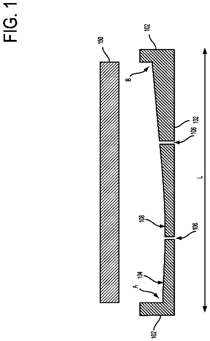
Fabrication of a laminated optical wedge
Embodiments are disclosed that relate to fabrication of a laminated optical wedge.
US 8,798,877 B2 · Assignee: Toyota Jidosha Kabushiki Kaisha · Inventors: Ayabe; Atsushi et al.
Sheet 1 of 9 from the published document. All sheets in the USPTO PDF
A control device of a continuously variable transmission for a vehicle has a pair of variable pulleys and a transmission belt, and the control device respectively controls input-side and output-side thrust forces of input-side and output-side variable pulleys to set an actual gear ratio to a target gear ratio, prevents a slip of the transmission belt, and determines a lowest-speed-side gear ratio. When it is determined that a detection value of a rotation speed for calculating the actual gear ratio does not reflect an actual rotation speed, target input-side and output-side thrust forces are set to be target thrust forces for maintaining the lowest-speed-side gear ratio and preventing the slip of the transmission belt, and based on whether the actual gear ratio is already the lowest-speed-side gear ratio, values of the input-side and output-side thrust forces are changed for obtaining the target thrust forces.
A control device of a continuously variable transmission for a vehicle (hereinafter, continuously variable transmission) is well known that has a pair of variable pulleys with variable effective diameters of an input-side variable pulley (a primary pulley, a primary sheave) and an output-side variable pulley (a secondary pulley, a secondary sheave) and a transmission belt wrapped around between the pair of the variable pulleys and that respectively controls an input-side thrust force (a primary thrust force) in the primary sheave and an output-side thrust force (secondary thrust force) in the secondary sheave to set an actual gear ratio to a target gear ratio and preventing a slip of the transmission belt. This corresponds to control devices for vehicles described in Patent Documents 1 and 2. Generally, in such a continuously variable transmission, for example, the primary thrust force a
1 of 9 drawing sheets so far from the published document, cropped to the drawing. Every sheet is in the USPTO PDF.
What the patent claimed, word for word. All of it is now free to use.
The present invention relates to a control device of a continuously variable transmission for a vehicle that is a belt type continuously variable transmission respectively controlling an input-side thrust force and an output-side thrust force to achieve a gear ratio and having a lowest-speed-side gear ratio mechanically determined.
A control device of a continuously variable transmission for a vehicle (hereinafter, continuously variable transmission) is well known that has a pair of variable pulleys with variable effective diameters of an input-side variable pulley (a primary pulley, a primary sheave) and an output-side variable pulley (a secondary pulley, a secondary sheave) and a transmission belt wrapped around between the pair of the variable pulleys and that respectively controls an input-side thrust force (a primary thrust force) in the primary sheave and an output-side thrust force (secondary thrust force) in the secondary sheave to set an actual gear ratio to a target gear ratio and preventing a slip of the transmission belt. This corresponds to control devices for vehicles described in Patent Documents 1 and 2. Generally, in such a continuously variable transmission, for example, the primary thrust force and the secondary thrust force are set to control a pulley pressure (primary pressure) in the input-side variable pulley and a pulley pressure (secondary pressure) in the output-side variable pulley such that a target gear ratio is achieved while preventing a belt slip, and feedback control is provided based on a deviation between an actual gear ratio calculated by using detection values of an input-side rotation speed and an output-side rotation speed in the continuously variable transmission (actual gear ratio=input-side rotation speed/output-side rotation speed) and a target gear ratio to fine-tune and control the primary pressure (or primary thrust force), for example.
To accurately calculate the actual gear ratio, the input-side rotation speed and the output-side rotation speed must more accurately be detected by a rotation sensor, for example. However, because of the characteristics of the rotation sensor, for example, a rotation speed may not accurately be detected in an extremely low rotation speed range and a detection value of a rotation speed may not reflect an actual rotation speed (actual rotation speed). If such a rotation sensor is used, the target gear ratio can properly be achieved in the running state in which a detection value of a rotation speed reflects the actual rotation speed. However, in the running state in which a detection value of a rotation speed does not reflect the actual rotation speed, the actual gear ratio is not known and the target gear ratio may not properly be achieved because of control variations etc. in a thrust force (or pulley pressure) and an input torque assumed in this case. Particularly, to ensure the vehicle restart during vehicle stop or the reacceleration performance during low-speed running, it is desired to maintain a gear ratio of the continuously variable transmission at a lowest-speed-side gear ratio (a Lowest, a maximum gear ratio). Therefore, during vehicle decelerated running while a gear ratio is controlled toward the lowest-speed-side gear ratio, it is desirable to control the gear ratio to the lowest-speed-side gear ratio during the running state in which a detection value of a rotation speed from the rotation sensor reflects the actual rotation speed.
However, for example, during rapid deceleration running, the gear ratio may not be returned to the lowest-speed-side gear ratio during the running state in which a detection value of a rotation speed reflects the actual rotation speed and it may become unknown whether the gear ratio is finally set to the lowest-speed-side gear ratio. For such a problem, for example, Patent Document1 proposes to fix the pulley pressures (primary pressure and secondary pressure) and limit the input torque at the restart of a vehicle in accordance with the determination of possibility of an improper speed change preventing a gear ratio from returning to the lowest-speed-side gear ratio when a vehicle is stopped, and to cancel the fixation and limitation when a rotation sensor can properly detect a rotation speed.
Patent Documents
Patent Document 1: Japanese Laid-Open Patent Publication No. 2006-342837
Patent Document 2: Japanese Laid-Open Patent Publication No. 2007-255625
Problems to Be Solved by the Invention
However, the technique proposed by Patent Document 1 does not assure a belt return, i.e., a return of the gear ratio to the lowest-speed-side gear ratio. Since input torque is limited, i.e., the torque is lowered at the restart of a vehicle, the acceleration performance (start performance) at the restart is not certainly ensured. On the other hand, with regard to the problem, separately from Patent Document 1, it is conceivable to maintain the lowest-speed-side gear ratio by keeping the primary thrust force and the secondary thrust force high so as to provide control such that no belt slip occurs. However, in this case, although the lowest-speed-side gear ratio can be achieved, because the primary thrust force and the secondary thrust force are made higher than necessary, the pulley pressures are always made higher during low-speed running and during vehicle stop and, therefore, fuel efficiency may be reduced. The problems described above are not well-known and no proposal has hitherto been made on retaining the gear ratio to the lowest-speed-side gear ratio without causing a belt slip regardless of whether a gear ratio is returned to the lowest-speed-side gear ratio during the running state in which a detection value of a rotation speed reflects the actual rotation speed.
The present invention was conceived in view of the situations and it is therefore an object of the present invention to provide a control device of a continuously variable transmission for a vehicle capable of retaining a gear ratio to a lowest-speed-side gear ratio without causing a belt slip even when a detection value of a rotation speed does not reflect an actual rotation speed.
Means for Solving the Problems
To achieve the object, the present invention provides (a) a control device of a continuously variable transmission for a vehicle having a pair of variable pulleys with variable effective diameters of an input-side variable pulley and an output-side variable pulley and a transmission belt wrapped around between the pair of the variable pulleys, the continuously variable transmission respectively controlling an input-side thrust force of the input-side variable pulley and an output-side thrust force of the output-side variable pulley to set an actual gear ratio to a target gear ratio and preventing a slip of the transmission belt, the continuously variable transmission having a lowest-speed-side gear ratio determined by mechanically preventing movement of an input-side rotating body moved in an axial direction for varying an effective diameter of the input-side variable pulley, (b) the control device differentiating control methods of the input-side thrust force and the output-side thrust force based on whether the actual gear ratio is already the lowest-speed-side gear ratio if it is determined that a detection value of a rotation speed for calculating the actual gear ratio does not reflect an actual rotation speed.
Consequently, if it is determined that an actual rotation speed is not reflected by a detection value of a rotation speed for calculating the actual gear ratio, the control methods of the input-side thrust force and the output-side thrust force are differentiated based on whether the actual gear ratio is already the lowest-speed-side gear ratio and, therefore, for example, even when the actual rotation speed is not reflected by the detection value of the rotation speed, the actual gear ratio can be retained at the lowest-speed-side gear ratio without causing a belt slip of the continuously variable transmission for a vehicle regardless of whether the actual gear ratio is already the lowest-speed-side gear ratio.
Preferably, if the actual gear ratio is already the lowest-speed-side gear ratio, a target input-side thrust force and a target output-side thrust force are set to be thrust forces for maintaining the lowest-speed-side gear ratio and preventing a slip of the transmission belt, and wherein the target input-side thrust force is made lower by a predetermined value. Consequently, for example, the control can be provided such that a slip of the transmission belt is prevented from occurring while maintaining the lowest-speed-side gear ratio. Since the input-side pulley pressure in the input-side variable pulley can be reduced, the fuel efficiency improving effect can be acquired. In other words, if it is known that the actual gear ratio is the lowest-speed-side gear ratio, the input-side movable rotating body is mechanically prevented from moving (is abutting on a hardware limit) and the reduction of the input-side pulley pressure from the pulley pressure for maintaining the lowest-speed-side gear ratio does not move the input-side movable rotating body and does not reduce the belt clamping pressure any more. Therefore, even if the target input-side thrust force is made lower by a predetermined value, the lowest-speed-side gear ratio can be maintained while a slip of the transmission belt is prevented.
Preferably, if the actual gear ratio is not yet the lowest-speed-side gear ratio, a target input-side thrust force and a target output-side thrust force are set to be thrust forces for maintaining the lowest-speed-side gear ratio and preventing a slip of the transmission belt, and wherein the target output-side thrust force is made higher by a predetermined value. Consequently, for example, even if the gear ratio does not reach the lowest-speed-side gear ratio during the running state in which the detection value of the rotation speed reflects the actual rotation speed, a belt slip can be prevented while the gear ratio is controlled toward the lowest-speed-side gear ratio. In other words, if the lowest-speed-side gear ratio is not reached, the movement position of the input-side movable rotating body is unknown and, therefore, when the input-side pulley pressure is reduced from the pulley pressure for maintaining the lowest-speed-side gear ratio, the input-side movable rotating body may move in the direction of loosening the transmission belt and cause a belt slip. Therefore, only the target output-side thrust force is made higher by a predetermined value relative to the thrust forces for maintaining the lowest-speed-side gear ratio to maintain the lowest-speed-side gear ratio and preventing a slip of the transmission belt.
Preferably, the thrust forces for maintaining the lowest-speed-side gear ratio are sequentially set based on an input torque of the continuously variable transmission for a vehicle, and wherein the predetermined value is a value obtained in advance to correspond control variation amounts of the input-side thrust force and the output-side thrust force for certainly acquiring the thrust forces capable of maintaining the lowest-speed-side gear ratio when the thrust forces are controlled. Consequently, the lowest-speed-side gear ratio can properly be maintained while a slip of the transmission belt is certainly prevented, for example.
Preferably, the control methods of the input-side thrust force and the output-side thrust force are differentiated during vehicle deceleration running when the gear ratio is controlled toward the lowest-speed-side gear ratio. Consequently, the actual gear ratio can be retained at the lowest-speed-side gear ratio without causing a belt slip of the continuously variable transmission for a vehicle during vehicle stop and during extremely-low-speed running, for example. Therefore, the vehicle restart performance during vehicle stop and the reacceleration performance during low-speed running are properly ensured.
Preferably, a detection value of the rotation speed is within a rotation speed range less than an extremely low rotation speed obtained in advance as a rotation speed range in which the reliability of the detection value is reduced, it is determined that the detection value of the rotation speed does not reflect an actual rotation speed. Consequently, the actual gear ratio can be retained at the lowest-speed-side gear ratio without causing a belt slip of the continuously variable transmission for a vehicle during vehicle stop and during extremely-low-speed running, for example. Therefore, the vehicle restart performance during vehicle stop and the reacceleration performance during low-speed running are properly ensured.
FIG. 1 is a diagram for explaining a general configuration of a power transmission path making up a vehicle to which the present invention is applied.
FIG. 2 is a block diagram for explaining a main portion of a control system disposed in the vehicle.
FIG. 3 is a hydraulic circuit diagram of a main portion relevant to hydraulic control related to the shift of the continuously variable transmission in the hydraulic control circuit.
FIG. 4 is a functional block diagram for explaining a main portion of the control function of the electronic control device.
FIG. 5 is a diagram of an example of a shift map used when a target input shaft rotation speed is obtained in the hydraulic control related to the shift of the continuously variable transmission.
FIG. 6 is a diagram of an example of a thrust force map to obtain a target secondary thrust force depending on gear ratios etc., in the hydraulic control related to the shift of the continuously variable transmission.
FIG. 7 is a diagram of an example of a map between the engine rotation speed and the engine torque empirically obtained and stored in advance by using the intake air quantity as a parameter.
FIG. 8 is a diagram of an example of a map empirically obtained and stored in advance as a predetermined operation characteristic of the torque converter.
FIG. 9 is a diagram of an example of a relationship between a target gear ratio and a thrust force ratio set in advance for determining the thrust force ratios of the variable pulleys based on the target gear ratio in the hydraulic control related to the shift of the continuously variable transmission.
FIG. 10 is a flowchart for explaining a main portion of the control operation of the electronic control device, i.e., the control operation for achieving the maximum gear ratio without causing a belt slip even when the rotation sensor detection value does not reflect the actual rotation speed.
FIG. 11 is a time chart of an example when the control operation depicted in the flowchart of FIG. 10 is performed.
FIG. 12 is a time chart of an example when the control operation depicted in the flowchart of FIG. 10 is performed, and is a different embodiment from FIG. 11.
In the present invention, preferably, the input-side thrust force and the output-side thrust force are respectively directly or indirectly controlled by configuring a control circuit such that the pulley pressures acting on the input-side variable pulley and the output-side variable pulley are controlled independently of each other.
An embodiment of the present invention will now be described in detail with reference to the drawings.
Embodiment
FIG. 1 is a diagram for explaining a general configuration of a power transmission path from an engine 12 to drive wheels 24 making up a vehicle 10 to which the present invention is applied. In FIG. 1, for example, the power generated by the engine 12 used as a drive force source for running is transmitted sequentially through a torque converter 14 acting as a hydraulic transmission device, a forward/reverse switching device 16, a belt type continuously variable transmission 18 (hereinafter referred to as a continuously variable transmission (CVT)) acting as a continuously variable transmission for a vehicle, a reduction gear device 20, a differential gear device 22, etc., to the left and right drive wheels 24.
The torque converter 14 includes a pump impeller 14p coupled to a crankshaft 13 of the engine 12 and a turbine impeller 14t coupled to the forward/reverse switching device 16 via a turbine shaft 30 corresponding to an output-side member of the torque converter 14 to transmit power via fluid. A lockup clutch 26 is disposed between the pump impeller 14p and the turbine impeller 14t, and the complete engagement of the lockup clutch 26 causes the pump impeller 14p and the turbine impeller 14t to integrally rotate. The pump impeller 14p is coupled to a mechanical oil pump 28 rotationally driven by the engine 12 to generate an operating oil pressure for providing shift control to the continuously variable transmission 18, to generate a belt clamping pressure in the continuously variable transmission 18, to control a torque capacity of the lockup clutch 26, to switch a power transmission path in the forward/reverse switching device 16, and to supply lubricant oil to the portions of the power transmission path of the vehicle 10.
The forward/reverse switching device 16 is mainly made up of a forward clutch C1, a reverse brake B1, and a double pinion type planetary gear device 16p with a sun gear 16s integrally coupled to the turbine shaft 30 of the torque converter 14 and a carrier 16c integrally coupled to an input shaft 32 of the continuously variable transmission 18 and, on the other hand, the carrier 16c and the sun gear 16s are selectively coupled via the forward clutch C1 while a ring gear 16r is selectively fixed via the reverse brake B1 to a housing 34 acting as a non-rotating member. The forward clutch C1 and the reverse brake B1 correspond to an interrupting device and both are hydraulic friction engagement devices caused to be frictionally engaged by a hydraulic cylinder.
In the forward/reverse switching device 16 configured as above, when the forward clutch C1 is engaged and the reverse brake B1 is released, the forward/reverse switching device 16 is put into an integrally rotating state and the turbine shaft 30 is directly coupled to the input shaft 32 to establish (achieve) a forward power transmission path, thereby transmitting a drive force in the forward direction to the continuously variable transmission 18. When the reverse brake B1 is engaged and the forward clutch C1 is released, a reverse power transmission path is established (achieved) in the forward/reverse switching device 16 and the input shaft 32 is rotated in the reverse direction relative to the turbine shaft 30, thereby transmitting a drive force in the reverse direction to the continuously variable transmission 18. When both the forward clutch C1 and the reverse brake B1 are released, the forward/reverse switching device 16 is put into a neutral state (power transmission interrupted state) in which the power transmission is interrupted.
The engine 12 is made up of an internal-combustion engine such as a gasoline engine and a diesel engine, for example. An intake pipe 36 of the engine 12 is disposed with an electronic throttle valve 40 for electrically controlling an intake air quantity Q.sub.AIR of the engine 12 by using a throttle actuator 38.
The continuously variable transmission 18 includes a pair of variable pulleys 42 and 46 that are the input-side variable pulley (the primary pulley, the primary sheave) 42 having a variable effective diameter, i.e., an input-side member disposed on the input shaft 32, and the output-side variable pulley (the secondary pulley, the secondary sheave) 46 having a variable effective diameter, i.e., an output-side member disposed on an output shaft 44, and a transmission belt 48 wrapped around between the pair of the variable pulleys 42 and 46, and the power is transmitted through a frictional force between the pair of the variable pulleys 42, 46 and the transmission belt 48.
The input-side variable pulley 42 includes a fixed rotating body 42a as an input-side fixed rotating body fixed to the input shaft 32, a movable rotating body 42b as an input-side movable rotating body disposed relatively non-rotatably around the axis and movably in the axial direction relative to the input shaft 32, and an input-side hydraulic cylinder (primary-side hydraulic cylinder) 42c as a hydraulic actuator applying an input-side thrust force (primary thrust force) Win (=a primary pressure Pin.times.a pressure receiving area) in the input-side variable pulley 42 for changing a V-groove width therebetween. The output-side variable pulley 46 includes a fixed rotating body 46a as an output-side fixed rotating body fixed to the output shaft 44, a movable rotating body 46b as an output-side movable rotating body disposed relatively non-rotatably around the axis and movably in the axial direction relative to the output shaft 44, and an output-side hydraulic cylinder (secondary-side hydraulic cylinder) 46c as a hydraulic actuator applying an output-side thrust force (secondary thrust force) Wout (=a secondary pressure Pout.times.a pressure receiving area) in the output-side variable pulley 46 for changing a V-groove width therebetween.
The primary pressure Pin, i.e., an oil pressure to the input-side hydraulic cylinder 42c, and the secondary pressure Pout, i.e., an oil pressure to the output-side hydraulic cylinder 46c, are adjusted and controlled independently of each other by a hydraulic control circuit 100 (see FIG. 3) to respectively directly or indirectly control the primary thrust force Win and the secondary thrust force Wout. As a result, the V-groove widths of the pair of the variable pulleys 42 and 46 are changed to vary the wrapping diameters (effective diameters) of the transmission belt 48 so as to continuously vary a gear ratio (gear ratio) .gamma. (=input shaft rotation speed N.sub.IN/output shaft rotation speed N.sub.OUT) while a friction force (belt clamping pressure) between the pair of the variable pulleys 42, 46 and the transmission belt 48 is controlled so as not to cause a slip of the transmission belt 48.
Therefore, the primary thrust force Win and the secondary thrust force Wout are respectively controlled to set an actual gear ratio (actual gear ratio) .gamma. to a target gear ratio .gamma.* while a slip of the transmission belt 48 is prevented. The input shaft rotation speed N.sub.IN is a rotation speed of the input shaft 32 and the output shaft rotation speed N.sub.OUT is a rotation speed of the output shaft 44. In the present embodiment, as can be seen from in FIG. 1, the input shaft rotation speed N.sub.IN is the same as the rotation speed of the input-side variable pulley 42 and the output shaft rotation speed N.sub.OUT is the same as the rotation speed of the output-side variable pulley 46.
In the continuously variable transmission 18, for example, when the primary pressure Pin is increased, the V-groove width of the input-side variable pulley 42 is narrowed and the gear ratio .gamma. is reduced, i.e., the continuously variable transmission 18 is shifted up. When the primary pressure Pin is decreased, the V-groove width of the input-side variable pulley 42 is widened and the gear ratio .gamma. is increased, i.e., the continuously variable transmission 18 is shifted down. Therefore, when the V-groove width of the input-side variable pulley 42 is maximized, a maximum gear ratio .gamma.max (the lowest-speed-side gear ratio, the Lowest) is formed as the gear ratio .gamma. of the continuously variable transmission 18. For example, as depicted in a partial cross-sectional schematic of the input-side variable pulley 42 of FIG. 3, this embodiment employs a structure in which an end tip 42b1 of the movable rotating body 42b movable in the axial direction of the input shaft 32 abuts on a stopper ring 42d to mechanically prevent the movement of the movable rotating body 42b (i.e., movement in the direction of widening the V-groove width of the input-side variable pulley 42), thereby achieving (forming) the Lowest mechanically (by hardware). The maximum gear ratio .gamma.max is determined by mechanically preventing the movement of the movable rotating body 42b moved in the axial center direction for changing the effective diameter of the input-side variable pulley 42.
FIG. 2 is a block diagram for explaining a main portion of a control system disposed in the vehicle 10 for controlling the engine 12 and the continuously variable transmission 18. In FIG. 2, the vehicle 10 includes an electronic control device 50 including a control device of a continuously variable transmission for a vehicle related to the shift control of the continuously variable transmission 18, for example. The electronic control device 50 includes a so-called microcomputer having a CPU, a RAM, a ROM, and an I/O interface, for example, and the CPU executes signal processes in accordance with programs stored in advance in the ROM, while utilizing a temporary storage function of the RAM, to provide various controls of the vehicle 10. For example, the electronic control device 50 provides the output control of the engine 12, the shift control and the belt clamping pressure control of the continuously variable transmission 18, the torque capacity control of the lockup clutch 26, etc., and is configured separately for the engine control, the hydraulic control of the continuously variable transmission 18 and the lockup clutch 26, etc., as needed.
The electronic control device 50 is supplied with signals indicative of a rotation angle (position) A.sub.CR of the crankshaft 13 and a rotation speed (engine rotation speed) N.sub.E of the engine 12 detected by an engine rotation speed sensor 52; a signal indicative of a rotation speed (turbine rotation speed) N.sub.T of the turbine shaft 30 detected by a turbine rotation speed sensor 54; a signal indicative of the input shaft rotation speed N.sub.IN that is an input rotation speed of the continuously variable transmission 18 detected by an input shaft rotation speed sensor 56; a signal indicative of the output shaft rotation speed N.sub.OUT that is an output rotation speed of the continuously variable transmission 18 corresponding to a vehicle speed V detected by an output shaft rotation speed sensor 58; a signal indicative of a throttle valve opening degree .theta..sub.TH of the electronic throttle valve 40 detected by a throttle sensor 60; a signal indicative of a cooling water temperature TH.sub.W of the engine 12 detected by a cooling water temperature sensor 62; a signal indicative of the intake air quantity Q.sub.AIR of the engine 12 detected by an intake air quantity sensor 64; a signal indicative of an accelerator opening degree Acc that is an operation amount of an accelerator pedal as an acceleration request amount of a driver detected by an accelerator opening degree sensor 66; a signal indicative of brake-on B.sub.ON indicative of a state of operating a foot brake, i.e., a regular brake, detected by a foot brake switch 68; a signal indicative of an oil temperature TH.sub.OIL of the operating oil of the continuously variable transmission 18 etc., detected by a CVT oil temperature sensor 70; a signal indicative of a lever position (operation position) P.sub.SH of a shift lever detected by a lever position sensor 72; signals indicative of a battery temperature TH.sub.BAT, a battery input/output current (battery charging/discharging current) I.sub.BAT, and a battery voltage V.sub.BAT detected by a battery sensor 76; a signal indicative of the primary pressure Pin that is a supply oil pressure to the input-side variable pulley 42 detected by a primary pressure sensor 78; a signal indicative of the secondary pressure Pout that is a supply oil pressure to the output-side variable pulley 46 detected by a secondary pressure sensor 80, etc. The electronic control device 50 sequentially calculates a state of charging (charging capacity) SOC of a battery (electric storage device) based on the battery temperature TH.sub.BAT, the battery charging/discharging current I.sub.BAT, and the battery voltage V.sub.BAT, for example. The electronic control device 50 sequentially calculates the actual gear ratio .gamma. (=N.sub.IN/N-.sub.OUT) of the continuously variable transmission 18 based on the output shaft rotation speed N.sub.OUT and the input shaft rotation speed N.sub.IN, for example.
The electronic control device 50 outputs an engine output control command signal S.sub.E for the output control of the engine 12, an hydraulic control command signal S.sub.CVT for the hydraulic control related to the shift of the continuously variable transmission 18, etc. Specifically, the electronic control device 50 outputs a throttle signal for controlling opening/closing of the electronic throttle valve 40 by driving the throttle actuator 38, an injection signal for controlling an amount of fuel injected from a fuel injection device 82, an ignition timing signal for controlling the timing of ignition of the engine 12 by an ignition device 84, etc., as the engine output control command signal S.sub.E. The electronic control device 50 outputs a command signal for driving a linear solenoid valve SLP adjusting the primary pressure Pin, a command signal for driving a linear solenoid valve SLS adjusting the secondary pressure Pout, and a command signal for driving a linear solenoid valve SLT controlling a line oil pressure P.sub.L, etc., as the hydraulic control command signal S.sub.CVT to the hydraulic control circuit 100.
FIG. 3 is a hydraulic circuit diagram of a main portion relevant to hydraulic control related to the shift of the continuously variable transmission 18 in the hydraulic control circuit 100. In FIG. 3, the hydraulic control circuit 100 includes, for example, the oil pump 28, a primary pressure control valve 110 adjusting the primary pressure Pin, a secondary pressure control valve 112 adjusting the secondary pressure Pout, a primary regulator valve (line oil pressure adjusting valve) 114, a modulator valve 116, the linear solenoid valve SLT, the linear solenoid valve SLP, the linear solenoid valve SLS, etc.
The line oil pressure P.sub.L is adjusted, for example, from an original pressure that is an operating oil pressure output (generated) from the oil pump 28, by the relief type primary regulator valve 114 to a value corresponding to an engine load etc., based on a control oil pressure P.sub.SLT that is an output oil pressure of the linear solenoid valve SLT. Specifically, the line oil pressure P.sub.L is adjusted based on the control oil pressure P.sub.SLT set to acquire an oil pressure obtained by adding a predetermined allowance (margin) to a higher one of the primary pressure Pin and the secondary pressure Pout. Therefore, the insufficient line oil pressure P.sub.L can be avoided when used as the original pressure in the adjustment operation of the primary pressure control valve 110 and the secondary pressure control valve 112, and the line oil pressure P.sub.L can be prevented from being unnecessarily increased. A modulator oil pressure P.sub.M acts as original pressures of a control oil pressure P.sub.SLT controlled by the electronic control device 50, a control oil pressure P.sub.SLP that is an output oil pressure of the linear solenoid valve SLP, and a control oil pressure P.sub.SLS that is an output oil pressure of the linear solenoid valve SLS, and is adjusted from an original pressure that is the line oil pressure P.sub.L by the modulator valve 116 to a constant pressure.
The primary pressure control valve 110 includes a spool valve piece 110a disposed movably in the axial direction to open/close an input port 110i so that the line oil pressure P.sub.L can be supplied from the input port 110i through an output port 110t to the input-side variable pulley 42; a spring 110b acting as a biasing means biasing the spool valve piece 110a in the valve-opening direction; an oil chamber 110c housing the spring 110b and receiving the control oil pressure P.sub.SLP for applying a thrust force in the valve-opening direction to the spool valve piece 110a; a feedback oil chamber 110d receiving the line oil pressure P.sub.L output from the output port 110t for applying the thrust force in the valve-closing direction to the spool valve piece 110a; and an oil chamber 110e receiving the modulator oil pressure P.sub.M for applying the thrust force in the valve-closing direction to the spool valve piece 110a. The primary pressure control valve 110 configured as above uses, for example, the control oil pressure P.sub.SLP as a pilot pressure to adjust and control the line oil pressure P.sub.L and supplies the line oil pressure P.sub.L to the input-side hydraulic cylinder 42c of the input-side variable pulley 42. As a result, the primary pressure Pin supplied to the input-side hydraulic cylinder 42c is controlled. For example, if the control oil pressure P.sub.SLP output from the linear solenoid valve SLP increases from the state in which the input-side hydraulic cylinder 42c is supplied with a predetermined oil pressure, the spool valve piece 110a of the primary pressure control valve 110 moves toward the upper side of FIG. 3. As a result, the primary pressure Pin to the input-side hydraulic cylinder 42c increases. On the other hand, if the control oil pressure P.sub.SLP output from the linear solenoid valve SLP decreases from the state in which the input-side hydraulic cylinder 42c is supplied with a predetermined oil pressure, the spool valve piece 110a of the primary pressure control valve 110 moves toward the lower side of FIG. 3. As a result, the primary pressure Pin to the input-side hydraulic cylinder 42c decreases.
The secondary pressure control valve 112 includes a spool valve piece 112a disposed movably in the axial direction to open/close an input port 112i so that the line oil pressure P.sub.L can be supplied from the input port 112i through an output port 112t to the output-side variable pulley 46 as the secondary pressure Pout; a spring 112b acting as a biasing means biasing the spool valve piece 112a in the valve-opening direction; an oil chamber 112c housing the spring 112b and receiving the control oil pressure P.sub.SLS for applying a thrust force in the valve-opening direction to the spool valve piece 112a; a feedback oil chamber 112d receiving the secondary pressure Pout output from the output port 112t for applying the thrust force in the valve-closing direction to the spool valve piece 112a; and an oil chamber 112e receiving the modulator oil pressure P.sub.M for applying the thrust force in the valve-closing direction to the spool valve piece 112a. The secondary pressure control valve 112 configured as above uses, for example, the control oil pressure P.sub.SLS as a pilot pressure to adjust and control the line oil pressure P.sub.L and supplies the line oil pressure P.sub.L to the output-side hydraulic cylinder 46c of the output-side variable pulley 46. As a result, the secondary pressure Pout supplied to the output-side hydraulic cylinder 46c is controlled. For example, if the control oil pressure P.sub.SLS output from the linear solenoid valve SLS increases from the state in which the output-side hydraulic cylinder 46c is supplied with a predetermined oil pressure, the spool valve piece 112a of the secondary pressure control valve 112 moves toward the upper side of FIG. 3. As a result, the secondary pressure Pout to the output-side hydraulic cylinder 46c increases. On the other hand, if the control oil pressure P.sub.SLS output by the linear solenoid valve SLS decreases from the state in which the output-side hydraulic cylinder 46c is supplied with a predetermined oil pressure, the spool valve piece 112a of the secondary pressure control valve 112 moves toward the lower side of FIG. 3. As a result, the secondary pressure Pout to the output-side hydraulic cylinder 46c decreases.
In the hydraulic control circuit 100 configured as above, for example, the primary pressure Pin adjusted by the linear solenoid valve SLP and the secondary pressure Pout adjusted by the linear solenoid valve SLS are controlled so as to generate a belt clamping pressure without causing a belt slip and without an unnecessary increase in a pair of the variable pulleys 42 and 46. As described later, the correlation between the primary pressure Pin and the secondary pressure Pout changes a thrust force ratio Rw (=Wout/Win) of a pair of the variable pulleys 42 and 46 to vary the gear ratio .gamma. of the continuously variable transmission 18. For example, as the thrust force ratio Rw is made larger, the gear ratio .gamma. is made larger (i.e., the continuously variable transmission 18 is shifted down).
FIG. 4 is a functional block diagram for explaining a main portion of the control function of the electronic control device 50. In FIG. 4, an engine output control portion, i.e., an engine output control means 120 outputs, for example, the engine output control command signal S.sub.E such as the throttle signal, the injection signal, and the ignition timing signal to the throttle actuator 38, the fuel injection device 82, and the ignition device 84, respectively, for the output control of the engine 12. For example, the engine output control means 120 sets a target engine torque T.sub.E* for acquiring a drive force (drive torque) corresponding to the accelerator opening degree Acc, controls the opening/closing of the electronic throttle valve 40 through the throttle actuator 38 so as to acquire the target engine torque T.sub.E*, controls a fuel injection amount through the fuel injection device 82, and controls the ignition timing through the ignition device 84.
A continuously variable transmission control portion, i.e., a continuously variable transmission control means 122 determines a primary instruction pressure Pintgt as a command value (or target value) of the primary pressure Pin and a secondary instruction pressure Pouttgt as a command value (or target value) of the secondary pressure Pout such that the target gear ratio .gamma.* of the continuously variable transmission 18 is achieved while a belt slip of the continuously variable transmission 18 is prevented from occurring, for example.
Specifically, the continuously variable transmission control means 122 determines the target gear ratio .gamma.* that is the gear ratio .gamma. to be achieved after a shift of the continuously variable transmission 18. The continuously variable transmission control means 122 sets a target input shaft rotation speed N.sub.IN* based on a vehicle state indicated by the actual vehicle speed V and the accelerator opening degree Acc from a preliminarily stored relationship (shift map) between the vehicle speed V corresponding to the output shaft rotation speed N.sub.OUT and the target input shaft rotation speed N.sub.IN* of the continuously variable transmission 18 represented by using the accelerator opening degree Acc as a parameter as depicted in FIG. 5, for example. The continuously variable transmission control means 122 calculates the target gear ratio .gamma.* (=N.sub.IN*N.sub.OUT) based on the target input shaft rotation speed N.sub.IN*. The shift map of FIG. 5 corresponds to a shift condition and has the target input shaft rotation speed N.sub.IN* set such that a greater gear ratio .gamma. is achieved when the vehicle speed V is smaller and the accelerator opening degree Acc is larger. The target gear ratio .gamma.* is set within a range between a minimum gear ratio .gamma.min (the highest-speed gear ratio, the Highest) and a maximum gear ratio .gamma.max (the lowest-speed gear ratio, the Lowest) of the continuously variable transmission 18.
The description continues in the full USPTO document.
About 6,357 words. The USPTO PDF has it with every drawing.
Fees are due 3.5, 7.5 and 11.5 years after grant. This patent expired on August 5, 2026, so the fee marked "not paid" was the one that went unpaid.
CONTROL DEVICE OF CONTINUOUSLY VARIABLE TRANSMISSION FOR VEHICLE
Filed Aug 2010 · published Aug 2013Control device of continuously variable transmission for vehicle
Filed Aug 2010 · granted Aug 2014Earlier publications, parents and continuations. None of them can still be enforced, or this patent would not be listed.
Prior art cited by the examiner or applicant. Useful when you check your own idea for novelty.
Everything on this page comes from the documents linked above.