Background
1. Technical field
The present disclosure relates to a video camera for recording and transmitting a movie, and a receiving apparatus for receiving data of the movie transmitted from the video camera.
2. Description of the related art
In recent years, a network connection unit such as an Ethernet (trademark) and a wireless local area network (LAN) has been increasingly built in an imaging apparatus such as a video camera and a digital camera along with development and cost reduction in a data transmission technology using the Internet. In addition, a system for transferring a video taken by the video camera or the digital camera to a personal computer, a smart phone, or a server by using the network connection unit has also been brought into reality along with increase of a data transfer speed and a highly-efficient video compression technology.
For example, Japanese Patent Application Laid-open No. 2003-283900 discloses a digital camera that converts an image of a subject (image) input through a lens system into digital image data using an imaging element and stores the converted digital image data. This digital camera includes at least a memory card for storing the image data, a card slot into which a communication card for performing a communication to an outside via a communication line is insertable, a type detection unit for detecting a type of a card inserted into the card slot, and a communication unit for communicating to a predetermined file server via the communication line when the type detection unit detects that the communication card is connected to the card slot. This digital camera then transmits the image data to the file server by the communication unit. The above-mentioned Japanese Patent Application Laid-open No. 2003-283900 describes that, with this configuration, when the communication card is inserted into the digital camera, the image data can be stored in the file server by transmitting the image data obtained by photographing the subject to the file server via the communication line.
An embodiment in the above-mentioned Japanese Patent Application Laid-open No. 2003-283900 is a digital camera. However, along with the recent increase of the efficiency of the movie compression technology, it is also becoming easier to transfer a video taken by a video camera to a personal computer, a smart phone, or a server by using a communication card. There are various types of video formats, which are used for different purposes or the like.
Summary
The present disclosure provides a recording apparatus that is configured to record a video (moving image) taken by a video camera by using, for example, an MPEG4 file format and to achieve compatibility of the file format when also recording the video at a destination for transmitting the video.
According to one embodiment of the present disclosure, there is provided a recording apparatus for recording video data and audio data in a recording medium in an MPEG4 file format, the recording apparatus comprising: a transmitting unit; a first MPEG4 file format generating circuit configured to generate MPEG4 data including multiplexing information of the video data and the audio data having stored in a MOOV BOX in the MPEG4 file format; a second MPEG4 file format generating circuit configured to: generate MPEG4 data including the multiplexing information having stored in a MOOF BOX in the MPEG4 file format; store reproduction information required for reproducing the MPEG4 data generated by the first MPEG4 file format generating circuit from the generated MPEG4 data in a BOX in the MPEG4 file format for storing type of data that is ignored at a time of playing; and output the MPEG4 data to an external apparatus via the transmitting unit; and a controller configured to record the MPEG4 data generated by the first MPEG4 file format generating circuit in a recording medium.
With the recoding apparatus according to the present disclosure, when recording a video (moving image) recorded by a video camera by using, for example, the MPEG4 file format and also recording the video at a transmission destination, a compatibility can be achieved between a file format of the video recorded by the recording apparatus and a file format of the video recorded by an apparatus of the transmission destination. For example, the data of the respective files can be exactly the same.
Other features, elements, processes, steps, characteristics and advantages of the present invention will become more apparent from the following detailed description of preferred embodiments of the present invention with reference to the attached drawings.
Brief description of the drawings
FIG. 1 is a diagram showing a configuration example of a video system including a video camera according to an embodiment.
FIG. 2 is a diagram showing a configuration example of the file format based on the first method according to an embodiment.
FIG. 3 is a diagram showing a configuration example of the file format based on the second method according to an embodiment.
FIG. 4 is a diagram showing a configuration example of a file format of the metafile according to an embodiment.
FIG. 5 is a diagram showing a configuration of a video camera according to an embodiment.
FIG. 6 is a diagram showing a configuration of a receiving apparatus according to an embodiment.
FIG. 7 is a diagram showing a processing procedure performed by the FREE BOX generating/adding circuit according to an embodiment.
FIG. 8 is a diagram showing a configuration example of the generated FREE BOX according to an embodiment.
FIG. 9 is a diagram showing a configuration example of the input stream and a configuration example of an output stream according to an embodiment.
FIG. 10 is a diagram showing a configuration example of the video camera according to an embodiment.
FIG. 11 is a diagram showing a configuration example of the receiving apparatus that receives movie data transmitted from the video camera according to an embodiment.
FIG. 12 is a diagram showing a function of the MPEG4 dividing filter included in the video camera according to an embodiment.
FIG. 13 is a diagram showing a configuration example of the generated FREE BOX according to an embodiment.
FIG. 14 is a diagram showing an example of the fragment streams according to an embodiment.
FIG. 15 is a flowchart showing an operation of the MPEG4 combining filter according to an embodiment.
FIG. 16 is a diagram showing the missing portion of the MPEG4 file according to an embodiment.
FIG. 17 is a diagram showing the missing portion of the metafile according to an embodiment.
FIG. 18 is a diagram showing an example of a naming rule for a file name used for transferring according to an embodiment.
Detailed description
In the following, with reference to the attached drawings, exemplary embodiments of the present disclosure are described in detail. However, an overly detailed description may be omitted. For example, a detailed description of well-known matter or an overlapped description of the substantially same configuration may be omitted. This is to avoid an unnecessarily lengthy description to be made below so that a person of ordinary skill in the art can easily understand the present disclosure.
The inventors of the present disclosure provide the following description to help a person of ordinary skill in the art to fully understand the present disclosure, but do not intend to limit the subject matter described in the claims to the following description.
In the following, with reference to FIGS. 1 to 4, problems in this field of technology found by the inventors of the present disclosure thus far are described. Thereafter, the exemplary embodiments of the present disclosure are described.
In the present disclosure, a "movie" is intended to include video and audio. Therefore, "movie data" includes "video data" and "audio data". Further, a "movie file" means movie data stored in a recording medium in which a predetermined file system is built. The movie file is a unit of management for the movie data in the file system. The audio is not essential in the movie.
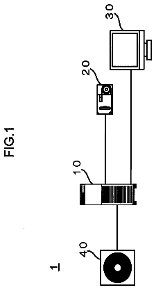
FIG. 1 illustrates a configuration example of a video system 100 including a video camera. The configuration example illustrated in FIG. 1 is also referred to as a video system 100 including a video camera according to the present disclosure later.
The video system 100 includes a video camera 101 and a personal computer (PC) 105.
The video camera 101 of the video system 100 includes therein a recording medium 102. However, the recording medium 102 is not necessarily to be fixed to the video camera 101, but may be a removable recording medium.
The video camera 101 starts a recording of a movie file containing video and audio in the recording medium 102 in response to a recording start command issued by a user pressing a recording start button 103. In this case, an SD card or a hard disk is often used as a specific example of the recording medium 102. As a file format of the video written in the recording medium 102, the MPEG4 (ISO/IEC 14496-12:2008) is often used in recent years due to its high compression efficiency. When the user presses the recording start button 103 again, a recording end command is issued. Thus, the video camera 101 ends the recording of the movie file.
The video camera 101 further includes a wireless transmitting unit 104. The wireless transmitting unit 104 performs a wireless communication by a wireless transmitting unit 107 included in the PC 105. The video camera 101 transmits movie data being recorded to the PC 105 in real time via the wireless transmitting unit 104. The movie being taken by the video camera 101 is displayed on a screen of the PC 105 as a streaming. Specific examples of the wireless transmitting units 104 and 107 include communication units complying to communication standards such as the wireless LAN (for example, Wi-Fi standards), the Bluetooth, the Worldwide Interoperability for Microwave Access (WIMAX), and the long term evolution (LTE). However, the transmission is not necessarily to be performed in a wireless manner, but can be performed via a wired connection complying with the Ethernet (trademark) standards or the USB standards.
The PC 105 records received movie data in a recording medium 106 included therein in conjunction with the recording start/end of the video camera 101. That is, movie data having the same content as the movie data recorded in the recording medium 102 of the video camera 101 is also recorded in the recording medium 106 of the PC 105. This is to improve the reliability by a redundant recording on one hand, and to eliminate time and effort to copy the movie file by inserting the recording medium 102 in the PC 105 after the recording ends on the other hand.
However, the inventors of the present disclosure found that the following two problems occur in this case.
The first problem found by the inventors of the present disclosure relates to an MPEG4 file format. In the MPEG4 file format defined by ISO/IEC 14496-12:2008, information in the file is stored by being divided in units called "BOX". For example, there are provided MOOV BOX for storing basic information including a size of a screen or a type of a codec and MDAT BOX for storing compressed video data and audio data. Representative types of the BOX are shown in Table 1.
TABLE-US-00001 TABLE 1 Type Function ftyp Always appear at the head of a file. Content is fixed depending on a type of the file. moov Store basic information on video and audio. A type of compression, the number of included audio channels, etc. Appear only once in the entire file by necessity. mdat Store multiplexed data entity of compressed video and audio. moof Store information required to demultiplex the multiplexed video and audio in mdat. Unnecessary when the same information is described in moov. free Content is ignored when playing video and audio. skip Content is ignored when playing video and audio.
In the MPEG4 file format, the compressed video data and audio data are stored in the MDAT BOX in a striping manner. That is, in this format, using only the information stored in the MDAT BOX, storage locations of the video data and the audio data cannot be determined. This is because separation information for separating the video data and the audio data is stored in a box other than the MDAT BOX. A player for playing the MPEG4 file separates and extracts the video data and the audio data from the MDAT BOX based on the separation information, and plays the video data and the audio data through a screen and a speaker, respectively.
In the MPEG 4 file format defined by ISO/IEC 14496-12:2008, two types of methods are mainly defined in order to store the separation information for separating the video data and the audio data. FIG. 2 illustrates a configuration example of the file format based on the first method, and FIG. 3 illustrates a configuration example of the file format based on the second method.
In the first method, the video data and the audio data are stored in a single MDAT BOX ("mdat" illustrated in FIG. 2), and all the separation information for separating the video data and the audio data is described in a MOOV BOX ("moov" illustrated in FIG. 2). Specifically, information on the multiplexing of the video and the audio is stored as information included below an STBL (Sample Table Box: Subclause 8.5 of ISO/IEC 14496-12:2008) included in the MOOV BOX.
When this method is used, the separation information for separating the video data and the audio data is collectively stored in a single place. Therefore, a random access to the video data and the audio data can be performed in a considerably easy manner. The reason is because it is promptly known which location of the MOOV BOX can enable an access to the corresponding video data in a predetermined time simply by interpreting a description in the MOOV BOX.
On the other hand, when this method is used, it is not possible for the video camera to generate an MPEG4 file to record in the recording medium of the video camera and simultaneously transmit the same data to a PC in real time to perform a streaming play of the video and the audio at the destination PC. The reason is because the MOOV BOX cannot be generated without determining all the separation information for separating the video data and the audio data, and hence the MOOV BOX is eventually placed at the tail of the movie file. For this reason, the destination PC cannot separate the video data and the audio data unless the movie file is all received. That is, the destination PC cannot play the movie file while receiving the movie file.
In the second method for storing the separation information for separating the video data and the audio data, as illustrated in FIG. 3, the video data and the audio data are stored in a plurality of MDAT BOXes ("mdat" illustrated in FIG. 3) in a divided manner, and the separation information for separating the video data and the audio data in each MDAT BOX is described in a MOOF BOX ("moof" illustrated in FIG. 3) paired with the MDAT BOX. Specifically, information on the multiplexing of the video and audio is stored as information included below a TRAF (Frack Fragment: Subclause 8.8.6 of ISO/IEC 14496-12:2008) included in the MOOF BOX. At this time, in the MOOV BOX, only basic information such as a size of a screen or a type of a codec is described, but the information on the separation of the video data and the audio data is not stored.
When this method is used, it is possible for the video camera to generate an MPEG4 file to record the movie data in the recording medium of the video camera and simultaneously transmit the same data to a PC in real time to perform a streaming play of the video and the audio at the destination PC. This is because the information on the separation of the video data and the audio data is sequentially transferred.
On the other hand, when this method is used, a random access to the video data and the audio data becomes rather complicated. This is because a reading of the separation information on the corresponding video data in a predetermined time requires interpreting the configuration of all BOXes from the head of the file, extracting only the MOOF BOXes, and reading the extracted MOOF BOXes one by one.
Summing up the above-mentioned aspects, it can be said that the file format by the first method (hereinafter referred to as "MPEG4 first format") is suitable for recording in a recording medium an MPEG4 file in which the movie data is stored. On the other hand, it can be said that the file format by the second method (hereinafter referred to as "MPEG4 second format") is suitable when transferring an MPEG4 file for performing a streaming play.
In other words, the MPEG4 first format needs to be adopted as a file format, with which the video camera 101 records the movie data in the recording medium 102, and on the other hand, the MPEG4 second format needs to be adopted as a file format for transferring a movie file to the PC 105 via the wireless transmitting unit 104.
However, one of the purposes of recording the movie file in the recording medium 106 of the PC 105 is to backup a movie file recorded in the recording medium 102 of the video camera 101, and hence the movie files recorded in the recording medium 102 and the recording medium 106 need to be exactly the same data in units of bit. In addition, it depends on the user's operation form which one of the movie file recorded in the recording medium 102 and the movie file recorded in the recording medium 106 takes a role of "backup".
There is no excess or deficiency in the video data and the audio data in both cases, and hence it is also possible to convert the file format from the MPEG4 second format into the MPEG4 first format. However, in the MPEG4 standards (ISO/IEC 14496-12:2008), a sequence of describing parameters in the MOOV BOX is not uniquely determined. In addition, there may be a plurality of ways to describe data of the same meaning, such as a CTTS (Composition Time to Sample: Subclause 8.6.1.3 of ISO/IEC 14496-12:2008) that is one of the pieces of information in the MOOV BOX. Therefore, even when a transferred movie file of the MPEG4 second format is converted into a movie file of the MPEG4 first format, it is not always the case that the same file as the movie file recorded on the video camera side in units of bit is generated.
In the case of the above-mentioned CTTS, when a value of "SAMPLE OFFET=1" is continued 10 times, "SAMPLE OFFET=1/SAMPLE COUNT=1" can be described 10 times, and alternatively, "SAMPLE OFFET=1/SAMPLE COUNT=10" can described only once. Both descriptions have the same meaning. However, the description contents differ from each other, and hence data amounts may differ from each other. Therefore, as described above, it is not always the case that the transmitted movie file is the same as the movie file obtained by converting the transmitted movie file in units of bit.
This means that a request for viewing a video of the movie data transferred from the video camera 101 on a screen of the PC 105 in real time to check the video and a request for setting the movie files recorded in the recording medium 102 and the recording medium 106 to be exactly the same as each other in units of bit cannot be compatible to each other depending on a standard MPEG4 file transfer and a simple file format conversion.
The second problem found by the inventors of the present disclosure relates to a transfer of a metafile associated with the movie file. Depending on the video camera, a movie file is recorded in a built-in recording medium in the MPEG4 file format, and at the same time, associated information on the movie is written in a separate file (hereinafter referred to as "metafile") and recorded in the same recording medium. The reason why such an operation is performed is because there is a need for leaving information that cannot be described in the standard MPEG4 file format together with the movie file. A video camera that performs such an operation includes, in particular, a video camera for professional use.
A specific example of the metafile is described with reference to FIG. 4 and Table 2.
FIG. 4 illustrates a configuration example of a file format of the metafile. As illustrated in FIG. 4, the metafile includes a header portion and a content portion. A data length of the header portion is 128 bytes. The content portion includes a plurality of blocks each having a data length of 96 bytes. Each block of 96 bytes of the content portion corresponds to one frame of a video included in the movie file, in which associated information on the frame is stored. That is, the first block of 96 bytes indicates the associated information on the first frame of the video included in the movie file, and the next block of 96 bytes indicates the associated information on the second frame of the video included in the movie file.
TABLE-US-00002 TABLE 2 Number of allocated Item bytes Meaning LTC 4 bytes LTC associated with frame LTC UB 4 bytes User Bit portion of LTC associated with frame VITC 4 bytes VITC associated with frame VITC UB 4 bytes User Bit portion of VITC associated with frame UMID 52 bytes Unique material identifier (UMID: SMPTE- 330M) of video file Reserved 28 bytes All set to zero
Table 2 shows information included in the content portion. The longitudinal time code (LTC) and the vertical interval time code (VITC) in Table 2 are parameters essential for identifying a frame of a video in the professional use. Further, the unique material ID (UMID: SMPTE330M) is only one ID in the world that is assigned to the frame. The UMID can include information on the latitude and the longitude when the frame is recorded.
When the video camera 101 records the above-mentioned metafile in the recording medium 102 together with the movie file, a need for recording the same metafile in the recording medium 106 of the PC 105 occurs naturally and necessarily. That is, how to transfer the metafile from the video camera 101 to the PC 105 becomes a problem. At this time, an attention needs to be paid in transferring a metafile while making it clear which movie file is paired with the metafile.
The inventors of the present disclosure found various problems described above, and created a configuration for solving the problems.
In the following, a recording apparatus according to the exemplary embodiments of the present disclosure is described. As the recording apparatus according to the embodiments, a video camera is described as an example.
[1. Configuration]
In the following, the video camera according to the present disclosure is described with reference to FIG. 5.
FIG. 5 illustrates a configuration of a video camera 500 according to this embodiment.
The video camera 500 includes an imaging element 501, a microphone 502, a sensor 503, a recording start/stop button 504, an H.264 encoder 505, an AAC encoder 506, a wireless transmitting unit 514, and a processor 550.
The imaging element 501 converts an imaging object into an electric signal. The microphone 502 converts an audio into an electrical signal. A signal output from the imaging element 501 is input to the H.264 encoder 505. The user instructs the video camera to start and end a recording via the recording start/stop button 504. Another example of the recording start/stop button 504 can be a recording switch provided on a main body of the video camera.
The H.264 encoder 505 and the AAC encoder 506 are hardware for encoding a video signal and an audio signal, respectively.
The processor 550 is, for example, an operating circuit implemented by an integrated circuit. The processor 550 is, for example, a single central processing unit (CPU). The processor 550 is configured to perform various processes in response to a computer program to be executed. By performing the processes simultaneously or sequentially, the processor 550 functions as if it were a different component. Each function of the processor 550 implemented by such a process is illustrated as a separate circuit or module in FIG. 5. That is, the processor 550 includes an MPEG4 first format muxer 507, an MPEG4 second format muxer 508, a metafile generating module 510, a MOOV BOX detecting circuit 511, a FREE BOX generating/adding circuit 512, a host controller 513, and part of the wireless transmitting unit 514.
As described above, in the present disclosure, there is described an example in which the separate circuit or module is denoted by a reference numeral, and operates as an independent component. As described above, a single processor 550 may be provided to operate as such circuits and modules. Note that, the module may be referred to as a circuit. Further, the circuit and the module may be implemented by hardware, software, or a combination of the hardware and the software.
Although it is described that the processor 550 includes a part of the wireless transmitting unit 514, which is intended that the processor 550 performs up to a process of preparing data to be transmitted. In order to actually transmit the data, a transmitting circuit including a modulating circuit and the like is required other than the processor 550. A configuration of the transmitting circuit is not an essence of the present disclosure, and hence a description thereof is omitted. A generally known transmitting circuit can be used.
The H.264 encoder 505 compresses the input video signal in an H.264 format (ISO/IEC 14496-10). At the same time, a signal output from the microphone 502 is input to the AAC encoder 506. The AAC encoder 506 compresses the input audio signal in an AAC format (ISO/IEC 14496-3).
The video camera 500 according to this embodiment includes two MPEG4 multiplexing circuits (muxers). One of the MPEG4 multiplexing circuits is the MPEG4 first format muxer 507. The MPEG4 first format muxer 507 has a function of storing video data and audio data in a single MPEG4 file format by multiplexing input video data and audio data in a single MDAT BOX and describing all information on the multiplexing in the MOOV BOX. The other is the MPEG4 second format muxer 508. The MPEG4 second format muxer 508 has a function of storing video data and audio data in a single MPEG4 file format by storing input video data and audio data in a plurality of MDAT BOXes in a divided manner and describing information on the multiplexing in each MDAT BOX in the MOOF BOX.
A method of storing the video data and the audio data in the plurality of MDAT BOXes in a divided manner by the MPEG4 second format muxer 508 includes a method of storing the video data and the audio data in a single MDAT BOX every time the video data and the audio data of a predetermined time (for example, 2 seconds) are obtained, a method of storing the video data and the audio data in a single MDAT BOX in units of group of pictures (GOP), and a method of storing the video data and the audio data in a single MDAT BOX every time a total size of the video data and the audio data reaches a predetermined size.
However, in this case, a multiplexing algorithm for multiplexing the video data and the audio data respectively input from the H.264 encoder 505 and the AAC encoder 506 needs to be exactly matched between the MPEG4 first format muxer 507 and the MPEG4 second format muxer 508. That is, both muxers need to be designed so that data obtained by sequentially combining contents of all the MDAT BOXes generated by the MPEG4 second format muxer 508 is exactly the same as contents of the single MDAT BOX generated by the MPEG4 first format muxer 507 in units of bit. That is, focusing only on the output MDAT BOX, the MPEG4 first format muxer 507 and the MPEG4 second format muxer 508 are designed so that the only difference between the MPEG4 first format muxer 507 and the MPEG4 second format muxer 508 is whether to store exactly the same stream data in which the video and the audio are multiplexed in the single MDAT BOX or in the plurality of MDAT BOXes in a sliced manner.
In addition, the MPEG4 first format muxer 507 is connected to a file format switch 509. This is to enable the user to select a file format output from the MPEG4 first format muxer 507 between a format completely complying to the MPEG4 (ISO/IEC 14496-12:2008) defined by the ISO and a QuickTime Movie format that is a file format similar to the MPEG4. Only a part of the contents described in the FTYP BOX and the MOOV BOX differs between the MPEG4 defined by the ISO and the QuickTime Movie format, and hence the muxer can be easily shared by the two formats. Therefore, the file format switch 509 is connected in the above-mentioned manner.
The compressed data of the video and the audio respectively output from the H.264 encoder 505 and the AAC encoder 506 is input to both the MPEG4 first format muxer 507 and the MPEG4 second format muxer 508.
An output of the MPEG4 first format muxer 507 passes through the MOOV BOX detecting circuit 511 and is input to the host controller 513. The MOOV BOX detecting circuit 511 has a function of detecting that the MPEG4 first format muxer 507 has generated the MOOV BOX and extracting the content of the BOX.
The host controller 513 has a function of recording input data in a recording medium 515 as a file by using a file system suitable for the recording medium 515. With this configuration, the video camera 500 according to this embodiment can record video captured by the imaging element 501 and audio captured by the microphone 502 in the recording medium 515 as a file of the MPEG4 first format.
On the other hand, an output of the MPEG4 second format muxer 508 passes through the FREE BOX generating/adding circuit 512 and is input to the wireless transmitting unit 514. A function of the FREE BOX generating/adding circuit 512 is described later.
The wireless transmitting unit 514 has a function of transferring input data to a receiving apparatus via a wireless LAN. Specifically, a method can be considered in which the input data is transferred to the receiving apparatus as a file by using, for example, a file transfer protocol (FTP: RFC765). A status of the file format switch 509 is also input to the wireless transmitting unit 514. This is to inform the receiving apparatus of the file format recorded in the recording medium 515 by the video camera. Specifically, when transferring the file via the FTP, for example, a method of setting an extension of the file to be transferred to MP4 (in the case of the MPEG4 format) or MOV (in the case of the QuickTime Movie format) can be considered. Although the wireless LAN is used as the network in this embodiment, it is not necessarily to be a wireless scheme, but a wired network can be used without causing any trouble in exerting the effect of the present disclosure. Further, the network itself is not necessarily to be an IP network, but the Bluetooth (trademark) or a simple serial signal transmission such as the USB can also be used.
An output of the sensor 503 is input to the metafile generating module 510. The sensor 503 is an element for acquiring information other than the video and the audio, and a specific example of the sensor 503 includes a clock (including a timecode generator), a global positioning system (GPS), and a circuit for acquiring a status of the video camera (such as a circuit for detecting a type of the recording medium 515 and a target bit rate set in the H.264 encoder 505).
The metafile generating module 510 shapes the input data into a predefined metafile format. Specifically, the metafile generating module 510 stores the input data in the file format described above with reference to FIG. 4. An output of the metafile generating module 510 is input to the host controller 513, and the host controller 513 writes the input information in the recording medium 515 as a file. At this time, a clear pairing with a video file recorded in the same recording medium is performed. For example, the metafile and the video file corresponding to each other are recorded in the recording medium 515 with exactly the same file name except for the extension. With this configuration, it becomes clear which metafile stores information on which video file.
[2. Operation]
Operations of the components of the video camera 500 configured in the above-mentioned manner are described below.
In the following, a specific operation of the FREE BOX generating/adding circuit 512 is described with reference to FIGS. 7 and 9. FIG. 7 illustrates a processing procedure performed by the FREE BOX generating/adding circuit 512.
Two types of data are input to the FREE BOX generating/adding circuit 512, the two types of data including an MPEG4 second format stream 701 output from the MPEG4 second format muxer 508 and a MOOV/metafile 702 output from the MOOV BOX detecting circuit 511 and the metafile generating module 510.
When the MOOV/metafile 702 is input, a type of the input data is determined (Step 703). This can be easily determined by checking which module the data is transferred from and content of the data itself. For example, when it is determined from the content of the data itself, if the data is a BOX of the MPEG4 file format, the type of the data can be determined from a character string stored in a range from the fifth byte to the eighth byte from the head of the data. If a character string of "moov" is stored in the range, it can be determined that the type of the data is a MOOV BOX. When the portion is a byte string that does not exist as an MPEG4 BOX name, it can be determined as a metafile.
Subsequently, the FREE BOX generating/adding circuit 512 determines a signature corresponding to the type of the input data. The signature is four ASCII characters indicating the type of the input data. Table 3 shows examples of the signature. For example, the signature is four characters of "moov" when the input data is a MOOV BOX. When the input data is a header portion of a metafile, the signature is four characters of "rmhd", and when the input data is a content portion of a metafile, the signature is four characters of "rmit". In addition, it can be considered that the input data is other than the MOOV BOX and the metafile as described later, and hence a signature unique to each case is defined as shown in Table 3.
TABLE-US-00003 TABLE 3 Signature Meaning rmhd Header portion of metafile rmit Fragment of content portion of metafile moov MOOV BOX used in MPEG4 first format mlen Size of mdat box in MPEG4 first format umid Unique material identifier (UMID: SMPTE-330M) of video file
Thereafter, the FREE BOX generating/adding circuit 512 generates a single FREE BOX complying with the MPEG4 file format standards (Step 705). A size of this BOX is a size obtained by adding 12 bytes to a size of the input MOOV/metafile 702. FIG. 8 illustrates a configuration example of the FREE BOX generated in Step 705. In the first four bytes, the size of the entire FREE BOX, i.e., a size obtained by adding 12 bytes to the size of the input MOOV/metafile 702, is written in BIG ENDIAN. The bytes from the fifth byte to the eighth byte are places for describing the type of the BOX, and hence four characters of "free" are described. In the subsequent bytes from the ninth byte to the twelfth byte, the signature selected in Step 704 is described. A size from the thirteenth byte to the end of the BOX is equal to the size of the input MOOV/metafile 702, and hence the input MOOV/metafile 702 is copied in this place as it is. With this configuration, a FREE BOX in which the input MOOV/metafile 702 is stored together with the signature indicating the type of the MOOV/metafile 702 can be generated. The FREE BOX generated in this manner includes information for reproducing the MOOV/metafile (reproduction information).
The generated FREE BOX is temporarily stored in a FREE BOX buffer in Step 710.
On the other hand, the FREE BOX generating/adding circuit 512 interprets a BOX configuration of the input MPEG4 second format stream, and constantly monitors whether or not the input stream includes a boundary of the BOX (Step 706). When there is not discontinuity in the BOX, the input MPEG4 second format stream is output as it is (Step 708). When the input stream includes the boundary of the BOX, it is checked whether or not the FREE BOX generated from the MOOV/metafile described above exists in the FREE BOX buffer in Step 710 (Step 707). When no FREE BOX exists in the FREE BOX buffer, a process of the next input MPEG4 second format stream is continued without performing any further process. When the FREE BOX exists in the FREE BOX buffer 710, the FREE BOX is output at a boundary portion of the BOX.
With the above-mentioned procedure, the FREE BOX generating/adding circuit 512 receives the MPEG4 second format stream. The upper part of FIG. 9 illustrates a configuration example of the input stream. The FREE BOX generating/adding circuit 512 then outputs an MPEG4 file in which the MOOV BOX extracted from the MPEG4 first format file and the FREE BOX that stores the content of the metafile are inserted. The lower part of FIG. 9 illustrates a configuration example of an output stream.
It is to be noted in this procedure that a boundary included between the MOOF BOX and the MDAT BOX needs to be ignored when detecting the boundary of the BOX in Step 706. It is because, when the FREE BOX is inserted between the MOOF BOX and the MDAT BOX, a distance between the MOOF BOX and the MDAT BOX is changed, and hence the information on the separation of the video data and the audio data described in the MOOF BOX becomes useless.
It is to be noted that the MPEG4 file output by the above-mentioned procedure also exactly complies with the MPEG4 second format. The content of the FREE BOX is ignored in a play operation of the video, and hence it does not affect the play of the video. That is, a player apparatus/player software supporting a play of the MPEG4 (ISO/IEC 14496-2008) can play the MPEG4 file illustrated in the lower part of FIG. 9 without having a problem. This enables a real-time viewing portion of the receiving apparatus described below to be generated in a considerably easy manner.
Although the MOOV is the only data extracted from the MPEG4 first format data in this embodiment, the present disclosure is not necessarily to be limited to this. For example, the MPEG4 first format muxer may uniquely extract a FREE BOX or a SKIP BOX to be added and input the extracted BOX to the FREE BOX generating/adding circuit. Both the FREE BOX and the SKIP BOX are BOXes for storing a type of data that is ignored at the time of playing the MPEG4 file. Alternatively, it can be considered to extract a size of the MDAT BOX in the MPEG4 first format, in order to reduce parameters to be calculated by the receiving apparatus as described below. A value of the size of the MDAT BOX can be calculated by obtaining a sum of the sizes of the MDAT BOXes appearing in the MPEG4 second format.
Although the video camera 500 that includes the wireless transmitting unit 514 and transmits the video data is referred to as "video camera" to simplify the description in this embodiment, it is not necessarily to be a so-called "video camera". That is, the data processed by the H.264 encoder 505 and the AAC encoder 506 is not necessarily to be directly input from the imaging element and the microphone, but even if the configuration is such that the video signal and the audio signal are input from an external connection terminal, such configuration causes no problem in exerting the effect of the present disclosure.
Subsequently, a receiving apparatus according to an embodiment of the present disclosure is described with reference to FIG. 6.
FIG. 6 illustrates a configuration of a receiving apparatus 600 according to this embodiment.
The description continues in the full USPTO document.
 Lapsed, fee not paid3 drawings