 Lapsed, fee not paid5 drawings
Hardware & Electronics · US 8,792,096 B2
Inspection apparatus for lithography
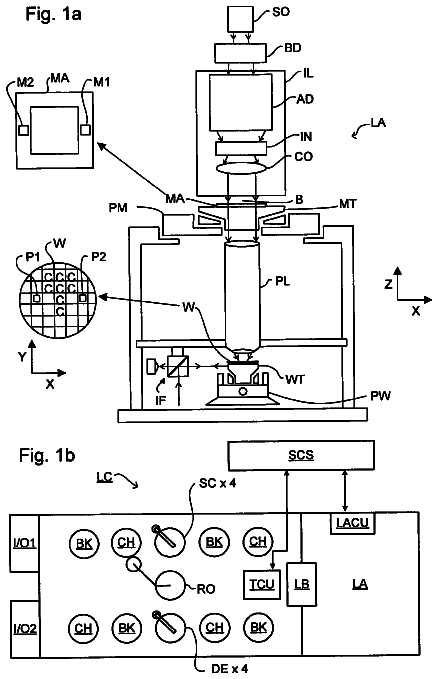
Four separately polarized beams are simultaneously measured upon diffraction from a substrate (W) to determine properties of the substrate.
US 8,792,121 B2 · Assignee: Hewlett-Packard Development Company, L.P. · Inventors: Henry; Shaun et al.
Sheet 1 of 4 from the published document. All sheets in the USPTO PDF
A method for controlling printing of a print job involves portioning the print job into a plurality of parts via a partition manager, and converting each part of the print job into respective binary image data parts via a Raster Image Processor (RIP) manager. The method further involves controlling a rate of aggregation of the converted parts via a throttle control manager. The rate of aggregation is controlled by monitoring parameters of a printing system used to perform the printing of the print job, determining that at least one of the monitored parameters reaches or exceeds a predefined threshold, and manipulating the rate of aggregation of the converted parts in response to the determining according to a throttle mode predefined for a particular set of monitored parameters.
The present disclosure relates generally to methods for controlling printing of a print job. Printing presses (e.g., a digital front end (DFE) press) may be used in various printing systems and/or organizations for high volume printing. These printers are often designed to handle large customer workflows such as, e.g., thousands of copies of full-color magazines or brochures. In some instances, the size and/or complexity of the customer print job associated with the workflow, as well as the job submission rate for a given workflow may overwhelm the printing system and consume some or even all of the system's resources. When this occurs, one may have to manually slow down the submission of print jobs to the printing system, or use an automated tool to gate the submission of print jobs to the printing system in order to conserve memory and/or other system resources.
1 of 4 drawing sheets so far from the published document, cropped to the drawing. Every sheet is in the USPTO PDF.
What the patent claimed, word for word. All of it is now free to use.
The present disclosure relates generally to methods for controlling printing of a print job.
Printing presses (e.g., a digital front end (DFE) press) may be used in various printing systems and/or organizations for high volume printing. These printers are often designed to handle large customer workflows such as, e.g., thousands of copies of full-color magazines or brochures. In some instances, the size and/or complexity of the customer print job associated with the workflow, as well as the job submission rate for a given workflow may overwhelm the printing system and consume some or even all of the system's resources. When this occurs, one may have to manually slow down the submission of print jobs to the printing system, or use an automated tool to gate the submission of print jobs to the printing system in order to conserve memory and/or other system resources.
Features and advantages of examples of the present disclosure will become apparent by reference to the following detailed description and drawings, in which like reference numerals correspond to similar, though perhaps not identical, components. For the sake of brevity, reference numerals or features having a previously described function may or may not be described in connection with other drawings in which they appear.
FIG. 1 schematically depicts an example of a system for controlling printing of a print job;
FIG. 2 is a flow diagram depicting an example of a method for controlling printing of a print job;
FIG. 3 is a logic flow diagram depicting an example of a method for controlling a rate of aggregation during the controlling of the printing of a print job;
FIG. 4 schematically depicts an example of a system for providing a notification message to a registered client of throttle-related event(s) occurring during the controlling of the printing of a print job; and
FIG. 5 schematically depicts another example of a system for controlling printing of a plurality of print jobs.
Improvement in the throughput of a high volume of print jobs (e.g., 150 to 600 print jobs per day) through a digital printing press may be accomplished, for example, by dividing each print job into multiple smaller parts, and supplying one or more of these smaller parts to various Raster Image Processor (RIP) engines. In this way, each print job of a customer's workflow is said to be RIPped in parallel. Since multiple RIP engines are being used during printing, it has been found that each RIPped printing job actually flows through the printing system much faster than when the whole print job is supplied to a single RIP engine. Afterwards, the RIPped print job is aggregated, or stitched back together so that a single digital printing press receives and prints a single print job.
Aggregation of the multiple parts of the print job may, in some instances, use a significant amount of system resources including Random Access Memory (RAM), hard disk space, and network bandwidth. In some cases, the amount of resources consumed during aggregation is such that the printing system may run out of those resources (e.g., RAM or hard disk space) and/or overwhelm the network. This situation may occur, for example, when several large volume workflows are partitioned (i.e., RIPped) in parallel and then aggregated before printing. When the printing system runs out of resources and/or the network is overwhelmed, the printing system may operate at a slower rate. Slower operation rates may starve the printing press of page data, potentially resulting in failed execution of print jobs because the printing press is not receiving the job pages at a print speed necessary for continuous printing by the press. In some cases, the printing system may crash when a certain amount of resources are consumed and/or when the network is severely overwhelmed.
Example(s) of the method as disclosed herein may be used to control printing of a print job by manipulating a rate of aggregation of partitioned print jobs until the printing system or organization has enough resources available for efficient and effective printing. As an example, efficient and effective printing may include the ability to RIP and print no slower than at a rated engine speed. For a high complexity print job, efficient and effective printing may include manipulating the rate of aggregation to achieve the highest possible rate of printing without starving the rest of the system of resources. The method disclosed herein uses real time data, such as a then-current amount of available RAM, a then-current amount of available hard disk space, and a network capacity that is then-currently being consumed by the whole printing system to control the aggregation rate. In some instances, the data may also be used along with heuristic information to determine when aggregation of RIPped print jobs should be started, paused, or allowed to complete.
Without being bound to any theory, it is believed that the examples of the method may also be used to prevent printing systems that use digital printing presses from being overloaded due, at least in part, to customers handling a high number of print jobs. When this occurs, a significant amount, if not all of the system resources may be consumed during printing, which may, in effect, reduce the overall throughput of print jobs. In an example, the printing system may be protected from being overloaded by prioritizing the usage of critical system resources based, at least in part, on a print job priority and a digital printing press priority. As such, the method of the instant disclosure provides, in part, for a print job processing pipeline that is reliable, stable, and enables maximized printing throughput even under heavily-loaded printing conditions (e.g., a high volume of print jobs).
Referring now to FIG. 1, an example of a printing system (identified by reference numeral 10) is depicted that may be used to perform examples of the method disclosed herein. The printing system 10 may be any system, scheme, or configuration including one or more printing devices or presses 24 for printing one or more print jobs 12. The printing system 10 depicted in FIG. 1 includes a single printing device 24, while other printing systems may include two, three, or more printing devices 24. For instance, in the example shown in FIG. 5 (which will be described in further detail below), another example of the printing system 10' includes four printing devices 24.sub.A, 24.sub.B, 24.sub.C, and 24.sub.D. Further, the printing device 24 of the printing system 10 may be chosen from any digital printer, web-fed printing press, sheet-fed printing press, packaging printers, labeling printers, clustered office printers, and/or offset printers capable of handling large customer workflows (which may include a large number of print jobs). In an example, the printing device is chosen from DFE presses such as those from the HP.RTM. Indigo 5500 Digital Press series or the HP.RTM. Indigo 7000 Digital Press series (both series being available from Hewlett-Packard Co., Palo Alto, Calif.).
The printing system 10 further includes a control system 11 associated with the printing device 24. The control system 11 may be embodied as one or several electronic processing devices, such as computer(s) that work in conjunction with a respective central processing unit (CPU) that performs the function of general-purpose computer(s). The control system 11 may otherwise be embodied as one or more application specific integrated circuit (ASIC), and is/are customized for the particular use or purpose of controlling the printing of print jobs submitted for printing. In either configuration, the control system 11 processor(s) and/or ASIC(s) may include software programs having computer readable code encoded on a non-transitory, tangible computer readable medium for performing various functions of the printing system 10, particularly for controlling printing of print jobs submitted to the printing system 10.
As shown in FIG. 1, the control system 11 includes, in part, a job submission manager 14, a RIP manager 16, a job partition manager 18, an aggregation manager 22, and a throttle control manager 26. Each of these managers 14, 16, 18, 22, and 26 may be embodied as one or more software programs executable by the control system 11 computer(s) for managing print job submission, print job partitioning, print job RIPping, print job aggregation, and print job manipulation (e.g., print job throttling), respectively. In another example, one or more of the managers 14, 16, 18, 22, and 26 is a software program executable by its own computer. Each of these managers 14, 16, 18, 22, and 26 is referred to herein as components of the control system 11, and details of each of the managers 14, 16, 18, 22, and 26 will be described below. It is to be understood that the managers 14, 16, 18, 22, and 26 are software programs that can reside on one or more computers, and that can be placed on the one or more computers in a variety of combinations such that overall system 10 performance is maximized.
The print job submission manager 14 is responsible for receiving print jobs (such as the print job 12 shown in FIG. 1) from one or more source computers or computing devices. The source computer may be any computing system or processor that may be used, e.g., by a user to initiate a print command. In instances where the printing system 10 is used in an organization where the source computer is part of a network of computers, the source computer may be a desktop computer, a laptop computer, an operator workstation (where several workstations may be run by a single processor, or each may have its own internal processor), and/or the like that is/are connected to the printing system 10 via a wired communication network, such as through a server (not shown). It is to be understood that the source computer may be a virtual machine operating in a host computer. In instances where the printing system 10 is located remotely from the source computer (e.g., the printing system 10 may be its own organization), the source computer may be a desktop computer or a mobile computing device such as a laptop computer, a notebook computer, a tablet computer, and/or the like that is/are connected to the printing system 10 wirelessly, such as via a Cloud. For wireless submission of the print job 12, the source computer may include a wireless modem containing its own software program(s) executing within the source computer.
The print job submission manager 14 may include software code for accepting print job(s), and placing the job contents/assets into the system 10 so that system resources (such as RIPS) may act upon those assets while processing the job into print ready data.
In an example, the print job submission manager 14 may receive one, two, three, or more print jobs from one or more of the source computers/computing devices. The print command used to initiate printing of the print job(s) may contain a command for printing one copy of the print job, or a command to print several copies of the print job. For high customer workflows, the job submission manager 14 may receive one or more print jobs, each requiring hundreds or possibly thousands of copies of each print job. Where several print jobs are submitted, the print job submission manager 14 may include software code for determining an initial, default priority of the print jobs, e.g., where the print jobs are positioned along a pipeline of jobs based on the time the individual print jobs are submitted. For example, if first, second, and third print jobs were submitted at 10:00 am, 10:01 am, and 10:02 am, respectively, the job submission manager 14 may organize the print jobs so that printing of the first print job has priority over second and third print jobs, and printing of the second print job has priority over the third print job, all based on the time that the print jobs were submitted. In another example, print jobs originating from a particular source computer may be given priority over print jobs from another source computer. Print job priority may also be organized according to a user-configurable default priority scheme, such as a scheme based on job type (PDF, XPS, PS, JPG, TIF, etc.), job size, number of color separations in the job, page size of the job, a deadline associated with the job, or any other job characteristic. In any of the examples disclosed herein, the print job priority may be set manually by the user, or automatically by an upstream controller (e.g., a JDF controller). The print job submission manager 14 may also place the job(s) into a processing queue with the proper priority and routing information. The routing information describes which press a job will be printed on in a multi-press environment.
The RIP manager 16 is a component of the printing system 10 that receives the print job 12 from the job submission manager 14. It is noted that, at this point, the print job 12 contains some type of digital data language, such as a concatenative programming language (e.g., PostScript or PS), an open standard document language (e.g., Portable Document Format or PDF), an open specification for page description language (e.g., Open XML Paper Specification or XPS), image formats (e.g., JPG, PNG, TIFF, Multi-Page TIFF, etc.), variable data formats (e.g., PPML, PDF/VT, Personalized JLYT, etc.), or the like. The RIP manager 16 determines a number of pages included in the print job 12, and based on this determination, further determines how the print job 12 should be partitioned (e.g., the number of parts into which the print job 12 is divided for submitting to the RIP engines, e.g., 20.sub.A and 20.sub.B of a particular pipeline).
As used herein, a "partition" or "part" with reference to a print job 12 refers to a subset of a total number of pages of the print job. Once the number of partitions has been determined, the RIP manager 16 may record the number in a database (shown by reference numeral 30 in FIG. 3) of the control system 11 that is used to track the status of the print job(s).
The RIP manager 16 also assigns the partitions of the print job 12 (once the print job 12 is actually partitioned by, e.g., the job partition manager 18) to one or more RIP engines that is/are associated with the pipeline for raster image processing. In the example shown in FIG. 1, the print job 12 is first partitioned by the job partition manager 18 into two parts 12.sub.P1 and 12.sub.P2, and these parts 12.sub.P1 and 12.sub.P2 may be sent to separate RIP engines 20.sub.A and 20.sub.B, respectively, assuming that the RIP engines 20.sub.A and 20.sub.B are then-currently available. In instances where the RIP engines 20.sub.A and 20.sub.B are not then-currently available (e.g., the engines may then-currently be occupied with another print job that preceded the print job 12), processing of the partitions 12.sub.P1 and 12.sub.P2 via the engines 20.sub.A and 20.sub.B is queued until the engines 20.sub.A and 20.sub.B are available to receive the respective partitions 12.sub.P1 and 12.sub.P2.
It is to be understood that the print job partition manager 18 is another component of the printing system 10 that, as previously mentioned, is responsible for receiving the print job from the RIP manager 16, and partitioning the print job 12 into the partitions (e.g., 12.sub.P1 and 12.sub.P2). In one example, partitioning may involve dividing a single document into a plurality of parts, where each part contains a preset number of pages. For example, if the print job contains a command to print a single copy of a document containing one thousand pages, then the job may, e.g., be divided into five parts, where each part contains two hundred pages of that document. As such, partitioning may be based on page ranges. It is to be understood that more complex partitioning may occur. For example, partitioning within a page containing variable data may be by asset type. In other examples, a job may be partitioned based on page content and/or complexity of the page content. In still other examples, a job may be partitioned by color pages versus monochrome pages.
When the RIP manager 16 assigns the partitions 12.sub.P1 and 12.sub.P2 (formed by the job partition manager 18 described above) to the engines 20.sub.A and 20.sub.B, respectively, the RIP manager 16 sends the assignment of the partitions 12.sub.P1 and 12.sub.P2 to the respective engines 20.sub.A and 20.sub.B. This assignment generally identifies a number of pages of the print job 12 that are to be RIPped by that particular engine. Also, when a partition 12.sub.P1, 12.sub.P2 has been assigned to a particular engine, a partition RIP status may be noted in the database 30 of the control system 11.
The RIP engines 20.sub.A and 20.sub.B receive the partition assignment from the RIP manager 16, and determine if a copy of the print job 12 is already available in a memory of the engine 20.sub.A, 20.sub.B. If so, the engine 20.sub.A, 20.sub.B will use the copy of the print job 12 to perform raster image processing on the partition received from the RIP manager 16. If a copy is not available, then the RIP engine 20.sub.A, 20.sub.B requests and receives a copy of the print job 12 from the RIP manager 16. The RIP engines 20.sub.A, 20.sub.B can then perform raster image processing on the respective partitions 12.sub.P1, 12.sub.P2. As such, each RIP engine 20.sub.A, 20.sub.B receives a copy of the print job 12 so that it can process the assigned partitions 12.sub.P1, 12.sub.P2 of the job 12.
The RIP engine 20.sub.A, 20.sub.B includes suitable software code for converting the language of the partition 12.sub.P1, 12.sub.P2 (which may be in PS, PDF, or some other language identified above) into binary image data parts. In an example, the RIP engines 20.sub.A, 20.sub.B produce a raster image, or bitmap of the respective parts (e.g., 12.sub.P1 and 12.sub.P2) of the print job 12 by converting the language of the print job into a high-resolution raster image suitable for printing via the digital printing press/printing device 24. After raster image processing, the partition 12.sub.P1, 12.sub.P2 is said to have been RIPped. After the partition 12.sub.P1, 12.sub.P2 has been RIPped, the respective RIP engine 20.sub.A, 20.sub.B sends a signal to the RIP manager 16 indicating that RIPping of the partitions 12.sub.P1, 12.sub.p2 has been completed. Upon receiving the notification, the RIP manager 16 may then update the database 30 of the control system 11.
In the example of FIG. 1, the print job 12 is partitioned into two parts 12.sub.P1 and 12.sub.P2, and two RIP engines 20.sub.A and 20.sub.B are available to receive the parts 12.sub.P1 and 12.sub.P2, respectively. It is to be understood that, in some instances, sufficient RIP engine resources may not be then-currently available to receive a partition of a print job. For instance, if the print job has four parts, and three engines are available, three of the four parts may be sent to respective engines, while the fourth part waits. In this case, the fourth part may be RIPped by the first RIP engine that becomes available after RIPping of one of the other three parts is complete. Once the individual parts 12.sub.P1, 12.sub.P2 are converted into raster images by the respective engines 20.sub.A, 20.sub.B (i.e., have been RIPped), an aggregation manager (or aggregator) 22 is used to stitch the print job 12 back together. More specifically, the aggregation manager 22 is a component of the system 10 that includes suitable software code for aggregating the plurality of RIPped parts (e.g., 12.sub.P1 and 12.sub.P2) of the print job 12 into a single part that represents a printable print job 12. This single part is then sent to the printing device 24 for printing.
As previously mentioned, the partitioning of the print job 12 may, in some instances, save at least some of the system resources so that the printing system 10 can handle higher volume workflows without being overwhelmed. It has been found, however, that aggregation of the partitioned print job may use a significant amount of system 10 resources, such as random access memory (RAM) and hard disk space. As such, in the absence of preventive countermeasures as disclosed herein, the system 10 may in some instances get overloaded (and potentially crash) when multiple large volume print jobs are being partitioned and processed in parallel (i.e., at substantially the same time).
In an example, the printing system 10 includes the throttle control manager 26. The throttle control manager 26 is a component of the system 10 that is responsible for monitoring system 10 parameters (e.g., operating system parameters, print system parameters, and/or print job parameters) in order to throttle (i.e., restrict the flow of information passing through the system 10) and to un-throttle (when previously throttled) selected components of the printing system 10 while processing one or more print jobs 12. The throttling of the component(s) of the system 10 is used to manipulate the rate of aggregation of a partitioned print job. As used herein, the term "throttling" means "slowing" from an unrestrained speed of operation. For instance, throttling may be used to decrease the rate of aggregation. It is to be understood that the decreasing of the aggregation rate is determined by the throttle control manager 26 on a case-by-case basis based, at least in part, on a then-current volume of print jobs and the amount of system resources that are then-currently available for printing.
Throttling may, for instance, be used to hold back aggregation of one or more print jobs until system resources become available. In these cases, the throttling may be based on an established priority for printing using real time and, in some instances, heuristic data. In this way, for instance, one print job may be aggregated and printed at a time to prevent using up most, or even all of the system's 10 resources during printing.
Throttling may be implemented in a variety of ways, such as by a system wide throttle, throttling of a subset of the system 10, throttling per print job, or by another predefined throttle mode. In a system wide throttle, the entire system 10 is throttled so that new print jobs are not accepted until the system wide throttle is released. In throttling of a subset of the system 10, selected components of the system 10 (such as, e.g., the job partitioning manager 16 and the RIP manager 18) are throttled so that print jobs accepted by the system 10 are not partitioned until the throttle is released. In throttling per print job, a selected print job accepted by the system 10 is throttled or held back so that other print jobs can be processed until the throttle is released.
Further, one or more throttling events (i.e., whenever throttling occurs) may take place at any given time during processing/printing of a print job 12. In an example, the throttle control manager 26 includes computer readable software code for performing the controlling of the printing of the print job 12, such as by throttling one or more components of the printing system 10, print jobs 12, etc.
It is to be understood that the throttle control manager 26 is capable of communicating with any of the system 10 components, including the job submission manager 14, the job partition manager 16, the RIP manager 18 and RIP engines 20.sub.A and 20.sub.B, and the aggregation manager 22. This is shown, e.g., by the double-headed arrows in FIG. 1. In instances where the throttle control manager 26 is embodied as a software program executable by a computer containing software programs representing each of the other system 10 components identified above, communication between the throttle control manager 26 and the other components 14, 16, 18, 20.sub.A, 20.sub.B, and 22 is accomplished internally to the computer. However, in instances where the throttle control manager 26 is embodied as its own processor or computer, the throttle control manager 26 may communicate with the other system 10 components 14, 16, 18, 20.sub.A, 20.sub.B, and 22 via i) a wired communication network where all of the components are connected to a server, or ii) wirelessly, e.g., via a Cloud. It is to be understood that any communication protocol may be used that is supported by the hardware, operating system, and software of the communicating components.
In an example, the computer upon which the throttle control manager 26 resides also includes communications equipment (not shown) that is capable of establishing at least data connections with remote devices and/or facilities. Generally, the computer includes appropriate communications hardware to support the functional and performance requirements of the system 10. Examples of the communications equipment may include a modem, TCP/IP supporting equipment, a wireless communication chipset, or the like. As will be described further below in conjunction with FIG. 4, the communications equipment may be used so that the throttle control manager 26 can establish appropriate connections with, e.g., the Internet, portable or stationary devices, computers connected to network associated with the printing system 10, or the like, and send notification messages to those devices, etc. These notification messages may be sent whenever a throttle-related event occurs during the examples of the method for controlling printing described in detail below.
An example of the method for controlling printing of a print job is generally shown in FIG. 2, and this example will now be described in conjunction with the system 10 described above in conjunction with FIG. 1. The method involves submitting the print job 12 to the printing system 10, as shown at 1000 in FIG. 2. The print job 12 is submitted to the printing system 10 from the source computer, examples of which were identified above. For instance, the user of the source computer may submit a command to the source computer to print the print job 12. The command may be submitted, for example, by selecting a print command on a graphical user interface (GUI), or by executing a program including a print command. Upon submission of the print command, the source computer sends a signal to the job submission manager 14 of the printing system 10. The submission manager 14 may, e.g., be a software program executable by a standalone computer or integrated into a printing system computer that executes software programs representing one or more other components (e.g., 16, 18, etc.) of the printing system 10.
When the print job 12 is submitted, the print job 12 is partitioned, as shown by reference numeral 1002 in FIG. 2. Partitioning is accomplished on command by the RIP manager 16, but the partitioning itself is performed by the job partition manager 18. In the example shown in FIG. 1, the print job 12 is divided or partitioned into two parts; part 12.sub.P1 and part 12.sub.P2. Partitioning may be accomplished, for example, according to a set of rules that the job partition manager 18 refers to during partitioning. These rules may be pre-programmed into the computer executing the software code of the job partition manger 18, and may be adjustable by an operator of the system 10 via re-programming or by overriding the rules. This may be accomplished, for example, utilizing a user interface associated with the job partition manager 18. In an example, the rules may be applied for real time data pertaining to the current workflow passing through the job partition manager 18 during partitioning.
After partitioning, the partitions (e.g., 12.sub.P1 and 12.sub.P2) are then sent to the RIP engines 20.sub.A and 20.sub.B, for converting the partitions into respective binary image data parts, as shown by reference numeral 1004 in FIG. 2. In other words, the partitions are sent to the engines 20.sub.A and 20.sub.B for RIPping.
After RIPping, the converted partitions 12.sub.P1 and 12.sub.P2 may be aggregated or stitched together prior to printing via the printing device 24. However, the method as disclosed herein controls a rate of aggregation of the converted partitions 12.sub.P1 and 12.sub.P2 of the print job 12. This is shown by reference numeral 1006 in FIG. 2. By controlling the rate of aggregation, it is believed that executing print jobs at a high throughput may be accomplished, for example, without consuming all of the resources of the system 10. It is further believed that examples of the disclosed method renders examples of the system 10 that are robust to high volume customer workflows.
An example of a method for controlling the rate of aggregation of the plurality of parts of a print job will be described below in conjunction with FIG. 3. It is to be understood that the various steps of the method for controlling the rate of aggregation are performed by the computer upon which the throttle control manager 26 resides, and are performed according to one or more software programs of the throttle control manager 26.
The controlling of the rate of aggregation includes monitoring parameters of the printing system (such as the system 10) being used to perform the printing of the print job 12. The monitoring of the printing system parameters may be accomplished periodically, such as every 30 seconds, every minute, every 5 minutes, or by any preset temporal value. Periodic monitoring may also be accomplished per print job, such as each time a new print job 12 is submitted to the printing system 10 for printing. In another example, the printing system 10 parameters are monitored in response to a trigger, such as system events. Examples of system events include a job 12 entering the system 10, a job 12 entering or exiting a given component or processing stage, a user interacting with the system 10, a real-time throttling notification which triggers other monitoring actions, or other system events.
In an example, during the monitoring, the throttle control manager 26 obtains parameters from various components/parts of the printing system 10, as shown by 300 in FIG. 3. The parameters may be obtained, for instance, upon request by the throttle control manager 26 from one or more components of the control system 11 (e.g., 14, 16, 18, etc.) and/or one or more components of other parts of the printing system 10. Examples of parameters from the other parts of the printing system 10 may include parameters pertaining to the system's 10 operating system, (such as a maximum memory, a then-current memory, an available memory, etc.), and parameters pertaining to the printing system/hardware (such as available hard disk space, available network input/output (I/O) bandwidth, available central processing unit (CPU) bandwidth, etc.). Other examples of parameters that may also be obtained include parameters pertaining to the print job itself, such as a number of print jobs in aggregation, the size of the print jobs in aggregation, a number and size of partitions of each print job, the size of new print jobs to be aggregated, etc. In the example depicted in FIG. 5, the parameters identified above are referred to default parameters 102, and the number of parameters may range from one to as many as desired in a single printing system 10. It is to be understood that there are a plurality of parameters that may be monitored, and the examples disclosed herein allow a user to add custom parameters (discussed further hereinbelow) and map the custom parameters to relevant components or job processing steps.
It is further to be understood that each of the default parameters 102 include predefined threshold values, and these values may be used, by the throttle control manager 26, to determine if a then-current reading of a parameter 102 (which is obtained by the throttle control manager 26) may affect the printing system 10. For example, if a reading received from one of the parameters 102 indicates that the network bandwidth has fallen below 20% of the threshold value, then the throttle control manager 26 may conclude that one or more of the RIP engines may have less CPU bandwidth for use during RIPping of a print job. This may, in effect, slow down RIPping of subsequent print jobs, and may further affect aggregation downstream from the RIP engine(s).
Other parameters that may be obtained and monitored by the throttle control manager 26 include user-selected, customized parameters 100. These parameters 100 are selected by a user (using, e.g., his/her personal computer, workstation, or the like), and may be used for a particular workflow. For instance, the user may select to control aggregation by, e.g., throttling the aggregator 22 so that aggregation of the print job submitted by the user is performed based on a number of pages in a partition or on the size of the partition. The user may customize this parameter, e.g., by selecting or entering a number into his/her personal computer or the like that represents an amount that the aggregator 22 is to be throttled.
Parameters may have threshold values or rules associated therewith. Customized parameters 100 may have customized thresholds, which may be determined, for example, in the field by technician(s) or user(s) who are familiar with the specific workflow, jobs and system configuration of a specific product installation. In an example, a user who has knowledge of the specific system and workflow can enter a threshold which he/she believes, based upon intuition or upon objective performance data, will aid the throttle control manager 26 in maintaining a high performance system for the user's particular workflow.
At step 302 in FIG. 3, the throttle control manager 26 obtains a list of components 104 to be monitored. In an example, there may be a default list of components 104 defined in the product by the manufacturer, which includes any components 104 that the manufacturer suggests monitoring. The default list may be altered by the user, which allows the user to configure his/her throttling approach based on his/her own workflow and job throughput volume. The user-defined list may identify that some, but not all, of the components 104 will be monitored, or it may identify that all of the components 104 will be monitored. It is generally desirable to monitor components 104 that may have some effect on the job throughput (e.g., those components 104 that have the potential to be bottlenecks). Examples of components to be monitored include the various components of the control system 11 (e.g., the RIP manager 16, the aggregator 22, etc.), as well as other components of the printing system 10 (e.g., hard disk, CPU, network, RAM, operating system, etc.). The components 104 may be monitored by active pinging driven from the throttle control manager 26, or the components 104 may be monitored via passive event reception where status events are generated by the various components in the system 10.
Then, at step 304, the throttle control manager 26 (via suitable software programs/routines) determines which of the parameters 100, 102 are applicable to, or correspond with which of the components 104 contained in the list. This process is referred to herein as component-parameter mapping. Then, upon making the determination at step 304, the throttle control manager 26 queries each of the components 104 for a parameter value, at step 306. This process repeats itself until all component-parameter mapping is understood by the manager 26. In other words, the throttle control manager 26 reads the component-parameter mapping and makes the persisted mapping (as stored in a file, database, etc.) into an operational/executable mapping where the throttle control manager 26 knows which parameters 100, 102 to query for each component 104. As such, the component-parameter mapping describes which parameters 100, 102 the throttle control manager 26 should monitor for a given component 104.
In an example, the component-parameter mapping occurs at throttle control manager 26 boot time. As such, this process may be an instantiation time process. In this example, this process sets up the throttle control manager 26 to be able to manage the system 10.
During component-parameter mapping, it may be assumed that all of the parameters 100, 102 represent a state of the system 10 at a given time. It may also or alternatively be assumed that a state of a sub-set of the system 10 or of a given system component 104 is represented by the parameters 100, 102 of the system, sub-set or component at any given point in time.
All of the information/data (e.g., parameters, parameter values, etc.) obtained at steps 300 through 304 is stored in the database 30 of the control system 11, as shown by reference numeral 308 in FIG. 3. Thereafter, the throttle control manager 26 determines (via suitable software programs/routines) if the operation of one or more components of the printing system 10 should be manipulated so that the rate of aggregation of the print job 12 may be controlled. In an example, the operation of the component(s) may be manipulated by determining, via the throttle control manager 26, if the component(s) should be throttled. In the example described herein in conjunction with FIG. 3, each component 104 or set of components 110 (i.e., a previously defined grouping of components, such as all of the components of the control system 11) is individually assessed, by the throttle control manager 26, to determine if that component 104 or set of components 110 should be throttled at step 310. The sets of components 110 may be defined by the manufacturer or by the user. In an example, the sets of components 110 are loaded from a persistent data source (file, database, etc.) during the instantiation of the throttle control manager 26. The throttle control manager 26 executes suitable software programs for i) determining if the component 104/set of components 110 require throttling (i.e., step 312), ii) throttling the component 104/set of component(s) 110 (i.e., step 314), and iii) sending a notification message to the user (i.e., step 316).
It is to be understood that each iteration of the software program (i.e., the determining, throttling, and sending) is performed for the single component 104 or set of components 110, and execution of the software program is repeated for a different component 104 or set of components 110. It is further to be understood that the execution of the software program may be repeated as many times as necessary so that the method may be applied for each component 104 or set of components 110 of the printing system 10.
The determination of whether or not a component 104 or set of components 110 should be throttled may be based, at least one part, on information stored in the database 30 from the component-parameter mapping, which includes the component-user-selected parameter mapping information 106 and the component-default parameter mapping information 108.
The description continues in the full USPTO document.
About 6,430 words. The USPTO PDF has it with every drawing.
Fees are due 3.5, 7.5 and 11.5 years after grant. This patent expired on July 29, 2026, so the fee marked "not paid" was the one that went unpaid.
METHOD FOR CONTROLLING PRINTING OF A PRINT JOB
Filed Oct 2011 · published Apr 2013Method for controlling printing of a print job
Filed Oct 2011 · granted Jul 2014Earlier publications, parents and continuations. None of them can still be enforced, or this patent would not be listed.
Prior art cited by the examiner or applicant. Useful when you check your own idea for novelty.
Everything on this page comes from the documents linked above.