 Lapsed, fee not paid4 drawings
Energy & Sustainability · US 8,790,833 B2
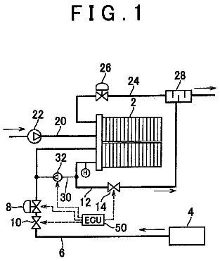
Floating-type microbial fuel cell
Provided is a floating-type microbial fuel cell capable of effectively generating energy from organic contaminants of contaminated waters.
US 8,790,846 B2 · Assignee: Panasonic Corporation · Inventors: Yamauchi; Masaki et al.
Sheet 1 of 6 from the published document. All sheets in the USPTO PDF
An object of the present invention is to provide a gas diffusion layer having gas flow passages formed at its one main surface, which is capable of achieving a further improvement in power generation performance. The fuel cell-use gas diffusion layer (14A, 14C) of the present invention has a double-layer structure made up of a first diffusion layer (15A, 15C) having gas flow passages (21A, 21C) at its one main surface, and a second diffusion layer (16A, 16C) disposed on the other main surface of the first diffusion layer. The first diffusion layer and the second diffusion layer are each structured with a porous member mainly comprised of conductive particles and a polymer resin, and the first diffusion layer is structured to be lower in porosity than the second diffusion layer.
A fuel cell, for example a polymer electrolyte fuel cell, is an apparatus that allows a fuel gas containing hydrogen and an oxidant gas containing oxygen such as air to electrochemically react with each other at a gas diffusion layer that has a catalyst layer such as platinum, such that electric power and heat are produced at the same time. FIG. 8 is a schematic diagram showing the basic structure of a conventional polymer electrolyte fuel cell. A single cell (also referred to as a cell) 100 of the polymer electrolyte fuel cell includes a membrane electrode assembly 110 (hereinafter referred to as the MEA: Membrane-Electrode-Assembly) and paired plate-like electrically conductive separators 120 disposed on the opposite faces of the MEA 110, respectively. The MEA 110 includes a polymer electrolyte membrane (a resin ion exchange membrane) 111 that selectively transports hydrogen ions, and
1 of 6 drawing sheets so far from the published document, cropped to the drawing. Every sheet is in the USPTO PDF.
What the patent claimed, word for word. All of it is now free to use.
The present invention relates to a fuel cell that uses a liquid fuel such as pure hydrogen, methanol or the like, or a reducing agent such as reformed hydrogen obtained from a fossil fuel as a fuel gas, and that uses air (oxygen) as an oxidant gas. More specifically, the present invention relates to a gas diffusion layer included in the fuel cell and a process for production thereof.
A fuel cell, for example a polymer electrolyte fuel cell, is an apparatus that allows a fuel gas containing hydrogen and an oxidant gas containing oxygen such as air to electrochemically react with each other at a gas diffusion layer that has a catalyst layer such as platinum, such that electric power and heat are produced at the same time.
FIG. 8 is a schematic diagram showing the basic structure of a conventional polymer electrolyte fuel cell. A single cell (also referred to as a cell) 100 of the polymer electrolyte fuel cell includes a membrane electrode assembly 110 (hereinafter referred to as the MEA: Membrane-Electrode-Assembly) and paired plate-like electrically conductive separators 120 disposed on the opposite faces of the MEA 110, respectively.
The MEA 110 includes a polymer electrolyte membrane (a resin ion exchange membrane) 111 that selectively transports hydrogen ions, and paired electrode layers 112 formed at the opposite faces of the polymer electrolyte membrane 111. The paired electrode layers 112 are formed at the opposite faces of the polymer electrolyte membrane 111, and each include a catalyst layer 113 which is mainly comprised of carbon powder bearing a platinum metal catalyst, and a gas diffusion layer 114 that is formed on the catalyst layer 113 and that has combined features of current-collecting effect, gas permeability, and water repellency. The gas diffusion layer 114 is structured with a porous base material 115 made of carbon fibers, and a coating layer (a water-repellent carbon layer) 116 made of carbon and a water-repellent member.
The paired separators 120 are provided with, at their main surfaces abutting on the gas diffusion layers 114, respectively, fuel gas flow passages 121 for allowing the fuel gas to flow through, and oxidant gas flow passages 122 for allowing the oxidant gas to flow through. Further, the paired separators 120 are provided with coolant flow channels 123 through which coolant or the like flows through. Supply of the fuel gas and the oxidant gas to the paired electrode layers 112 through the gas flow passages 121 and 122, respectively, causes an electrochemical reaction, to produce electric power and heat.
As shown in FIG. 8, the cell 100 structured as described above is generally used by being stacked by one piece or more, so that the cells 100 adjacent to each other are electrically connected in series. It is noted that, here, the cells 100 stacked together are fastened under pressure at a prescribed fastening pressure by fastening members 130 such as bolts, so as to prevent leakage of the fuel gas and the oxidant gas, which are the reactant gas, and to reduce the contact resistance. Accordingly, each of the MEAs 110 and each of the separators 120 are brought into plane-to-plane contact at a prescribed pressure. Here, the separators 120 have a current collecting ability for electrically connecting adjacent ones of the MEAs 110 and 110 in series. Further, in order to prevent the gases required for the electrochemical reaction from leaking externally, sealing members (gaskets) 117 are disposed between the paired separators 120 and 120 so as to cover the side surfaces of the catalyst layer 113 and the gas diffusion layer 114.
In recent years, in the field of the fuel cell, there is a demand for a further reduction in costs. Accordingly, from the viewpoint of a reduction in the unit price of the constituents and in the number of components, various techniques for achieving a reduction in costs have been proposed. One of such proposals is a technique of providing the gas flow passages at the gas diffusion layer, instead of at the separator.
In the conventional fuel cell shown in FIG. 8, the gas flow passages are provided at each of the separators. A method of implementing such a structure is to use, e.g., carbon and resin, as the material of each separator, and subjecting them to injection molding using a mold having concavity and convexity corresponding to the shape of the gas flow passages. However, in this case, there is an issue of the high production cost. Further, another method of implementing such a structure is to use metal as the material of each separator, and to roll the metal using a mold having concavity and convexity corresponding to the shape of the gas flow passages. However, in this case, though a reduction in cost can be realized as compared to the injection molding, there is an issue that the separator is prone to corrode, which in turn impairs the power generation performance as the fuel cell.
On the other hand, the gas diffusion layer is structured with a porous member, such that it possesses gas diffusibility. Accordingly, it is easier to form the gas flow passages at the gas diffusion layer than forming them at the separator, and is advantageous in reducing the cost and in achieving higher power generation performance. For example, Patent Documents 1 to 3 each disclose a gas diffusion layer having such a structure.
Patent Document 1 discloses the following technique: using a molding jig provided with a plurality of flow channel molds each elongated in a rectangular parallelepiped form, molding a porous member whose base material is carbon fibers by a paper-making method; and thereafter, by removing the molding jig, forming gas flow passages inside the gas diffusion layer.
Patent Document 2 discloses the following technique: patterning partition walls made of resin or metal which are to form the gas flow passages on a separator; and thereafter, shaping a porous member whose base material is carbon fibers so as to cover the partition walls, to form the gas flow passages at a gas diffusion layer.
Patent Document 3 discloses the following technique: disposing a flow channel structuring member made of carbon paper provided with a gas flow passages structure by punching or the like between a porous member whose base material is carbon fibers, and a flat plate-like separator, to form gas flow passages at a gas diffusion layer.
Further, as disclosed in the aforementioned Patent Documents 1 to 3, the gas diffusion layer is generally structured with a porous member whose base material is carbon fibers. However, the porous member whose base material is carbon fibers involves complicated production steps and requires a considerable production cost, and hence, it is expensive. Accordingly, a technique has been proposed to achieve a reduction in costs of the fuel cell by structuring a gas diffusion layer without using the porous member whose base material is carbon fibers. As the gas diffusion layer of such a structure, for example, Patent Document 4 discloses one.
Patent Document 4 discloses a technique of structuring a gas diffusion layer by mixing graphite, carbon black, uncalcined PTFE (polytetrafluoroethylene), and calcined PTFE, without using carbon fibers as the base material.
Patent Documents
Patent Document 1: Japanese Unexamined Patent Publication No. 2006-339089 Patent Document 2: Japanese Unexamined Patent Publication No. 2005-294121 Patent Document 3: Japanese Unexamined Patent Publication No. 2000-123850 Patent Document 4: Japanese Unexamined Patent Publication No. 2003-187809
Subject to be Solved by the Invention
In a case where the gas diffusion layer is structured with a porous member whose base material is carbon fibers, as can be seen in the aforementioned Patent Documents 1 to 3, normally, its porosity exhibits a high value of 80% or more. Accordingly, when the gas flow passages are formed at the gas diffusion layer, the reactant gas may disadvantageously permeate (shortcut) through rib portions that each partition between adjacent ones of the gas flow passages. That is, the fuel gas or the oxidant gas may not flow in accordance with the shape of the gas flow passages from the upstream portion to the downstream portion of the gas flow passages. This may impair the gas diffusibility, which may invite a reduction in power generation performance.
Further, with the structure of Patent Document 2, the partition walls prevent the reactant gas from permeating through the rib portions. However, in a case where the partition walls are formed with resin, the electrical conductivity is impaired, which invites an increase in IR loss. On the other hand, in a case where the partition walls are formed with metal, a side reaction becomes likely to occur, and the durability of the polymer electrolyte membrane reduces. That is, consequently, the power generation performance may be impaired.
On the other hand, as disclosed in Patent Document 4, in a case where the gas diffusion layer is structured without using the carbon fibers as the base material, the porosity can be suppressed to be lower than 80%. Accordingly, it is possible to prevent the reactant gas from permeating through the rib portions. However, a gas diffusion layer structured without using carbon fibers as the base material (hereinafter, such a gas diffusion layer is referred to as the base material-less gas diffusion layer) faces an issue of being low in strength. Accordingly, in a case where the gas flow passages are formed at the base material-less gas diffusion layer by rolling or the like, the rib portions each partitioning adjacent ones of the gas flow passages may deform by, e.g., a pressure being applied to the cell when it is assembled. This may invite an excessive reduction in cross-sectional area of the gas flow passages.
The strength of the base material-less gas diffusion layer can be enhanced by reducing the porosity (i.e., increasing the density). However, in this case, the gas diffusibility is impaired. In particular, the reactant gas cannot reach the catalyst layer vertically below the rib portions, and an in-plane power generation distribution varies, resulting in a voltage drop. That is, consequently, the power generation performance is impaired.
Accordingly, an object of the present invention is to improve the aforementioned issues, and to provide a gas diffusion layer that has gas flow passages formed at one main surface, and that is capable of achieving a further improvement in power generation performance, and to provide a process for production thereof, and a fuel cell including the gas diffusion layer.
Means for Solving the Subject
In order to achieve the aforementioned object, the present invention is provided with the following arrangements.
According to a first aspect of the present invention, there is provided a gas diffusion layer used for fuel cell, wherein
the gas diffusion layer has a double-layer structure made up of a first diffusion layer and a second diffusion layer, the first diffusion layer having a gas flow passage formed at one main surface of the first diffusion layer, and the second diffusion layer being stacked on an other main surface of the first diffusion layer,
the first and second diffusion layers are each structured with a porous member mainly comprised of conductive particles and a polymer resin, and
the first diffusion layer is lower in a porosity than the second diffusion layer.
As used herein, the "porous member mainly comprised of conductive particles and a polymer resin" refers to a porous member having a structure supported by the conductive particles and the polymer resin, without use of carbon fibers as the base material (what is called a self-supporting structure). In a case where a porous member is structured with the conductive particles and the polymer resin, as will be described later, for example, a surfactant and a dispersing solvent are used. In this case, during the course of production, the surfactant and the dispersing solvent are removed by calcination. However, the surfactant and the dispersing solvent may not fully be removed, and may remain in the porous member. Accordingly, so long as it is a self-supporting structure which does not use carbon fibers as the base material, the porous member may contain the remained surfactant and the dispersing solvent. Further, so long as it is a self-supporting structure which does not use carbon fibers as the base material, the porous member may include other materials.
According to a second aspect of the present invention, there is provided the gas diffusion layer according to the first aspect, wherein the first and second diffusion layers are each structured with a porous member mainly comprised of the conductive particles and the polymer resin, with carbon fibers added by a weight smaller than a weight of the polymer resin.
According to a third aspect of the present invention, there is provided the gas diffusion layer according to the second aspect, wherein the carbon fibers are any one of vapor grown carbon fibers, milled fibers, and chopped fibers.
According to a fourth aspect of the present invention, there is provided the gas diffusion layer according to any one of the second and third aspects, wherein the first diffusion layer is higher in a composition ratio of the carbon fibers than the second diffusion layer.
According to a fifth aspect of the present invention, there is provided the gas diffusion layer according to any one of the first to fourth aspects, wherein the conductive particles contained in the first diffusion layer are structured with carbon materials of two types or more differing from each other in an average particle size.
According to a sixth aspect of the present invention, there is provided the gas diffusion layer according to any one of the first to fifth aspects, wherein the first diffusion layer is lower in a composition ratio of the polymer resin than the second diffusion layer.
According to a seventh aspect of the present invention, there is provided the gas diffusion layer according to any one of the first to sixth aspects, wherein the porosity of the first diffusion layer is 20% or more and less than 50%.
According to an eighth aspect of the present invention, there is provided the gas diffusion layer according to any one of the first to seventh aspects, wherein the porosity of the second diffusion layer is 65% or more and less than 80%.
According to a ninth aspect of the present invention, there is provided a fuel cell, comprising:
a polymer electrolyte membrane;
paired catalyst layers opposing to each other having the polymer electrolyte membrane interposed therebetween;
paired gas diffusion layers opposing to each other having the polymer electrolyte membrane and the paired catalyst layers interposed therebetween; and
paired collector plates opposing to each other having the polymer electrolyte membrane, the paired catalyst layers, and the paired gas diffusion layers interposed therebetween, wherein
at least one of the paired gas diffusion layers is the gas diffusion layer according to any one of the first to eighth aspects, and
the first diffusion layer contacts the collector plate, and the second diffusion layer contacts the catalyst layer.
According to an 10th aspect of the present invention, there is provided a fuel cell, comprising:
a polymer electrolyte membrane;
an anode catalyst layer formed on one main surface of the polymer electrolyte membrane;
an anode gas diffusion layer stacked on the anode catalyst layer;
a separator stacked on the anode gas diffusion layer, having a gas flow passage formed at a main surface of the separator that contacts the anode gas diffusion layer;
a cathode catalyst layer formed on an other main surface of the polymer electrolyte membrane;
a cathode gas diffusion layer stacked on the cathode catalyst layer; and
a collector plate stacked on the cathode gas diffusion layer, wherein
the cathode gas diffusion layer is the gas diffusion layer according to any one of the first to eighth aspects, and
the first diffusion layer contacts the collector plate, and the second diffusion layer contacts the catalyst layer.
According to an 11th aspect of the present invention, there is provided a process for production of a gas diffusion layer used for a fuel cell, comprising:
preparing two sheet-like porous members differing from each other in a porosity;
of the prepared two porous members, disposing a porous member whose porosity is lower in a mold having a projection portion corresponding to a shape of a gas flow passage, and thereafter, performing rolling so as to form the gas flow passage at one main surface of the porous member whose porosity is lower; and
stacking and bonding a porous member whose porosity is higher on an other main surface of the porous member whose porosity is lower and having the gas flow passage formed.
According to a 12th aspect of the present invention, there is provided a process for production of a gas diffusion layer used for a fuel cell, comprising:
preparing two sheet-like porous members differing from each other in a porosity;
stacking the prepared two porous members; and
disposing the stacked two porous members in a mold having a projection portion corresponding to a shape of a gas flow passage, such that a porous member whose porosity is lower faces the projection portion, and thereafter, performing rolling so as to form the gas flow passage at one main surface of the porous member whose porosity is lower.
Effects of the Invention
In connection with the fuel cell-use gas diffusion layer of the present invention, the gas diffusion layer has a double-layer structure made up of the first diffusion layer and the second diffusion layer. The first diffusion layer having gas flow passages formed is set to be lower in porosity than the second diffusion layer. That is, the strength of the first diffusion layer is set to be higher than that of the second diffusion layer. This makes it possible to prevent the rib portions each partitioning adjacent ones of the gas flow passages from deforming by a pressure applied, e.g., when a plurality of cells are stacked and fastened under pressure, which may otherwise invite closure of the gas flow passages. Further, it is possible to prevent the reactant gas from permeating through the rib portions, and to allow the reactant gas to flow at a constant flow rate from the upstream portion to the downstream portion of the gas flow passages in accordance with the shape of the gas flow passages. Further, because the second diffusion layer is higher in porosity than the first diffusion layer, the gas diffusibility of the second diffusion layer allows the reactant gas to diffuse vertically below the rib portions also, which in turn suppresses variations in the in-plane power generation distribution.
Accordingly, a further improvement in power generation performance can be achieved. Further, the first and second diffusion layers are each structured with a porous member mainly comprised of conductive particles and a polymer resin, a reduction in costs can be achieved, and the gas flow passages of a complicated shape can be formed with ease.
These and other objects and features of the present invention will become clear from the following description taken in conj unction with the preferred embodiments thereof with reference to the accompanying drawings, in which:
FIG. 1 is a schematic cross-sectional view showing the basic structure of a fuel cell according to an embodiment of the present invention;
FIG. 2 is a schematic cross-sectional view showing the structure of a gas diffusion layer alone according to the embodiment of the present invention;
FIG. 3 is a flowchart showing a process for production of the gas diffusion layer according to the embodiment of the present invention;
FIG. 4A is a schematic explanatory diagram showing the process for production of the gas diffusion layer according to the embodiment of the present invention;
FIG. 4B is a schematic explanatory diagram showing a step following FIG. 4A;
FIG. 4C is a schematic explanatory diagram showing a step following FIG. 4B;
FIG. 5 is a flowchart showing another process for production of the gas diffusion layer according to the embodiment of the present invention;
FIG. 6A is a schematic explanatory diagram showing another process for production of the gas diffusion layer according to the embodiment of the present invention;
FIG. 6B is a schematic explanatory diagram showing a step following FIG. 6A;
FIG. 6C is a schematic explanatory diagram showing a step following FIG. 6B;
FIG. 7 is a schematic cross-sectional view showing a variation of the basic structure of the fuel cell according to the embodiment of the present invention; and
FIG. 8 is a schematic cross-sectional view showing the structure of a conventional fuel cell.
In the following, with reference to the drawings, a description will be given of an embodiment of the present invention. It is noted that, throughout the drawings referred to in the following, identical reference symbols are allotted to identical or corresponding parts, and description thereof will not be repeated.
<<Embodiment>>
FIG. 1 is a schematic cross-sectional view showing the basic structure of a fuel cell according to the embodiment of the present invention. The fuel cell according to the present embodiment is a polymer electrolyte fuel cell that allows a fuel gas containing hydrogen and an oxidant gas containing oxygen such as air to electrochemically react with each other, such that electric power and heat are generated at the same time. It is noted that the present invention is not limited to the polymer electrolyte fuel cell, and is applicable to various fuel cells.
In FIG. 1, the fuel cell according to the present embodiment includes a cell (single cell) 1 that includes a membrane electrode assembly 10 (hereinafter referred to as the MEA), and paired flat plate-like collector plates 20A and 20C possessing electrical conductivity and disposed on opposite faces of the MEA 10, respectively. It is noted that the fuel cell according to the present embodiment may be structured by stacking a plurality of pieces of the cells 1. In this case, the cells 1 stacked together are preferably fastened under pressure at a prescribed fastening pressure by fastening members (not shown) such as bolts, so as to prevent leakage of the fuel gas and the oxidant gas and to reduce the contact resistance.
The MEA 10 includes a polymer electrolyte membrane 11 that selectively transports hydrogen ions, and paired electrode layers formed on opposite faces of the polymer electrolyte membrane 11, respectively. One of the paired electrode layers is an anode electrode (also referred to as the fuel electrode) 12A, and the other is a cathode electrode (also referred to as the air electrode) 12C. The anode electrode 12A is formed on one face of the polymer electrolyte membrane 11, and includes an anode catalyst layers 13A mainly comprised of carbon powder bearing a platinum metal catalyst, and an anode gas diffusion layer 14A that is formed on the anode catalyst layer 13A and that has combined features of current-collecting effect, gas permeability, and water repellency. The cathode electrode 12C is formed on the other face of the polymer electrolyte membrane 11, and includes an cathode catalyst layers 13C mainly comprised of carbon powder bearing a platinum metal catalyst, and a cathode gas diffusion layer 14C that is formed on the cathode catalyst layer 13C and that has combined features of current-collecting effect, gas permeability, and water repellency.
The anode gas diffusion layer 14A is structured with a double-layer structure made up of a first anode diffusion layer 15A which is one example of a first diffusion layer, and a second anode diffusion layer 16A which is one example of a second diffusion layer. The first and second anode diffusion layers 15A and 16A are each structured with a base material-less gas diffusion layer in which carbon fibers are not used as the base material. Specifically, the first and second anode diffusion layers 15A and 16A are each structured with a porous member mainly comprised of conductive particles and a polymer resin. The first anode diffusion layer 15A is provided with, at its one main surface, fuel gas flow passages 21A for allowing the fuel gas to flow through. The tip of each rib portion 22A partitioning adjacent ones of the fuel gas flow passages 21A and 21A is brought into contact with the collector plate 20A at a prescribed pressure. This prevents the fuel gas from leaking outside the fuel gas flow passages 21A (external leakage) . The other main surface of the first anode diffusion layer 15A contacts the second anode diffusion layer 16A. The first anode diffusion layer 15A is structured to be lower in porosity than the second anode diffusion layer 16A. The second anode diffusion layer 16A contacts the anode catalyst layer 13A.
The cathode gas diffusion layer 14C is structured with a double-layer structure made up of a first cathode diffusion layer 15C which is one example of a first diffusion layer, and a second cathode diffusion layer 16C which is one example of a second diffusion layer. The first and second cathode diffusion layers 15C and 16C are each structured with the base material-less gas diffusion layer in which carbon fibers are not used as the base material. Specifically, the first and second cathode diffusion layers 15C and 16C are each structured with a porous member mainly comprised of conductive particles and a polymer resin. The first cathode diffusion layer 15C is provided with, at its one main surface, oxidant gas flow passages 21C for allowing the oxidant gas to flow through. The tip of each rib portion 22C partitioning adjacent ones of oxidant gas flow passages 21C and 21C is brought into contact with the collector plate 20C at a prescribed pressure. This prevents the oxidant gas from leaking outside the oxidant gas flow passage 21C (external leakage). The other main surface of the first cathode diffusion layer 15C contacts the second cathode diffusion layer 16C. The first cathode diffusion layer 15C is structured to be lower in porosity than the second cathode diffusion layer 16C. The second cathode diffusion layer 16C contacts the cathode catalyst layer 13C.
Supply of the fuel gas to the anode electrode 12A through the fuel gas flow passage 21A and supply of the oxidant gas to the cathode electrode 12C through the oxidant gas flow passage 21C cause an electrochemical reaction, to produce electric power and heat.
It is noted that, when the cell 1 is fastened under pressure by fastening members (not shown) such as bolts in order to prevent leakage of the reactant gas and to reduce a contact resistance, it is preferable that the fastening pressure is 2 to 10 kgf/cm.sup.2. In a case where the fastening pressure is greater than 10 kgf/cm.sup.2, the rib portions 22A and 22C are prone to deform. On the other hand, in a case where the fastening pressure is smaller than 2 kgf/cm.sup.2, a contact resistance between the members sharply rises, or the fuel gas or the oxidant gas would not easily flow through the fuel gas flow passages 21A or the oxidant gas flow passages 21C.
The collector plates 20A and 20C are structured with a material such as metal possessing low gas permeability. Preferably, the collector plates 20A and 20C are structured with a material such as carbon, metal or the like which possesses excellent corrosion resistance, electrical conductivity, gas impermeability, and flatness. It is noted that, coolant flow channels (not shown) for allowing coolant or the like to flow through may be provided at the collector plates 20A and 20C.
In order to prevent leakage of the fuel gas to the outside, anode gaskets 17A are provided as sealing members between the collector plate 20A and the polymer electrolyte membrane 11, so as to cover the side surfaces of the anode catalyst layer 13A and the anode gas diffusion layer 14A. Further, in order to prevent leakage of the oxidant gas to the outside, cathode gaskets 17C are provided as sealing members between the collector plate 20C and the polymer electrolyte membrane 11, so as to cover the side surfaces of the cathode catalyst layer 13C and the cathode gas diffusion layer 14C.
As the material of the anode gaskets 17A and the cathode gaskets 17C, general thermoplastic resin, thermosetting resin or the like can be used. For example, as the material of the anode gaskets 17A and the cathode gaskets 17C, silicone resin, epoxy resin, melamine resin, polyurethane based resin, polyimide based resin, acrylic resin, ABS resin, polypropylene, liquid crystal polymer, polyphenylene sulfide resin, polysulfone, glass fiber reinforced resin or the like can be used.
It is noted that, the anode gaskets 17A and the cathode gaskets 17C are preferably partially impregnated with the circumferential portion of the anode gas diffusion layer 14A or the cathode gas diffusion layer 14C. This makes it possible to improve the power generation durability and the strength.
Further, instead of the anode gaskets 17A and the cathode gaskets 17C, gaskets may be disposed between the collector plate 20A and the collector plate 20C, so as to cover the side surfaces of the polymer electrolyte membrane 11, the anode electrode 12A, and the cathode electrode 12C. This makes it possible to prevent degradation of the polymer electrolyte membrane 11, and to improve the handleability of the MEA 10 and the workability in mass production.
Next, a further detailed description will be given of the structure of the anode gas diffusion layer 14A and the cathode gas diffusion layer 14C according to the present embodiment. Here, unless otherwise noted, the anode gas diffusion layer 14A and the cathode gas diffusion layer 14C are identically structured. Therefore, when a description is given to any matter common to them, they are simply referred to as the gas diffusion layer 14. Further, the first anode diffusion layer 15A and the first cathode diffusion layer 15C are referred to as the first diffusion layer 15; and the second anode diffusion layer 16A and the second cathode diffusion layer 16C is referred to as the second diffusion layer 16. Further, the fuel gas flow passages 21A and the oxidant gas flow passages 21C are referred to the gas flow passages 21; and the rib portions 22A and 22C are referred to as the rib portion 22. FIG. 2 is a schematic cross-sectional view showing the structure of a gas diffusion layer alone.
The gas diffusion layer 14 has the following three functions. The first one is a gas diffusing function of allowing the reactant gas flowing from the gas flow passages 21 to diffuse into not only vertically below the gas flow passages 21, but also vertically below the rib portions 22. The second one is a water managing function of discharging excessive water while appropriately moistening inside the catalyst layer. The third one is a current collecting function of forming an electron transfer path.
The gas diffusion layer 14 is structured with a two-layer structure made up of the first diffusion layer 15 and the second diffusion layer 16. The first and second diffusion layers 15 and 16 are each structured with a sheet-like and rubber-like porous member mainly comprised of conductive particles and a polymer resin. The porosity of the first diffusion layer 15 is set to be lower than that of the second diffusion layer 16. As will be described later, the porosity of the first and second diffusion layers 15 and 16 can be changed by varying the composition of the materials employed, rolling force which is applied during production, number of times of performing rolling and the like.
Preferably, the porosity of the first diffusion layer 15 is 20% or more and less than 50%. In a case where the porosity of the first diffusion layer 15 is less than 20%, the gas permeability reduces. This prevents the reactant gas from arriving not only at vertically below the rib portions 22, but also at vertically below the gas flow passages 21, resulting in a significant reduction in power generation performance. On the other hand, in a case where the porosity of the first diffusion layer 15 is 50% or more, it invites a reduction in strength and the rib portions 22 become prone to deform.
Preferably, the porosity of the second diffusion layer 16 is 65% or more and less than 80%. In a case where the porosity of the second diffusion layer 16 is less than 65%, the gas permeability reduces. This hinders the reactant gas to flow through in the thickness direction, whereby the power generation vertically below the rib portions 22 becomes difficult. On the other hand, it is difficult to achieve a porosity of the gas diffusion layer of 80% or more without using carbon fibers as the base material, from the viewpoint of the production process. Even if it is possible to produce a gas diffusion layer whose porosity is 80% or more, the strength significantly reduces, and it is incapable of exhibiting the function of the gas diffusion layer.
Examples of materials of the conductive particles structuring the first and second diffusion layers 15 and 16 include carbon materials such as graphite, carbon black, activated carbon and the like. The carbon black may be acetylene black (AB), furnace black, Ketjen black, Vulcan and the like. Of these materials, use of acetylene black as the principal component of carbon black is preferable from the viewpoint of small impurity content and high electrical conductivity. Further, an exemplary principal component of graphite may include natural graphite, artificial graphite and the like. Of these materials, use of artificial graphite as the principal component of graphite is preferable from the viewpoint of small impurity amount. Further, an exemplary material form of the carbon material may include powder, fibrous, particulate and the like. Of these, it is preferable to adopt the powder form as the material form of the carbon material, from the viewpoint of dispersibility and handleability.
Preferably, the conductive particles contained in the first diffusion layer 15 are structured with a mixture of carbon materials of two types differing in average particle size. This allows particles of small average particle size to enter the space between particles of great average particle size. Therefore, it becomes easier to reduce the porosity of the entire first diffusion layer 15 (e.g., 60% or less). In a case where acetylene black is used as one carbon material, the other carbon material which facilitates preparation of a filled structure may be artificial graphite. It is noted that, the average particle size D.sub.50 (the particle size when the relative particle amount is 50%: also referred to as the median diameter) of acetylene black is D.sub.50=5 .mu.m, and the average particle size D.sub.50 of artificial graphite is D.sub.50=15 to 20 .mu.m (measurements obtained by using a laser diffraction type particle size analyzer microtrac HRA).
It is noted that, in a case where the conductive particles is structured with a mixture of carbon materials of three or more types also, it is easy to structure a filled structure. However, in this case, handling (optimization) of the material such as dispersion, mixing, and rolling conditions becomes complicated. More preferably, the conductive particles are structured with a mixture of carbon materials of two types.
Further, in a case where the conductive particles are structured with a mixture of acetylene black and artificial graphite, preferably, the mix ratio (the ratio by weight) between acetylene black and artificial graphite is 1 to 0.3 or more. Setting the mix ratio of artificial graphite to 0.3 or more, the porosity can effectively be reduced.
Being converse to the first diffusion layer 15, the second diffusion layer 16 must be high in porosity. Therefore, preferably, the conductive particles contained in the second diffusion layer 16 are structured with the carbon material of one type. Further, preferably, the carbon material of one type has small variations in particle size. Further, the conductive particles contained in the second diffusion layer 16 may be structured with carbon materials of two types or more differing in average particle size, similarly to the first diffusion layer 15. However, in this case, it is preferable to adjust the mix ratio of the carbon materials, such that the filled structure is not formed. For example, in a case where the conductive particles are structured with a mixture of acetylene black and artificial graphite, preferably, the mix ratio (the ratio by weight) between acetylene black and artificial graphite is 1 to less than 0.3.
The polymer resin structuring the first and second diffusion layers 15 and 16 has a function as a binder for binding the conductive particles to one another. Further, because the polymer resin is water repellent, it also has a function of confining water in the system within the fuel cell (water retentivity). The lower the composition ratio of the polymer resin is, the more hydrophilic the gas diffusion layer itself becomes. High hydrophilicity around the gas flow passages 21 makes it easier to discharge dew condensed water to the outside of the system. Therefore, it is preferable that the first diffusion layer 15 is lower in the polymer resin mix ratio than the second diffusion layer 16. Further, because the polymer resin is not electrically conductive, a reduction in the polymer resin mix ratio of the first diffusion layer 15 makes it possible to reduce the contact resistance between the rib portions 22 and the collector plates 20A and 20C.
Examples of the material of the polymer resin include PTFE (polytetrafluoroethylene), FEP (tetrafluoroethylene-hexafluoropropylene copolymer), PVDF (polyvinylidene fluoride), ETFE (tetrafluoroethylene-ethylene copolymer), PCTFE (polychlorotrifluoroethylene), and PFA (tetrafluoroethylene-perfluoroalkyl vinyl ether copolymer). Of these, use of PTFE as the material of the polymer resin is preferable in the viewpoint of heat resistance, water repellency, and chemical resistance. Examples of material form of PTFE include dispersion, powder and the like. Of these, it is preferable to adopt dispersion as the material form of PTFE, from the viewpoint of workability.
The shape (pattern) of the gas flow passages 21 formed at the first diffusion layer 15 is not particularly limited, and can be formed similarly to the shape of the gas flow passages formed at the conventional separator. Examples of such a shape of the gas flow passages include a straight type, a serpentine type and the like.
Though the optimum value for the width of the gas flow passages 21 largely differs depending on the electrode area, the gas flow rate, the current density, the humidifying condition, the cell temperature and the like, it is preferable that the value falls within a range of 0.1 mm to 3.0 mm, in particular, within a range of 0.2 mm to 1.5 mm. Ina case where the width of the gas flow passages 21 is less than 0.1 mm, the width of the gas flow passages 21 may be insufficient for the amount of the reactant gas that normally flows in the fuel cell. On the other hand, in a case where the width of the gas flow passages 21 is greater than 3.0 mm, the reactant gas may not flow through the entire gas flow passages 21, and the reactant gas may accumulate, which may invite flooding.
The description continues in the full USPTO document.
About 6,533 words. The USPTO PDF has it with every drawing.
Fees are due 3.5, 7.5 and 11.5 years after grant. This patent expired on July 29, 2026, so the fee marked "not paid" was the one that went unpaid.
GAS DIFFUSION LAYER AND PROCESS FOR PRODUCTION THEREOF, AND FUEL CELL
Filed Jul 2010 · published Oct 2011Gas diffusion layer and process for production thereof, and fuel cell
Filed Jul 2010 · granted Jul 2014Earlier publications, parents and continuations. None of them can still be enforced, or this patent would not be listed.
Prior art cited by the examiner or applicant. Useful when you check your own idea for novelty.
Everything on this page comes from the documents linked above.