Field of the invention
The present invention relates generally to caching data in a network. In particular, the present invention relates to a method and device for performing caching of dynamically generated objects in a network.
Background
The growth rate of network traffic continues to strain the infrastructure that carries that traffic. Various solutions have arisen to permit network operators to handle this increasing problem, including the development of caching technology. With traditional caching, static content can be reused and served to multiple clients without burdening server infrastructure. Additionally, cache memories permit static content to be stored closer to the end user, thereby improving response time while at the same time reducing server infrastructure burden. Lowered response times and lowered server infrastructure load reduces bandwidth and the processing requirements of such infrastructure.
However, an increasing amount of the content delivered across networks is dynamically generated, including a large percentage of network traffic created by enterprise computing solutions and complex internet applications. Dynamically generated content is content generated by the server at the time an object is requested, and is often based on inputs received from the client. Therefore, it frequently changes both through time and with respect to inputs made to the generating system. Common examples of dynamic content include where a stock quotation request made by a client or database searches. In each instance, the response object is generated in real time following receipt of a specific, client request.
The challenges to caching dynamically generated content are manifold. For example, there are no generally-accepted standards or specifications for caching dynamically generated content. Since there exists no standard for designating whether a dynamically generated object may be cached, such objects are typically treated as non-cacheable. Another challenge is determining the validity of "freshness" of a dynamically generated object because changes to the underlying data used to generate such objects may be irregular and unpredictable.
In addition to the above difficulties, requests for dynamically generated content are also typically more complex than requests for static content. Dynamic requests often contain a string of information that needs to be processed or parsed by the destination application to identify applicable parameters that will be used by the cache to identify the appropriate object related to such request. These parameters, however, are rarely placed in the request in a logical or consistent order by the client. To determine which of the multitude of dynamically generated objects is identified by the request, each such request must be normalized (i.e., place the parameters in non-arbitrary order).
Furthermore, matching a request to a dynamically generated object becomes a much more complex task with dynamically generated content because certain processing done by the application may need to be duplicated or otherwise anticipated, by making an educated guess. This duplication or guessing is necessary to decide whether an object stored by the cache is appropriate for serving to a particular incoming request. The complexity arises as a result of the complexity of the applications themselves, and also because the contents of the response can be a function of both the contents of the request, as well as certain other external variables like the user-identity (which may or may not be present in the request), the time of the day, the current state of the user database and a myriad of other factors.
In summary, caching originally developed around the caching of static objects. As the Internet and applications becomes more and more dependent upon delivering dynamically generated content, the need has arisen for a solution that extends the benefits of caching to dynamic content, and that solves the variety of challenges such content presents for traditional caching technology.
Brief summary of the invention
The solution of the present invention increases the ability of cache memories to store and serve dynamically generated data. The present invention also enables the cache to effectively deal with a variety of different application request types, thereby increasing application performance and easing the administrative complexity of preserving freshness of data served from the cache. The present invention provides an effective approach to caching dynamic content by the use of heuristics to effectively predict the behavior of such applications servers in addition to incorporating the ability to understand and process data in a way that does not duplicate processing carried out by the application server that originally generates the object. These techniques of the present invention, in turn, increase the use of dynamic caching, and thereby contribute to the improvement of the performance of both the network, as well as underlying application infrastructure.
The present invention is directed towards a method and system for caching and maintaining dynamically generated objects in a cache. The techniques of the present invention include receiving an invalidation command at the cache to invalidate an object, such as a dynamically generated object previously served from an originating server and stored in the cache. The dynamically generated object may not be identified as cacheable from the originating server. The invalidation command received by the cache identifies the cached dynamically generated object. In response to the invalidation command, the cache marks the cached dynamically generated object as invalid, and flushes the object from the cache.
The present invention also provides techniques for identifying cached dynamically generated objects using an object determinant. The cache may intercept a communication between the client and server, and parse the communication to identify an object determinant. The object determinant may identify an object previously served and stored in the cache. The cache determines from the object determinant whether a change has occurred or will occur, in the object identified by the object determinant at the originating server. If a change has occurred or will occur, the cache marks as invalid in the cache the object identified by the object determinant. Once the object has been marked as invalid, the cache may flush the invalid object and retrieve the object from the originating server.
Further embodiments of the present invention apply the above methods to groups of dynamically generated objects. For example, a group of previously served dynamically generated objects are formed in the cache. The group of objects is associated with at least one object determinant. A record of the group is maintained in the cache and may be associated with the object determinant. The group of previously served objects is marked as invalid if the identified object determinant of a communication intercepted by the cache indicates a change has occurred or will occur in one or more objects of the group at the originating server.
In one aspect, the present invention is related to a method for caching a dynamically generated object not identified as cacheable. The method includes storing in a cache a dynamically generated object served from an originating server and not identified as cacheable, and receiving, by the cache, a request to invalidate the cached dynamically generated object. In response to the request, the cache marks the cached dynamically generated object as invalid. The cache may be operated on any device, such as an appliance, a network device or a computing device in communications between the originating server and a client.
In some embodiments, the method of the present invention includes requesting, by the originating server to invalidate the cached dynamically generated object. In a further embodiment, the originating server automatically requests to invalidate the cached dynamically generated object in response to a change to the dynamically generated object in the originating server. In another embodiment, the client is in communication with the originating server to receive the dynamically generated object, and the client requests to invalidate the cached dynamically generated object. In yet another embodiments, an external administrative control requests invalidation of the cached dynamically generated object.
In one embodiment, the method of the present invention includes flushing from the cache the cached dynamically generated object marked as invalid. In another embodiment, the cache receives the request to invalidate within a very short time period, for example, ten milliseconds or less, of caching the dynamically generated object. In some embodiments, the cache invalidates the cached dynamically generated object responsive to an expiration of a very short time expiry, such as an expiry of 10 milliseconds or less of the cached object.
In another aspect, the present invention is related to a method for caching a group of dynamically generated objects. In some embodiments, the group of objects has at least one object not identified as cacheable. The method includes identifying, in a cache, a group of dynamically generated objects previously served from an originating server. The cache associates the group with an object determinant. The method further includes intercepting, by the cache, a communication identifying the object determinant of the group and indicating a change is about to occur or has occurred on the originating server to one of the objects of the group. In one embodiment, the method of the present invention includes marking, by the cache, the group of dynamically generated objects as invalid in response to intercepting the communication or identifying the object determinant.
Furthermore, in some embodiments of the present invention, the cache may flush from the cache the group of objects marked as invalid. In other embodiments, the group of dynamically generated objects is pre-designated. In other embodiments, the method automatically identifies the group of dynamically generated objects and associates the object determinant with the group according to a rule.
In one aspect, the present invention is related to another method for maintaining a cache of dynamically generated object. This method of the present invention includes intercepting, by a cache, a communication between a client and an originating server, for example, a client's request to an originating server for a dynamically generated object. The dynamically generated object may have been previously served from the originating server and stored in the cache. The method identifies, by the cache, an object determinant in the communication indicating one of a change has occurred or will occur in a dynamically generated object at the originating server, and marks, by the cache, the cached dynamically generated object as invalid. The method then obtains the requested dynamically generated object from the originating server.
In one embodiment of the method, the cache flushes the invalid dynamically generated object. In another embodiment, the cache associates the dynamically generated object with a group of dynamically generated objects previously served from the originating server, associates the group with the object determinant, and marks the group of dynamically generated objects as invalid in response to the request. In some embodiments, the dynamically generated object is not identified as cacheable. In further embodiments, the cache flushes the group of dynamically generated objects marked as invalid. The group of dynamically generated objects may be pre-designated or other automatically identified via an object determinant according to a rule.
In some embodiments of the method, the client embeds in the communication the object determinant as a pre-defined string. In other embodiments, the cache identifies the object determinant based on a pre-defined heuristic rule associated with the dynamically generated object. In one embodiment, the cache selects the object determinant from one of the following elements of the communication: 1) USERID, 2) IP address, 3) TCP port, 4) HTTP header, 5) custom HTTP header, 6) client URL, 7) cookie header, 8) URL query string, and 9) POST body. The cache may also extract from the communication the object determinant based on a user-configured invalidation policy.
In another embodiment, the method of the present invention includes maintaining a table in the cache to associate the object determinant with one or more objects or groups of objects stored in the cache. In some embodiments, the method includes examining, by an intelligent statistical engine, communications from the client to identify a set of dynamically generated objects to associate as a group in the cache. The cache may associate objects stored in the cache into a content group. The content group may be represented by a hash table having an incarnation number as an index. In other embodiments, the cache performs a hash algorithm on the dynamically generated object identified via the request to determine a change to the dynamically generated object.
In some aspects, the present invention is related to a system for caching a dynamically generated object not identified as cacheable, the system includes means for storing in a cache a dynamically generated object not identified as cacheable, the dynamically generated object served from an originating server, and a means for receiving, by the cache, a request to invalidate the cached dynamically generated object. The system also includes means for marking, by the cache in response to the request, the cached dynamically generated object as invalid.
In other aspects, the presented is related to a system for caching a group of objects, such as dynamically generated objects. In some embodiments, the dynamically generated objects has at least one object not identified as cacheable. The system includes means for identifying, in a cache, a group of dynamically generated objects previously served from an originating server, at least one of the dynamically generated objects not identified as cacheable, and means for associating, by the cache, the group with an object determinant. The system also includes means for intercepting, by the cache, a communication identifying the object determinant of the group and indicating a change is about to occur or has occurred on the originating server to one of the objects of the group.
In one aspect, the present invention is related to a system for maintaining a cache of dynamically generated objects. The system includes means for intercepting, by a cache, a communication between a client and an originating server. The system also includes means for identifying, by the cache, an object determinant in the communication that indicates a change has occurred or will occur in a dynamically generated object at the originating server, and means for marking, by the cache, the cached dynamically generated object as invalid. In some embodiments, the system also includes means for obtaining the dynamically generated object from the originating server.
The details of various embodiments of the invention are set forth in the accompanying drawings and the description below.
Brief description of the drawings
The accompanying drawings, which are incorporated herein and form part of the specification, illustrate the present invention and, together with the description, further serve to explain the principles of the invention and to enable a person skilled in the relevant art(s) to make and use the invention.
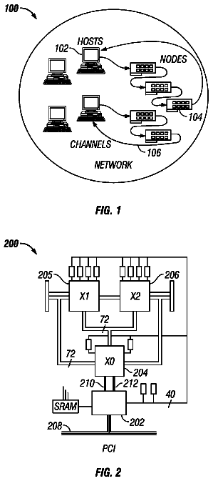
FIG. 1 is a block diagram illustrating an example network environment in which an embodiment of the present invention may be implemented;
FIG. 2 is a block diagram illustrating an example architecture of an appliance that performs integrated caching in accordance with an embodiment of the present invention;
FIG. 3A is a flow diagram of steps taken in an embodiment of a method of the present invention for integrating device operations with packet processing and the packet processing timer;
FIG. 3B is a flow diagram of steps taken in an embodiment of a method of the present invention for practicing invalidation granularity techniques in view of FIG. 3A;
FIG. 4A is a flow diagram of steps taken in an embodiment of a method of the present invention using invalidation commands to invalidate stale objects;
FIG. 4B is a flow diagram of steps taken in an embodiment of a method of the present invention incorporating invalidation of groups of objects;
FIG. 4C is a flow diagram of steps taken in an embodiment of a method of the present invention wherein a client request is parsed for object determinants;
FIG. 4D is a flow diagram of steps taken in an embodiment of a method of the present invention incorporating invalidation of groups of objects using object determinants;
FIG. 5. is a flow diagram of steps taken in an embodiment of a method of the present invention for providing a flash cache technique;
FIG. 6. is a flow diagram of steps taken in an embodiment of a method of the present invention for providing a flash crowd control technique;
FIGS. 7A and 7B are flow diagrams of steps taken in an embodiment of a method of the present invention for providing entity tag and cache control for an object; and
FIGS. 8A and 8B are block diagrams of embodiments of a computing device for practicing an illustrative embodiment of the present invention.
The features and advantages of the present invention will become more apparent from the detailed description set forth below when taken in conjunction with the drawings, in which like reference characters identify corresponding elements throughout. In the drawings, like reference numbers generally indicate identical, functionally similar, and/or structurally similar elements.
Detailed description
A. Example Network Environment
FIG. 1 illustrates an example network environment 100 in which an embodiment of the present invention may be practiced. As shown in FIG. 1, example network environment 100 includes a plurality of clients 102a-102n, a plurality of servers 106a-106n, and an appliance 104, which may also referred to as a cache appliance, device, or cache. The servers 106a-106n originate and manage databases, such as object or relational databases, that provide requested content to the clients 102a-102n. For this reason, the servers 106a-106n are sometimes referred to herein as "originating servers" because they typically, though not necessarily, originate the objects forming the requested content. Each of the clients 102a-102n and servers 106a-106n may be any type and form of computing device, such as the computing device 800 described in more detail later in conjunction with FIGS. 8A and 8B. For example, any of the client 102a-102n may be a mobile computing device, such as a telecommunication device, e.g., cellphone or personal digital assistant, or a laptop or notebook computer in addition to any type of desktop computer.
Each of the clients 102a-102n are communicatively coupled to appliance 104 via a public data communication network 108, while appliance 104 is communicatively coupled to servers 106a-106n via a private data communication network 110. In one embodiment, public data communication network 108 comprises the Internet and private data communication network 110 comprises an enterprise network. The public data communication network 108 and private data communication network 110 can be any type and form of network, public, private or otherwise, and in some cases, may be the same network.
Although FIG. 1 shows a network 108 and a network 1110 between the clients 102a-102n and the servers 106a-106n, the clients 102a-102n and the servers 106a-106n may be on the same network 108 or 110. The networks 108 and 110 can be the same type of network or different types of networks. The network 108 and/or the network 110 can be a local-area network (LAN), such as a company Intranet, a metropolitan area network (MAN), or a wide area network (WAN), such as the Internet or the World Wide Web. The network 108 and/or 110 may be any type and/or form of network and may include any of the following: a point to point network, a broadcast network, a wide area network, a local area network, a telecommunications network, a data communication network, a computer network, an ATM (Asynchronous Transfer Mode) network, a SONET (Synchronous Optical Network) network, a SDH (Synchronous Digital Hierarchy) network, a wireless network and a wireline network. The topology of the network 108 and/or 110 may be a bus, star, or ring network topology. The network 108 and/or 110 and network topology may be of any such network or network topology as known to those ordinarily skilled in the art capable of supporting the operations of the present invention described herein.
As shown in FIG. 1, the appliance 104 is shown between the public data communication network 108 and the private data communication network 110 some In other embodiments, the appliance 104 may be located on the public data communication network 108, or on the private data communication network 110. In other embodiments, the appliance 104 could be an integral part of any individual client 102a-102n or any individual server 106a-106n on the same or different network 108, 110 as the client 102a-102n. As such, the appliance 104 may be located at any point in the network or network communications path between a client 102a-102n and a server 106a-106n.
In accordance with an embodiment of the present invention, the appliance 104 includes cache management logic and also includes or has access to a storage medium which it utilizes to implement a cache memory. Using these features, appliance 104 monitors object requests made by clients 102a-102n to any of the servers 106a-106n. Objects returned from servers 106a-106n in response to these object requests are stored in the cache memory by appliance 104. Subsequent requests for the same object from any of clients 102a-102n are intercepted by appliance 104, which attempts to deliver the object from the cache rather than passing the request on to servers 106a-106n. This provides the dual benefit of reducing both the time required to respond to requests from clients 102a-102n and the load on the infrastructure supporting servers 106a-106n.
In summary, the network environment 100 depicted in FIG. 1 is presented by way of example only and is not intended to be limiting. Based on the teachings provided herein, persons skilled in the relevant art(s) will readily appreciate that the present invention may be implemented in any network environment in which object requests and responses are transferred between nodes of one or more network(s).
B. Example Appliance or Device Architecture
As will be described in more detail herein, in an embodiment of the present invention, the appliance 104 integrates caching functionality at the kernel level of the operating system with one or more other processing tasks, including but not limited to decryption, decompression, or authentication and/or authorization. Such an implementation is illustrated in the commonly owned and co-pending U.S. patent application Ser. No. 11/169,002 entitled "Method and Device for Performing Integrated Caching in a Data Communications Network," filed Jun. 29, 2005, which is incorporated by reference herein. Such an example architecture is described herein in accordance with FIG. 2, but the present invention is not so limited and other architectures may be used in practicing the operations of the present invention described herein.
FIG. 2 illustrates an example architecture 200 of an appliance 104. As noted above, architecture 200 is provided by way of illustration only and is not intended to be limiting. As shown in FIG. 2, example architecture 200 consists of a hardware layer 206 and a software layer divided into a user space 202 and a kernel space 204.
Hardware layer 206 provides the hardware elements upon which programs and services within kernel space 204 and user space 202 are executed. Hardware layer 206 also provides the structures and elements which allow programs and services within kernel space 204 and user space 202 to communicate data both internally and externally with respect to appliance 104. As shown in FIG. 2, the hardware layer 206 includes a processing unit 262 for executing software programs and services, a memory 264 for storing software and data, network ports 266 for transmitting and receiving data over a network, and an encryption processor 260 for performing functions related to Secure Sockets Layer processing of data transmitted and received over the network. In some embodiments, the central processing unit 262 may perform the functions of the encryption processor 260 in a single processor. Additionally, the hardware layer 206 may comprise multiple processors for each of the processing unit 262 and the encryption processor 260. Although the hardware layer 206 of appliance 104 is generally illustrated with an encryption processor 260, processor 260 may be a processor for performing functions related to any encryption protocol, such as the Secure Socket Layer (SSL) or Transport Layer Security (TLS) protocol. In some embodiments, the processor 260 may be a general purpose processor (GPP), and in further embodiments, may be have executable instructions for performing processing of any security related protocol.
Although the hardware layer 206 of appliance 104 is illustrated with certain elements in FIG. 2, the hardware portions or components of appliance 104 may comprise any type and form of elements, hardware or software, of a computing device, such as the computing device 800 illustrated and discussed in conjunction with FIGS. 8A and 8B further herein. In some embodiments, the appliance 104 may comprise a server, gateway, router, switch, bridge or other type of computing or network device, and have any hardware and/or software elements associated therewith.
The operating system of appliance 104 allocates, manages, or otherwise segregates the available system memory into kernel space 204 and user space 204. In example software architecture 200, the operating system may be any type and/or form of Unix operating system although the invention is not so limited. As such, the appliance 104 can be running any operating system such as any of the versions of the Microsoft.RTM. Windows operating systems, the different releases of the Unix and Linux operating systems, any version of the Mac OS.RTM. for Macintosh computers, any embedded operating system, any network operating system, any real-time operating system, any open source operating system, any proprietary operating system, any operating systems for mobile computing devices or network devices, or any other operating system capable of running on the appliance 104 and performing the operations described herein.
The kernel space 204 is reserved for running the kernel 230, including any device drivers, kernel extensions or other kernel related software. As known to those skilled in the art, the kernel 230 is the core of the operating system, and provides access, control, and management of resources and hardware-related elements of the application 104. In accordance with an embodiment of the present invention, the kernel space 204 also includes a number of network services or processes working in conjunction with a cache manager 232. sometimes also referred to as the integrated cache, the benefits of which are described in detail further herein. Additionally, the embodiment of the kernel 230 will depend on the embodiment of the operating system installed, configured, or otherwise used by the device 104.
In one embodiment, the device 104 comprises one network stack 267, such as a TCP/IP based stack, for communicating with the client 102a-102b and/or the server 106a-106n. In one embodiment, the network stack 267 is used to communicate with a first network, such as network 108, and a second network 110. In some embodiments, the device 104 terminates a first transport layer connection, such as a TCP connection of a client 102a-102n, and establishes a second transport layer connection to a server 106a-106n for use by the client 102a-102n, e.g., the second transport layer connection is terminated at the appliance 104 and the server 106a-106n. The first and second transport layer connections may be established via a single network stack 267. In other embodiments, the device 104 may comprise multiple network stacks, for example 267 and 267', and the first transport layer connection may be established or terminated at one network stack 267, and the second transport layer connection on the second network stack 267'. For example, one network stack may be for receiving and transmitting network packet on a first network, and another network stack for receiving and transmitting network packets on a second network. In one embodiment, the network stack 267 comprises a buffer 243 for queuing one or more network packets for transmission by the appliance 104.
As shown in FIG. 2, the kernel space 204 includes the cache manager 232, a high-speed layer 2-7 integrated packet engine 240, an encryption engine 234, a policy engine 236 and multi-protocol compression logic 238. Running these components or processes 232, 240, 234, 236 and 238 in kernel space 204 or kernel mode instead of the user space 202 improves the performance of each of these components, alone and in combination. Kernel operation means that these components or processes 232, 240, 234, 236 and 238 run in the core address space of the operating system of the device 104. For example, running the encryption engine 234 in kernel mode improves encryption performance by moving encryption and decryption operations to the kernel, thereby reducing the number of transitions between the memory space or a kernel thread in kernel mode and the memory space or a thread in user mode. For example, data obtained in kernel mode may not need to be passed or copied to a process or thread running in user mode, such as from a kernel level data structure to a user level data structure. In another aspect, the number of context switches between kernel mode and user mode are also reduced. Additionally, synchronization of and communications between any of the components or processes 232, 240, 235, 236 and 238 can be performed more efficiently in the kernel space 204.
In some embodiments, any portion of the components 232, 240, 234, 236 and 238 may run or operate in the kernel space 204, while other portions of these components 232, 240, 234, 236 and 238 may run or operate in user space 202. In one embodiment, the present invention uses a kernel-level data structure providing access to any portion of one or more network packets, for example, a network packet comprising a request from a client 102a-102n or a response from a server 106a-106n. In some embodiments, the kernel-level data structure may be obtained by the packet engine 240 via a transport layer driver interface or filter to the network stack 267. The kernel-level data structure may comprise any interface and/or data accessible via the kernel space 204 related to the network stack 267, network traffic or packets received or transmitted by the network stack 267. In other embodiments, the kernel-level data structure may be used by any of the components or processes 232, 240, 234, 236 and 238 to perform the desired operation of the component or process. In one embodiment, a component 232, 240, 234, 236 and 238 is running in kernel mode 204 when using the kernel-level data structure, while in another embodiment, the component 232, 240, 234, 236 and 238 is running in user mode when using the kernel-level data structure. In some embodiments, the kernel-level data structure may be copied or passed to a second kernel-level data structure, or any desired user-level data structure.
The cache manager 232 may comprise software, hardware or any combination of software and hardware to provide cache access, control and management of any type and form of content, such as objects or dynamically generated objects served by the originating servers 106a-106n. The data, objects or content processed and stored by the cache manager 232 may comprise data in any format, such as a markup language, or communicated via any protocol. In some embodiments, the cache manager 232 duplicates original data stored elsewhere or data previously computed, generated or transmitted, in which the original data may require longer access time to fetch, compute or otherwise obtain relative to reading a cache memory element. Once the data is stored in the cache memory element, future use can be made by accessing the cached copy rather than refetching or recomputing the original data, thereby reducing the access time. In some embodiments, the cache memory element nat comprise a data object in memory 264 of device 104. In other embodiments, the cache memory element may comprise memory having a faster access time than memory 264. In another embodiment, the cache memory element may comprise any type and form of storage element of the device 104, such as a portion of a hard disk. In some embodiments, the processing unit 262 may provide cache memory for use by the cache manager 232 of the present invention. In yet further embodiments, the cache manager 232 may use any portion and combination of memory, storage, or the processing unit for caching data, objects, and other content.
Furthermore, the cache manager 232 of the present invention includes any logic, functions, rules, or operations to perform any embodiments of the techniques of the present invention described herein. For example, the cache manager 232 includes logic or functionality to invalidate objects based on the expiration of an invalidation time period or upon receipt of an invalidation command from a client 102a-102n or server 106a-106n. In some embodiments, the cache manager 232 may operate as a program, service, process or task executing in the kernel space 204, and in other embodiments, in the user space 202. In one embodiment, a first portion of the cache manager 232 executes in the user space 202 while a second portion executes in the kernel space 204. In some embodiments, the cache manager 232 can comprise any type of general purpose processor (GPP), or any other type of integrated circuit, such as a Field Programmable Gate Array (FPGA), Programmable Logic Device (PLD), or Application Specific Integrated Circuit (ASIC).
The policy engine 236 may include, for example, an intelligent statistical engine or other programmable application(s). In one embodiment, the policy engine 236 provides a configuration mechanism to allow a user to identifying, specify, define or configure a caching policy. Policy engine 236, in some embodiments, also has access to memory to support data structures such as lookup tables or hash tables to enable user-selected caching policy decisions. In other embodiments, the policy engine 236 may comprise any logic, rules, functions or operations to determine and provide access, control and management of objects, data or content being cached by the appliance 104 in addition to access, control and management of security, network traffic, network access, compression or any other function or operation performed by the appliance 104. Further examples of specific caching policies are further described herein.
The encryption engine 234 comprises any logic, business rules, functions or operations for handling the processing of any security related protocol, such as SSL or TLS, or any function related thereto. For example, the encryption engine 234 encrypts and decrypts network packets, or any portion thereof, communicated via the appliance 104. The encryption engine 234 may also setup or establish SSL or TLS connections on behalf of the client 102a-102n, server 106a-106n, or appliance 104. As such, the encryption engine 234 provides offloading and acceleration of SSL processing. In one embodiment, the encryption engine 234 uses a tunneling protocol to provide a virtual private network between a client 102a-102n and a server 106a-106n. In some embodiments, the encryption engine 234 is in communication with the Encryption processor 260. In other embodiments, the encryption engine 234 comprises executable instructions running on the Encryption processor 260.
The multi-protocol compression engine 238 comprises any logic, business rules, function or operations for compressing one or more protocols of a network packet, such as any of the protocols used by the network stack 267 of the device 104. In one embodiment, multi-protocol compression engine 238 compresses bi-directionally between clients 102a-102n and servers 106a-106n any TCP/IP based protocol, including Messaging Application Programming Interface (MAPI) (email), File Transfer Protocol (FTP), HyperText Transfer Protocol (HTTP), Common Internet File System (CIFS) protocol (file transfer), Independent Computing Architecture (ICA) protocol, Remote Desktop Protocol (RDP), Wireless Application Protocol (WAP), Mobile IP protocol, and Voice Over IP (VoIP) protocol. In other embodiments, multi-protocol compression engine 238 provides compression of Hypertext Markup Language (HTML) based protocols and in some embodiments, provides compression of any markup languages, such as the Extensible Markup Language (XML). In one embodiment, the multi-protocol compression engine 238 provides compression of any high-performance protocol, such as any protocol designed for appliance 104 to appliance 104 communications. In another embodiment, the multi-protocol compression engine 238 compresses any payload of or any communication using a modified transport control protocol, such as Transaction TCP (T/TCP), TCP with selection acknowledgements (TCP-SACK), TCP with large windows (TCP-LW), a congestion prediction protocol such as the TCP-Vegas protocol, and a TCP spoofing protocol.
As such, the multi-protocol compression engine 238 of the present invention accelerates performance for users accessing applications via desktop clients, e.g., Microsoft Outlook and non-Web thin clients, such as any client launched by popular enterprise applications like Oracle, SAP and Siebel, and even mobile clients, such as the Pocket PC. In some embodiments, the multi-protocol compression engine 238 by executing in the kernel mode 204 and integrating with packet processing engine 240 accessing the network stack 267 is able to compress any of the protocols carried by the TCP/IP protocol, such as any application layer protocol.
The description continues in the full USPTO document.
 Lapsed, fee not paid5 drawings