Background
I. Field
The following description relates generally to wireless communication networks and more particularly to varied transmission time interval size for forward link and reverse link transmissions in multi-user wireless systems.
II. Background
Wireless networking systems are utilized by many to communicate wherever the user may be located at a particular time (e.g. home, office, traveling, . . . ). Wireless communication devices have become smaller and more powerful to meet user needs while improving portability and convenience. Users have found many uses for wireless communication devices including cellular telephones, personal digital assistants (PDAs) and the like.
A typical wireless communication network (e.g., employing frequency, time, and code division techniques) includes one or more base stations that provide a coverage area and one or more mobile (e.g., wireless) user devices that can transmit and receive data within the coverage area. A typical base station can simultaneously transmit multiple data streams for broadcast, multicast, and/or unicast services, wherein a data stream is a stream of data that can be of independent reception interest to a user device.
Various factors can affect the efficiency and performance of wireless communication. For example, the amount of traffic or data communication occurring in a coverage area can reduce data transmission times and produce interference. The data rate can also affect wireless communication and overall throughput may be limited by the link level transmission rate. In the case of a limited transmission rate, typical packet sizes are relatively small, needing modest decoding horsepower. The transmission time intervals that should be utilized for the packets can differ depending on communication parameters or factors. For example, some packets should utilize short transmission time interval while others should utilize a longer transmission time interval to improve the wireless communication.
Based on the aforementioned, techniques for providing short transmission time interval duration to access terminals with good channel conditions, for example, help achieve high peak throughputs. At substantially the same time, users having moderate to poor channel conditions, for example, can be provided with a long transmission time interval. In addition, flexible partitioning of bandwidth resources between short transmission time interval and long transmission time interval can benefit transmissions in multi-user wireless systems.
Summary
This summary is not an extensive overview of the one or more embodiments, and is intended to neither identify key or critical elements of the embodiments nor delineate the scope of such embodiments. Its sole purpose is to present some concepts of the described embodiments in a simplified form as a prelude to the more detailed description that is presented later. Accordingly, a method, an apparatus, a processor, and a computer program product for assigning transmission time intervals is described.
In order to assign transmission time intervals, a channel condition of a packet is measured by at least one wireless device. A data rate associated with the at least one wireless device may also be ascertained. Next, a determination may be made whether to schedule a long transmission time interval or a short transmission time interval to the packet based in part on the detected channel condition. The ascertained data rate may also be used to help determine the time interval. A long transmission time interval can be scheduled, for example, if the channel condition is poor and/or there is a low data rate. A short transmission time interval can be scheduled if, for example, the channel condition is good and/or the data rate is high or fast.
In addition, an interlacing structure is indicated from at least one of a plurality of interlacing structures for the packet. The interlace structure may determine a retransmission interval. The retransmission interval may be a hybrid automatic repeat request (HARQ) interval. The interlace interval can be indicated by way of issuing a channel assignment message. One way of indicating the interlace assignment is by adding an extra bit to a forward link assignment message (FLAM) or a reverse link assignment message (RLAM) to indicate the interlacing structure for the encoded packet. The channel assignment message may be transmitted on the forward-link prior to or at substantially the same time as a forward-link packet transmission, or on the forward-link prior to a reverse-link packet transmission.
The interlacing structure for the encoded packet may be three if the channel condition is poor. The interlacing structure for the encoded packet may be six if the channel condition is good. The interlacing structure may also determine a forward link or reverse link packet transmission interval. The interlacing structure for the forward link and the reverse link interfaces may be the same. This would produce the same transmission and retransmission delays on each of the forward link and the reverse link interface.
To the accomplishment of the foregoing and related ends, one or more embodiments comprise the features hereinafter fully described and particularly pointed out in the claims. The following description and the annexed drawings set forth in detail certain illustrative aspects of the one or more embodiments. These aspects are indicative, however, of but a few of the various ways in which the principles of various embodiments may be employed and the described embodiments are intended to include all such aspects and their equivalents.
Brief description of the drawings
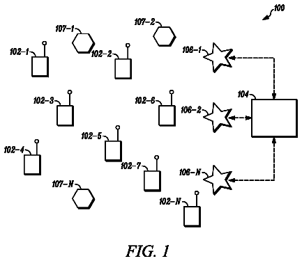
FIG. 1 illustrates a wireless communication system in accordance with various embodiments presented herein.
FIG. 2 illustrates a multiple access wireless communication system according to one or more embodiments.
FIG. 3 illustrates a system for a varied transmission time interval size for forward link and reverse link transmissions in multi-user wireless systems.
FIG. 4 illustrates a system for a varied transmission time interval size utilizing a channel condition and other communication parameters.
FIG. 5 illustrates flow chart of a methodology for assigning different users to different transmission time intervals.
FIG. 6 illustrates a short transmission time interval having six interlaces.
FIG. 7 illustrates a long transmission time interval having three interlaces.
FIG. 8 illustrates flexible partitions of resources with mixed interlaces.
FIG. 9 illustrates an H-ARQ transmission timing.
FIG. 10 illustrates an H-ARQ interlace structure for extended transmission duration assignments
FIG. 11 illustrates a flow chart of a methodology for transmitting a forward-link data packet.
FIG. 12 is a flow chart of a methodology for transmitting a reverse-link data packet.
FIG. 13 illustrates a wireless communication environment that can be employed in conjunction with the various systems and methods described herein.
Detailed description
Various embodiments are now described with reference to the drawings. In the following description, for purposes of explanation, numerous specific details are set forth in order to provide a thorough understanding of one or more aspects. It may be evident, however, that such embodiment(s) may be practiced without these specific details. In other instances, well-known structures and devices are shown in block diagram form in order to facilitate describing these embodiments.
As used in this application, the terms "component," "system," and the like are intended to refer to a computer-related entity, either hardware, firmware, a combination of hardware and software, software, or software in execution. For example, a component may be, but is not limited to being, a process running on a processor, a processor, an object, an executable, a thread of execution, a program, and/or a computer. By way of illustration, both an application running on a computing device and the computing device can be a component. One or more components can reside within a process and/or thread of execution and a component may be localized on one computer and/or distributed between two or more computers. In addition, these components can execute from various computer readable media having various data structures stored thereon. The components may communicate by way of local and/or remote processes such as in accordance with a signal having one or more data packets (e.g. data from one component interacting with another component in a local system, distributed system, and/or across a network such as the Internet with other systems by way of the signal).
Referring now to the drawings, FIG. 1 illustrates a wireless communication system 100 in accordance with various embodiments presented herein. System 100 can comprise one or more access point(s) 102 that receive, transmit, repeat, etc., wireless communication signals to each other and/or to one or more mobile devices 104. Access point(s) 102 can represent an interface between wireless system 100 and a wired network (not shown).
Each access point 102 can comprise a transmitter chain and a receiver chain, each of which can in turn comprise a plurality of components associated with signal transmission and reception (e.g., processors, modulators, multiplexers, demodulators, demultiplexers, antennas, . . . ). Mobile devices 104 can be, for example, cellular phones, smart phones, laptops, handheld communication devices, handheld computing devices, satellite radios, global positioning systems, PDAs, and/or other suitable devices for communicating over wireless system 100. In wireless system 100, the periodic transmission of small data packets (commonly referred to as beacons) from access point 102 can make known the presence of wireless system 100 and transmit system 100 information. Mobile devices 104 can sense the beacons and attempt to establish a wireless connection to access points 102 and/or to other mobile devices 104.
System 100 facilitates scheduling varied transmission time intervals (TTIs) to one or more users using mobile device(s) 104 to accommodate the communication channels and network conditions. System 100 can automatically detect, receive, and/or infer a channel condition, bandwidth, data rate, and/or various other communication parameters to determine whether a long TTI or a short TTI is best for the data transmission.
A component located in mobile device 104 can operate in conjunction with one or more access point 102 to facilitate monitoring the capabilities of the mobile device 104, such as the device's 104 decoding capabilities. Alternatively or in addition, the access point 102 can detect this information and schedule the respective data packets to an optimal TTI duration taking into account the various communication parameters, including the amount of traffic in the network.
FIG. 2 is an illustration of a multiple access wireless communication system according to one or more embodiments. Illustrated is a system 200 that can include a wireless local area network associated with a wired local area network (LAN). Access point 102 can be in communication with mobile devices 104. Access point 102 is connected to an Ethernet hub or switch 202 for a LAN. Ethernet hub 202 may be connected to one or more electronic devices 204 that can include personal computers, peripheral devices (e.g., facsimile machines, copiers, printers, scanners, etc.), servers, and the like. Ethernet hub 202 can be connected to a router 206 that transmits data packets to a modem 208. Modem 208 can transmit data packets to a wide area network (WAN) 210, such as the Internet. System 200 illustrates a single, simple network configuration. Many additional configurations of system 200 including alternative electronic devices are possible. Although system 200 has been illustrated and describe with reference to a LAN, it is possible that system 200 can utilize other technologies including Wireless Wide Area Network (WWAN) and/or Wireless Personal Area Network (WPAN) either separately or concurrently.
System 200 can facilitate scheduling different users to different TTI durations. By way of example and not limitation, if a channel is causing traffic or is slowly changing, it can benefit from a longer TTI for channel estimation. Thus, it can hold a certain amount of energy for channel estimation that provides a particular accuracy. The tradeoff between a short TTI and a long TTI is that with a short TTI some performance is lost, however, it allows a better processing time.
FIG. 3 illustrates a system 300 for a varied TTI size or duration for forward link and reverse link transmissions in multi-user wireless systems. System 300 includes an access point 302 and an access terminal 304. It should be understood that system 300 can include more than one access point 302 and/or more than one access terminal 304, however, only one of each is illustrated for ease of explanation.
Access point 302 can include an encoder 306, an optimizer 308, and a scheduler 310. These can be functional blocks that represent functions implemented by a processor, software or combination thereof (e.g. firmware). Encoder 306 is configured to encode signals and/or data packets for transmission to access terminal 304. In other embodiments, the optimizer 308 and/or scheduler 310 are associated with access terminal 304 and access terminal 304 performs the functionalities described below.
Optimizer 308 can be configured to optimize a communication between access point 302 and access terminal 304 and/or between two or more access terminals. Optimizer 308 can utilize information regarding a channel condition, bandwidth, packet size, data rate, and other parameters to optimize the communication. This information can be communicated to scheduler 310. Optimizer 308 can further support at least two different interlacing structures or two different kinds of assignments.
Scheduler 310 can be configured to schedule an access terminal (or user thereof) to a particular bandwidth and or TTI. A packet size or the number of bits that can be transmitted together depends on the TTI since a longer TTI allows more bits to be sent together. Scheduler 310 can utilize the information received from optimizer 308 and/or from the access terminal 302 to make a determination as to the TTI size. For example, access terminal 304 can notify access point 302 and/or scheduler 310 to change the scheduling from a short TTI to a long TTI or vice versa. Access terminal 304 can make such a request if it is not getting the entire data packet, has problems with the communication, if there is a large data packet being received and/or sent, is receiving the communication at a high rate, etc.
Generally, a short TTI duration can be beneficial for access terminal(s) with good channel conditions since short TTI is instrumental to achieve high pick throughputs. Alternatively, long TTI is can be utilized for users in moderate to poor channel conditions. In a system where both types of users are dynamically supported, flexible partitioning of bandwidth resources between short and long TTI, or an alternative interlacing structure can be provided.
Access terminal 304 can include a decoder 312 and an acknowledger 314. Decoder 312 can decode a received signal and/or data packets therein for processing. Acknowledger 314 can employ an acknowledgment technique in conjunction with an ACK/NACK protocol. In other embodiments, access terminal 304 can include memory (not shown) and a processor (not shown) to allow access terminal 304 to process and/or store information.
Access terminal 304 can report its capabilities, including decoder size and what it can handle in terms of decoding. This information can be transmitted to access point 302, for example, when access terminal 304 connects to system 300 and periodically or continuously while access terminal 304 is associated with system 300. With this information, access point 302 can ascertain whether access terminal 304 is a strong or weak access terminal. For example, access point 302 may schedule access terminal 304 a large bandwidth in a large channel packet. If a channel causes traffic or is slowly changing, it can benefit from a larger TTI for channel estimation because it can hold a certain amount of energy for channel estimation. A shorter TTI allows a better processing time. Thus, for different types of communication (e.g. voice, data, image, video, . . . ), access point 302 may schedule a larger TTI or a shorter TTI depending on the best optimization for that particular channel and communication.
FIG. 4 illustrates a system 400 for a varied transmission time interval size utilizing a channel condition and other communication parameters. System 400 includes an access point 402 in wireless communication with an access terminal 404. Access point 402 can include an optimizer 406 and a scheduler 408. Access terminal 404 can include a decoder 410 that can decode a received signal and/or data packets therein for processing. Access terminal 404 can also include an acknowledger 412 that can employ an acknowledgment technique in conjunction with an ACK/NACK protocol. It should be understood that these can be functional blocks that represent functions implemented by a processor, software or combination thereof (e.g., firmware).
It should be understood that while the following is discussed with reference to access point 402, in other embodiments the functionalities can be performed by access terminal 404 and communicated to access point 402. Optimizer 406 can include a channel condition module 414 and a data rate module 416. Channel condition module 414 can be configured to analyze the condition of a channel. The channel condition can include parameters, such as the amount of network traffic, the amount of data sent/received within the network, etc. Data rate module 416 can be configured to determine a data rate of a current communication and/or an optimal data rate for a particular communication.
Scheduler 408 can include a bandwidth module 418 and a time transmission interval (TTI) module 420. The bandwidth module 418 is configured to determine a bandwidth for a communication. For example, if there are a number of users that operate on long TTI and others on short TTI, it might be desirable to give all the bandwidth to one user. For example, bandwidth module 418 can wait until the other users terminate because they follow different time lines. As the users terminate, it frees up the bandwidth.
The TTI module 420 is configured to schedule a particular communication to a short TTI or a long TTI. The TTI should be as long as possible in order to benefit from channel estimation. This is useful in systems, such as block-hopping systems where the user receives resources in units of blocks.
In some retransmission embodiments, scheduler 408 can add an extra bit to the Forward Link Assignment Message (FLAM) or Reverse Link Assignment Message (RLAM), indicating the interlacing structure for the particular packet. Link Assignment Messages (LAMs) can notify devices of a modification in resources: hop ports changes, packet formats, and so forth. In this embodiment the LAM would index the same set of hop-ports but now applies to a larger set of physical frames. The scheduler 408 additionally would make sure this LAM does not collide with other LAMs that is may have sent out earlier, especially if those other LAMs have different interlacing structure(s). The extra bit in the FLAM or RLAM, for example, could indicate as follows: if a "1," could indicate an interlacing structure wherein the HARQ interlace is six
and the PHY data interlace is three (3). If a "0," could indicate an interlacing structure wherein the HARQ interlace is eight
and the PHY data interlace is three (3). These are examples of an extra bit indicating an interlace structure. Many possible types and/or combinations of interlace structures can be indicated with the extra bit.
FIG. 5 illustrates flow chart of a methodology 500 for assigning different users to different transmission time intervals. The method 500 begins, at 502, where a channel condition of a packet communicated by at least one wireless device is detected and measured. The channel condition can be poor or good depending on various criteria including traffic in the wireless network. At 504, a data rate associated with the channel is ascertained. The data rate can be a factor of the amount of bits or data to be communicated. The method continues, at 506 where a determination is made whether to schedule a long transmission time interval or a short transmission time interval to the packet based in part on the detected channel condition and the ascertained data rate. A long transmission time interval can be scheduled if the channel condition is poor and/or if the data rate is low. A short transmission time interval can be scheduled if the channel condition is good and/or the data rate is high. It should be understood that more than one wireless device packet can be analyzes and assigned a transmission time interval according to the methodology 500. For example, multiple packets can be analyzes and can be included in an alternative interlacing structure, which will be discussed more below.
In some embodiments, a channel assignment message is issued, at 508. It should be understood that the channel assignment is optional. This channel assignment message can provide information regarding the desired interlacing structure for a particular packet. According to some embodiments, an extra bit can be added to the FLAM or RLAM to indicate such a structure. For forward-link transmissions, channel assignment can be issued and transmitted on the forward-link before or at substantially the same time as the forward-link packet transmission. For reverse link transmissions, channel assignment can be issued and transmitted on the forward-link before the reverse-link packet transmission. To avoid conflicts between the different types of assignments, the entire bandwidth can be divided into two parts, one for each type of assignments, for example.
FIG. 6 illustrates a short transmission time interval having six interlaces. Specifically, illustrated is a six interlace forward-link and reverse-link structure with the same transmission and retransmission delay on each interface. A multiple-access system can concurrently communicate with multiple terminals on the forward and reverse links. The forward link (or downlink) refers to the communication from the base station or access points to the terminals. The reverse link (or uplink) refers to the communication link from the terminals to the base stations or access points. The packet transmission and processing timeline for a single forward-link/reverse-link interface will now be described.
The structure for the access point is illustrated at the top of the figure at 602 having a six interlace forward-link and reverse-link structure, labeled as 1, 2, 3, 4, 5, and 6. The structure for the access terminal is illustrated at the bottom of the figure at 604 having a six interlace forward-link and reverse-link structure, labeled as A, B, C, D, E, and F. It should be understood that while both access point 602 and access terminal 604 are illustrated having two packets of data with a six interlace forward-link and reverse-link structure, there can be more or less packets of data and/or there can be more or less interlaces associated with the structure.
On the forward-link, access point 602 transmits an encoded forward-link packet at 606. This represents the first short TTI having the duration illustrated at TTI 1. Access terminal 604 decodes the forward-link packet and encodes and transmits a reverse-link acknowledgment to acknowledge that the last forward-link transmission or hybrid automatic repeat request (H-ARQ) retransmission was successfully received. The acknowledgment can be an acknowledgment technique in conjunction with an ACK/NACK protocol. The decoding and transmission of the reverse-link acknowledgment occur during 608, which represents TTIs B, C and D. The reverse-link ACK is decoded during 614 and encoding of the following forward-link transmission or H-ARQ retransmission is performed by access point 602 during TTIs 5 and 6, represented at 610.
On the reverse-link, access terminal 604 transmits an encoded reverse-link packet during TTI A, represented at 612. The reverse-link pack is decoded and a forward-link acknowledgment is sent, at 614, during TTIs labeled 2, 3, and 4. The acknowledgment confirms that the latest reverse-link transmission or H-ARQ retransmission was successfully received. At 616, the forward-link ACK is decoded and the following RL-transmission or H-ARQ retransmission is encoded.
It should be appreciated that this can process can repeat itself, as illustrated. Each transmission cycle can be accompanied by an opportunity to transmit a channel assignment message. For forward-link transmission, the channel assignment can be issued by access point 602 and transmitted on the forward-link prior to, or at substantially the same time as the forward-link packet transmission. For reverse-link transmissions, channel assignment can be issued and transmitted on the forward-link prior to the reverse-link packet transmission in a system that includes a centralized (access point) reverse-link scheduler. This is typically the case in some orthogonal reverse-link access systems. It should be understood that access terminal initiated reverse-link assignment may be used in a contention based reverse-link access system, such as DS-CDMA.
With reference now to FIG. 7, illustrated is a long transmission time interval having three interlaces and in particular illustrated is a three interlace forward-link and reverse-link structure with the same transmission and retransmission delay on each interface. The three interlaces for access point 702 are labeled 1, 2, and 3, while the three interlaces for access terminal 704 are labeled A, B, and C. In this figure, the TTI duration, or the duration of the first transmission of a forward-link/reverse-link packet and the subsequent H-ARQ retransmission thereof, is twice as large as the TTI duration in FIG. 6 discussed above.
On the forward-link access point 702 transmits an encoded forward-link packet at 706 during the first TTI. Access terminal 704 decodes the forward-link packet and further encodes and transmits a reverse-link acknowledgement during 708. The acknowledger is utilized to communicate successful receipt of the last forward-link transmission or H-ARQ retransmission. The acknowledgment can be an acknowledgment technique in conjunction with an ACK/NACK protocol. A system utilizing the longer TTI, as illustrated, transmits the ACK over two physical (PHY) frames, which can save on the instantaneous power requirement for the ACK. At 710, the reverse-link ACK is decoded and encoding of the following forward-link transmission or H-ARQ retransmission is performed. In some embodiments, during the forward-link transmission, channel assignment can be issued by the access point 702 and transmitted on the forward-link either before or at substantially the same time as the forward-link packet transmission.
On the reverse-link, an encoded reverse-link packet is transmitted by access terminal 704 during 712 or TTI "A". At 714, the reverse-link packet is decoded and a forward-link acknowledgment is sent confirming successful receipt of the latest reverse-link transmission or H-ARQ retransmission. During 716; the forward-link ACK is decoded and the following RL-transmission or H-ARQ retransmission is encoded. In some embodiments, during the reverse-link transmission, channel assignment can be issued by access point 702. The assignment can be transmitted on the forward-link before the reverse-link packet transmission in systems, for example, with a centralized reverse-link scheduler. Typically this is the situation in most orthogonal reverse-link access systems. Reverse-link assignment can be used in a contention based reverse-link access systems, such as DS-CDMA.
FIGS. 6 and 7 illustrate the situation when a user receives forward-link and transmits reverse-link transmissions on a single interlace. In general, access terminal can be scheduled multiple packets on multiple interlaces. The multiple packets can correspond to different H-ARQ processes. In addition, the forward-link and reverse-link interlaces assigned to the same access terminal do not have to be aligned in time.
FIG. 8 illustrates flexible partitions of resources with mixed interlaces or an alternative interlacing structure. The time interval for access point 802 is shown at the top and the time interval for access terminal 804 is shown at the bottom of the figure. Users of short TTIs are represented as A and B, while users of long TTI's are represented as C, D, E, and F. The long TTI is approximately twice as long as the short TTI and an ACK is transmitted over two PHY frames. The alternative interlacing structure can support link budget constrained users. To avoid conflicts in this alternative interlacing structure and the two different kinds of assignments, the entire bandwidth can be divided into two parts. Each part can be dedicated for each type of assignment. It should be understood that the described way of avoiding conflicts is for example purposes only and other means to avoid conflicts between the types of assignments can be utilized.
In some embodiments, a retransmission structure (which can be a two interlace structure) can be supported by adding an extra bit to the FLAM or RLAM that indicates the desired interlacing structure for a particular packet. The LAM can index the same set of hop-ports and can also apply to a larger set of physical frames. A scheduler can ensure that the LAM does not collide with LAMs sent out earlier, especially LAMs with a different interlacing structure. This can be accomplished, for example by reserving a set of channel tree nodes for use with the alternative interlacing structure.
A CDM control channel can puncture some of the tones assigned to a channel with the alternative interlacing structure. In a regular six interlace structure, for example, the CDM control channel punctures an entire channel, which is not assigned.
In order to fully appreciate the subject disclosure, short TTI will now be compared to the long TTI option. This comparison makes the assumption that there is a fixed retransmission time in both cases. With a short TTI duration, it is possible to achieve relatively short air interface latency. The reduction in latency is particularly significant when a scheduler (e.g., scheduler 310 or 408) targets to complete packet transmission in one TTI so that no H-ARQ retransmission is necessary most of the time.
With a short TTI duration, duty cycle of traffic transmission is small relative to a long TTI duration. This means that the required data processing (decoding, scheduling and encoding) rate per interlace is lower compared to the long TTI duration. For the same spectral efficiency and assignment size, a short TTI duration yields a smaller packet size (the number of information bits) compared to the long TTI duration, assuming the same spectral efficiency and the minimum number of H-ARQ transmissions need to decode a packet for both options.
A short TTI duration can lead to a larger number of interlaces compared to a long TTI duration. Each interlace can be accompanied with the corresponding forward-link/reverse-link control such as opportunity for forward-link/reverse-link channel assignments and forward-link/reverse-link ACK. Hence, the number of forward-link/reverse-link control segments will be larger for a short TTI option. Additionally, timing of these control channelsis tied to the timing of the respective interlace therefore reducing the benefit of statistical multiplexing and/or joint encoding of these control channels. In some cases, there is a limit to the achievable minimum control overhead as well as the granularity of resource partitioning between control and traffic. These factors imply a higher control overhead for the option with a short TTI duration.
Block hopping mode is commonly used for the RL traffic in orthogonal systems (such as OFDMA & LFDMA) and may be beneficial on the FL as well (e.g., OFDMA TDD). A single TTI may include one or more consecutive (TDM) blocks. In a block-hopping mode, channel and interference estimation can be done locally in every block, based on dedicated pilots (e.g., placed within this block). For slowly varying (pedestrian) access terminals, channel estimation performance depends on the number of pilot clusters across the frequency band spanned by the block as well as the total pilot energy. Hence, a longer TTI duration helps to reduce pilot overhead without performance loss. Consequently, a long TTI duration leads to a better link efficiency for slowly varying channels. It is worth mentioning that there is no fundamental link performance penalty for fast varying channels when a long TTI duration is chosen.
High data rate access terminals with good channel conditions tend to receive large channel assignments (in terms of the number of tones per interlace), to take advantage of high spectral efficiency, and can achieve a high data rate. For access terminals with very high rates at the link level, the overall throughput may be limited by the air interface turnaround time. Therefore, low air interface latency is important, calling for a short TTI duration, large assignment size and high spectral efficiency to reduce pick load of TX/RX data processing such as decoding. A large assignment per access terminal indicates a relatively low control overhead (since the assignment and ACK overhead do not scale along with the assignment size). Finally, channel estimation accuracy improves at high signal-to-noise ratios (SNRs), hence link performance penalty of a short TTI duration is not that critical. Overall, a short TTI option can be suitable for high data rate access terminals in good channel conditions.
For access terminals with low data rates and moderate to poor channel condition, the overall throughput is can be limited by the link level transmission rate, hence stringent latency requirements do not apply. Due to the limited transmission rate, typical packet sizes are relatively small resulting in modest requirements on the decoding horsepower. Consequently, a somewhat bursty processing can be tolerated. Overall, the key benefits of a short TTI duration are not very important for the access terminals with moderate channel quality. However, a short TTI duration can lead to a very small packet sizes for access terminals in poor channel conditions, given that link budget per interlace reduces along with the TTI duration. A small packet size (on the order of about 100 bits and less) entails substantial losses in coding gain, hence further hurting access terminals in poor channel conditions. From the point of view of link efficiency, it is beneficial to FDM users in poor channel conditions. Hence, multiple users can be scheduled over the same interlace thereby increasing control overhead per interlace. In this context, reducing the number of interlaces (related to the increase in TTI duration) helps to reduce control overhead. Finally, access terminals in poor channel conditions can benefit from a boost in link level performance that comes along with a long TTI duration.
FIG. 9 illustrates an H-ARQ transmission timing. Both forward and reverse link data transmissions support H-ARQ. To provide H-ARQ related processing time at the access point (AP) and access terminal (AT), a seven interlace structure can be utilized for the forward-link data packets and a nine interlace structure can be utilized for the reverse-link data packets. It is to be understood that more or fewer frames can be utilized and the interlace structure is for example purposes. Timing of transmissions associated with one of the seven interlaces is shown for forward-link data packets, at 902, and for reverse-link data packets, at 904. The timing of the other interlaces is the same but with all transmissions shifted by the same number of PHY frames. This interlace structure ignores the presence of the superframe preamble, that is the PHY frame level transmission timing occurs as if the superframe preamble were not present on forward-link and as if the first PHY frame were not lengthened on reverse-link.
For the forward link, assignments that arrive in forward-link PHY frame k apply to the interlace containing forward-link PHY frame k, and a forward-link transmission on forward-link PHY frame k is acknowledged on reverse-link PHY frame k+3. HARQ retransmissions associated with the transmission that starts in PHY frame k occur in PHY frames k+6n where n is the retransmission index, n=0, 1, . . . . This frame structure provides an H-ARQ retransmission latency of .about.5.5 ms with 1.8 ms (2 PHY frames) of processing time at both the AT and the AP.
For the reverse-link data packets, assignments that arrive in forward-link PHY frame k apply to the interlace containing reverse-link PHY frame k+2, and a reverse-link transmission on reverse-link PHY frame k is acknowledged on forward-link PHY frame k+6. H-ARQ retransmissions associated with a transmission that starts in PHY frame k occur in PHY frames k+8n where n is the retransmission index, n=0, 1, . . . .
This frame structure provides an H-ARQ retransmission latency of 5.5 ms with 0.9 ms (1 PHY frame) of processing time at the AT, and 2.7 ms (3 PHY frames) of processing time at the AP. The reduced processing time at the AT is appropriate for reverse-link since the AT only needs to perform assignment demodulation and data packet encoding/modulation--tasks that are much simpler than data packet demodulation.
With reference now to FIG. 10, illustrated is an H-ARQ interlace structure for extended transmission duration assignments. It should be understood that the examples disclosed herein are merely examples and there may be more or less frames than those shown and described in the figures. In addition to the H-ARQ interlace structure described above, an extended transmission duration assignment is provided. Such assignments can extend transmission over multiple PHY frames and can alter the timing of transmissions and corresponding ACK transmissions relative to the assignments illustrated in the above figures. The extended transmission duration assignments can be useful for link-budget limited users who can benefit from encoding transmissions over a longer transmission duration. Extended transmission duration assignments can create a potential for resource assignment collisions with standard assignments, and the access node (AN) should manage resource assignments to prevent such collisions.
For the forward-link data packets, illustrated at the top of figure, at 1002, extended transmission duration assignments that arrive in forward-link PHY frame k apply to the interlace containing forward-link PHY frames k through k+4. A forward-link transmission on forward-link PHY frames k through k+4 is acknowledged on reverse-link PHY frame k+8 through k+9. H-ARQ retransmissions associated with the transmission that starts in PHY frame k start in PHY frames k+12n where n is the retransmission index, n=0, 1, . . . . Frame structure 1002 provides an H-ARQ retransmission latency of 11 ms with 1.8 ms (2PHY frames) of processing time at both the access terminal (AT) and the access node.
The description continues in the full USPTO document.
 Lapsed, fee not paid7 drawings