Incorporation by reference
The disclosure of Japanese Patent Application No. 2009-237764 filed on Oct. 14, 2009 including the specification, drawings and abstract is incorporated herein by reference in its entirety.
Background of the invention
1. Field of the invention
The invention relates to a control apparatus for a vehicular power transmitting apparatus, and more particularly, to failure detection in that vehicular power transmitting apparatus.
2. Description of the related art
Clutches and brakes provided in a vehicular power transmitting apparatus are formed of hydraulic actuators driven by hydraulic pressure, and are controlled appropriately by a hydraulic control circuit. In this hydraulic control circuit there are a plurality of individual linear solenoid valves that are able to be electrically controlled. The apply force of the clutches and brakes is optimally controlled based on control pressure output from these linear solenoid valves. Incidentally, the unit price of such linear solenoid valves is relatively high, so reducing the number of these valves by even one is desirable in view of manufacturing costs. With respect to this, Japanese Patent No. 4069054 describes a hydraulic control apparatus of a power transmitting apparatus in which lockup control of a lockup clutch and control of a forward-reverse switching apparatus are performed using a single linear solenoid valve. Such a structure reduces the number of linear solenoid valves, and thus enables manufacturing costs to be kept down.
Incidentally, Japanese Patent No. 4069054 makes no mention of detecting a failure when some sort of abnormality occurs with the structure that performs both lockup control and clutch control with a single linear solenoid valve described in Japanese Patent No. 4069054. Therefore, with the structure described in Japanese Patent No. 4069054, an oil pressure switch and a hydraulic sensor for detecting a failure of the linear solenoid valve are necessary, and as a result, the hydraulic control circuit becomes complex. In addition, a system is necessary for successively detecting failures in the oil pressure switch and hydraulic sensor themselves, which ends up increasing development man-hours.
Summary of invention
The invention therefore provides a control apparatus for a vehicular power transmitting apparatus capable of detecting a failure without providing failure detecting means, such as an oil pressure switch, in a control apparatus for a vehicular power transmitting apparatus capable of performing clutch control and lockup control with a single linear solenoid valve.
A first aspect of the invention relates to a control apparatus for a vehicular power transmitting apparatus that includes a first valve that controls the supply of hydraulic fluid to a running clutch in connection with the switching of the operating state of a first solenoid valve; a second valve that controls the supply of hydraulic fluid to a lockup clutch in connection with the switching of the operating state of a second solenoid valve; and a linear solenoid valve that selectively controls the apply force of the running clutch and the lockup clutch according to the supply of control pressure to the first valve and the second valve. The control apparatus detects a failure state of a part related to the operation of the power transmitting apparatus by the operating state of the running clutch and the operating state of the lockup clutch.
With the control apparatus for a vehicular power transmitting apparatus according to the aspect described above, the failure state of a part is detected based on the operating state of the running clutch and the operating state of the lockup clutch. Therefore, the failure state of a part can be detected without providing a hydraulic sensor and an oil pressure switch or the like for detecting a failure. That is, failure detecting performance can be ensured without increasing the number of parts and making the structure more complex.
Brief description of drawings
The foregoing and/or further objects, features and advantages of the invention will become more apparent from the following description of example embodiments with reference to the accompanying drawings, in which like numerals are used to represent like elements and wherein:
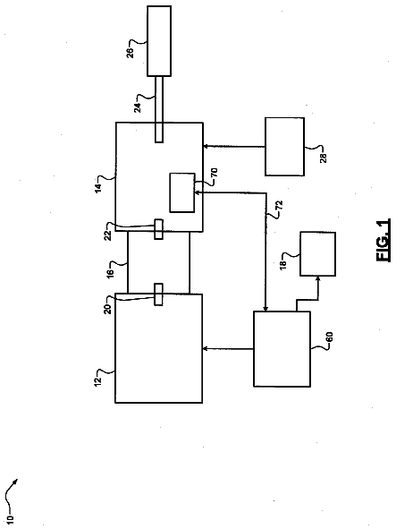
FIG. 1 is a skeleton view of the structure of a vehicular power transmitting apparatus according to an example embodiment of the invention;
FIG. 2 is a block line diagram of the main portions of a control system provided in a vehicle for controlling a vehicle drive system and the like shown in FIG. 1, according to the example embodiment of the invention;
FIG. 3 is a hydraulic circuit diagram showing the main portions related to lockup control of a lockup clutch and apply-pressure control of a forward clutch and a reverse brake according to an operation of a shift lever, in a hydraulic control circuit that controls the vehicular power transmitting apparatus shown in FIG. 1, according to the example embodiment of the invention;
FIG. 4 is a relationship diagram (i.e., a map or region line diagram) showing a release region (i.e., a lockup off region), a slip control region, and an apply region (i.e., a lockup on region) of a lockup clutch, with the throttle valve opening amount and the vehicle speed as variables, according to the example embodiment of the invention;
FIG. 5 is a functional block line diagram of the main control functions performed by an electronic control unit shown in FIG. 2, according to the example embodiment of the invention;
FIG. 6 is a time chart showing the state of the vehicle when the forward-reverse clutch is released during neutral control, according to the example embodiment of the invention;
FIG. 7 is a time chart showing the state of the vehicle when an on failure has occurred in a linear solenoid valve when releasing the lockup clutch, according to the example embodiment of the invention;
FIG. 8 is a flowchart illustrating the main parts of a control operation of the electronic control unit, according to the example embodiment of the invention;
FIG. 9 is a flowchart illustrating a control operation executed when lockup control of the lockup clutch is allowed in FIG. 8, according to the example embodiment of the invention;
FIG. 10 is a flowchart illustrating a control operation executed when neutral control is allowed in FIG. 8, according to the example embodiment of the invention;
FIG. 11 is a flowchart illustrating a control operation executed when neutral control is prohibited in FIG. 8, according to the example embodiment of the invention; and
FIG. 12 is another flowchart illustrating the main parts of a control operation of the electronic control unit, which corresponds to the flowchart in FIG. 8, according to the example embodiment of the invention.
Detailed description of embodiments
In an example embodiment of the invention, an on failure of the first solenoid valve, the second solenoid valve, and the linear solenoid valve corresponds to a failure in which hydraulic pressure is constantly output from each of those electromagnetic valves. Also, an off failure of the first solenoid valve, the second solenoid valve, and the linear solenoid valve corresponds to a failure in which hydraulic pressure is not output despite a command being output to output hydraulic pressure from each of those electromagnetic valves.
Also, in the example embodiments of the invention, the transmission corresponds to a belt-type continuously variable transmission. Therefore, the direction in which the vehicle travels can be appropriately switched by the running clutch.
Hereinafter, example embodiments of the invention will be described in detail with reference to the accompanying drawings. Incidentally, the drawings described in the example embodiments below have been simplified or modified as appropriate, so the scale ratios and the shapes and the like of the portions are not always accurately depicted.
FIG. 1 is a skeleton view of the structure of a vehicular power transmitting apparatus 10 to which the invention has been applied. This vehicular power transmitting apparatus 10 is a transverse mounted automatic transmission that is preferably used in a FF (front engine-front drive) vehicle, and includes an engine 12 as a driving source for running. The output of the engine 12 that is formed by an internal combust on engine is transmitted from a torque converter 14 that serves as a fluid power transmitting device to a differential gear unit 22 via a front-reverse switching apparatus 16, a belt-type continuously variable transmission (CVT) 18, and reduction gears 20, and then distributed to left and right driving wheels 24L and 24R.
The torque converter 14 includes a pump impeller 14p that is connected to a crankshaft of the engine 12, and a turbine runner 14t that is connected to the front-reverse switching apparatus 16 via a turbine shaft 34 that corresponds to an output side member of the torque converter 14, and transmits power via fluid. Also, a lockup clutch 26 is provided between the pump impeller 14p and the turbine runner 14t. This lockup clutch 26 is structured so as to be applied or released by the supply of hydraulic pressure with respect to an apply-side fluid chamber and a release-side fluid chamber being switched by a lockup control valve 106 and the like inside a hydraulic control circuit 100 (see FIG. 3). Completely applying the lockup clutch 26 causes the pump impeller 14p and the turbine runner 14t to rotate together as a single unit. Also, a mechanical oil pump 28 that generates hydraulic pressure for executing belt squeezing force control and shift control in the CVT 18 and apply and release control of the lockup clutch 26 and the like is connected to the pump impeller 14p. This oil pump 28 operates in conjunction with the rotation of the engine.
The front-reverse switching apparatus 16 has, as its main components, a forward clutch C1, a reverse brake B1, and a double pinion type planetary gear set 16p. The turbine shaft 34 of the torque converter 14 is integrally connected to a sun gear 16s and an input shaft 36 of the CVT 18 is integrally connected to a carrier 16c. The carrier 16c and the sun gear 16s are able to be selectively coupled together via the forward clutch C1, and a ring gear 16r is able to be selectively held (i.e., fixed) to a housing via the reverse brake B1. The forward clutch C1 and the reverse brake B1 are both hydraulic type friction apply devices that are frictionally applied by hydraulic actuators. Incidentally, both the forward clutch C1 and the reverse brake B1 correspond to the running clutch of the invention.
When the forward clutch C1 is applied and the reverse brake B1 is released, the front-reverse switching apparatus 16 is placed in a direct-drive state in which the front-reverse switching apparatus 16 rotates as a single unit, such that the turbine shaft 34 is directly coupled with the input shaft 36. As a result, a forward power transmitting path is established (i.e., achieved), such that driving force in the forward direction is transmitted to the CVT 18 side. Also, when the reverse brake B1 is applied and the forward clutch C1 is released, a reverse power transmitting path is established (i.e., achieved) in the front-reverse switching apparatus 16, in which the input shaft 36 rotates in the opposite direction of the turbine shaft 34, such that driving force in the reverse direction is transmitted to the CVT 18 side. Also, when both the forward clutch C1 and the reverse brake B1 are released, the front-reverse switching apparatus 16 is placed in a neutral state in which the transmission of power is interrupted (i.e., a power transmission interrupted state).
The CVT 18 includes a driving side pulley (i.e., a primary pulley or primary sheave) 42 having a variable effective radius, that serves as an input side member and is provided on the input shaft 36, a driven side pulley (i.e., a secondary pulley or secondary sheave) 46 having a variable effective radius, that serves as an output side member and is provided on the output shaft 44, and a drive belt 48 that is wound around these variable pulleys 42 and 46. Power is transmitted via friction force between the drive belt 48 and the variable pulleys 42 and 46.
The variable pulley 42 includes a fixed rotating body 42a that is fixed to the input shaft 36, a movable rotating body 42b that is provided on the input shaft 36 in a manner such that it is able to move in the axial direction of the input shaft 36 but unable to rotate relative to the input shaft 36, and a driving side hydraulic actuator (i.e., a primary pulley side hydraulic actuator) 42c that serves as a hydraulic actuator that applies thrust to change a V groove width between the fixed rotating body 42a and the movable rotating body 42b. Similarly, the variable pulley 46 includes a fixed rotating body 46a that is fixed to the output shaft 44, a movable rotating body 46b that is provided on the output shaft 44 in a manner such that it is able to move in the axial direction of the output shaft 44 but unable to rotate relative to the output shaft 44, and a driven side hydraulic actuator (i.e., a secondary pulley side hydraulic actuator) 46c that serves as a hydraulic actuator that applies thrust to change a V groove width between the fixed rotating body 46a and the movable rotating body 46b. The V groove widths of the movable pulleys 42 and 46 are changed by the hydraulic pressure of the hydraulic fluid to the driving side hydraulic actuator 42c being controlled by the hydraulic control circuit 100. As these V groove widths of the movable pulleys change, so too does the winding radius (i.e., the effective radius) of the drive belt 48, so the speed ratio .gamma.(=input shaft rotation speed Nin/output shaft rotation speed Nout) is able to be changed in a continuous (i.e., stepless) manner.
FIG. 2 is a block line diagram of the main portions of a control system provided in the vehicle for controlling the vehicular power transmitting apparatus 10 and the like shown in FIG. 1. An electronic control unit (ECU) 50 is formed, for example, by a so-called microcomputer that has a CPU, RAM, ROM, and an input/output interface and the like. The CPU executes various types of control, such as output control of the engine 12, belt squeezing force control and shift control in the CVT 18, and torque capacity control of the lockup clutch 26, by performing signal processing according to programs stored in advance in the ROM, while using the temporary storage function of the RAM. When necessary, the CPU may be structured such that the portion for engine control is separate from the portion for hydraulic control of the CVT 18 and the lockup clutch 26.
Various signals are supplied to the ECU 50. Some examples of these signals include a signal indicative of a crankshaft rotation speed that corresponds to the speed (i.e., the engine speed) Ne of the engine 12 and a crankshaft rotation angle (position) A.sub.CR (.degree.) detected by an engine speed sensor 52, a signal indicative of the rotation speed (i.e., the turbine rotation speed) Nt of the turbine shaft 34 detected by a turbine rotation speed sensor 54, a signal indicative of the rotation speed (i.e., the input shaft rotation speed) Nin of the input shaft 36 that is the input rotation speed of the CVT 18 detected by an input shaft rotation speed sensor 56, a vehicle speed signal indicative of the rotation speed (i.e., the output shaft rotation speed) Nout of the output shaft 44 that is the output rotation speed of the CVT 18 detected by a vehicle speed sensor (i.e., an output shaft rotation speed sensor) 58, i.e., indicative of the vehicle speed V that corresponds to the output shaft rotation speed Nout, a throttle valve opening amount signal indicative of a throttle valve opening amount .theta..sub.TH of an electronic throttle valve 30 provided in an intake conduit 32 (see FIG. 1) of the engine 12 detected by a throttle sensor 60, and a signal indicative of the coolant temperature T.sub.W of the engine 12 detected by a coolant temperature sensor 62. Other examples of signals that are supplied to the ECU 50 include a signal indicative of the fluid temperature T.sub.CVT of a hydraulic circuit of the CVT 18 and tie like detected by a CVT fluid temperature sensor 64, an accelerator operation amount signal indicative of an accelerator operation amount Acc that is the operation amount of an accelerator pedal 68 detected by an accelerator operation amount sensor 66, a brake operation signal indicative of an operation B.sub.ON of a foot brake that is a service brake detected by a footbrake switch 70, an operating position signal indicative of a lever position (i.e., operating position) P.sub.SH of a shift lever 74 detected by a lever position sensor 72, and a belt squeezing force signal indicative of belt squeezing pressure Pd of the driven side hydraulic actuator 46c detected by a hydraulic sensor 75.
Also, the ECU 50 outputs engine output control command signals S.sub.E for controlling the output of the engine 12, such as a throttle signal that drives a throttle actuator 76 for controlling the opening and closing of the electronic throttle valve 30, an injection signal to control the quantity of fuel injected from a fuel injection device 78, and an ignition timing signal for controlling the ignition timing of the engine 12 by an ignition device 80. The ECU 50 also outputs various signals to the hydraulic control circuit 100, such as a shift control command signal S.sub.T for changing the speed ratio .gamma. of the CVT 18, a squeezing force control command signal S.sub.B for adjusting the squeezing force of the drive belt 48, a lockup control command signal S.sub.LU for controlling the application, release, and slip amount of the lockup clutch 26, as well as, for example, a command signal for driving a solenoid valve, which will be described later, that switches the valve position of a lockup relay valve in the hydraulic control circuit 100, a command signal for driving a linear solenoid valve that adjusts the apply force of the lockup clutch 26, a signal for releasing or partially applying the forward clutch C1 or the reverse brake B1 during neutral control, and a signal for adjusting the apply pressure of the forward clutch C1 or the reverse brake B1 during a garage shift.
The shift lever 74 is arranged near the driver's seat, for example, and is manually operated into any one of five successively positioned lever positions, which are "P", "R", "N", "D", and "L".
The "P" position (range) is a parking position for placing the vehicular power transmitting apparatus 10 in a neutral state in which the power transmitting path in the vehicular power transmitting apparatus 10 is disconnected, i.e., in which the transmission of power in the vehicular power transmitting apparatus 10 is interrupted, and mechanically preventing the output shaft 44 from rotating (i.e., mechanically locking the output shaft 44 against rotation) by a mechanical parking mechanism. The "R" position is a reverse running position for reversing the rotational direction of the output shaft 44. The "N" position is a neutral position for placing the vehicular power transmitting apparatus 10 in a neutral state in which the transmission of power in the vehicular power transmitting apparatus 10 is interrupted. The "D" position is a forward running position that executes automatic shift control by establishing an automatic shift mode within a range where shifting in the CVT 18 is allowed. The "L" position is an engine brake position in which a strong engine brake is applied. In this way, the "P" position and the "N" position are both non-running positions that place the power transmitting path in a neutral state and are selected when the vehicle is not to be run. The "R" position, the "D" position, and the "L" position are all running positions that place the power transmitting path in a power transmission possible state in which power is able to be transmitted along the power transmitting path and are selected when the vehicle is to be run.
FIG. 3 is a hydraulic circuit diagram of the main portions related to lockup control of the lockup clutch 26 and apply-pressure control of the forward clutch C1 and the reverse brake B1 following an operation of the shift lever 74, in the hydraulic control circuit 100. In FIG. 3, the hydraulic control circuit 100 includes a first switching valve SL1, a second switching valve SL2, a clutch apply control valve 102, a lockup relay valve 104, a linear solenoid valve SLU, a lockup control valve 106, a manual valve 108, and a SLU damper 110 and the like. The first switching valve SL1 outputs a switching pressure P.sub.SL1 with a modulator pressure P.sub.SM supplied from a pressure regulating valve, not shown, as the base pressure. The second switching valve SL2 outputs a switching pressure P.sub.SL2 with a modulator pressure P.sub.SM supplied from a pressure regulating valve, not shown, as the base pressure. The clutch apply control valve 102 switches the hydraulic fluid supplied to the forward clutch C1 and the reverse brake B1 according to the output states of the first switching valve SL1 and the second switching valve SL2. The lockup relay valve 104 selectively switches between a release position (i.e., an off position) that places the lockup clutch 26 in a released state and an apply position (i.e., an on position) that places the lockup clutch 26 in an applied state, according to the output states of the first switching valve SL1 and the second switching valve SL2. The linear solenoid valve SLU outputs a control pressure P.sub.SLU that corresponds to the driving current supplied from the ECU 50. The lockup control valve 106 controls the apply force of the lockup clutch 26 according to the control pressure P.sub.SLU of the linear solenoid valve SLU while the lockup relay valve 104 is switched to the apply position. The manual valve 108 mechanically switches the fluid path according to an operation of the shift lever 74 such that the forward clutch C1 and the reverse brake B1 selectively apply or release. The SLU damper 110 absorbs pulsations of the control pressure P.sub.SLU of the linear solenoid valve SLU. Incidentally, the clutch apply control valve 102 corresponds to the first valve of the invention, the lockup control valve 106 corresponds to the second valve of the invention, the first switching valve SL1 corresponds to the first solenoid valve of the invention, the second switching valve SL2 corresponds to the second solenoid valve of the invention, and the linear solenoid valve SLU corresponds to the linear solenoid valve of the invention.
The clutch apply control valve 102 functions as a switching valve that switches the supply state of the hydraulic fluid that is supplied to the forward clutch C1 and the reverse brake B1 via the manual valve 108. The clutch apply control valve 102 includes a spool valve body 120, a first input port 122, a second input port 124, a first output port 126, a third input port 128, a fourth input port 130, a second output port 132, a spring 134, a fluid chamber 136, and a fluid chamber 138. The spool valve body 120 is placed in either a normal position (the left side of the drawing of the clutch apply control valve 102 in FIG. 3) that outputs the hydraulic fluid to be supplied to the forward clutch C1 and the reverse brake B1 at a constant modulator pressure LPM2 to which that hydraulic fluid has been regulated by a pressure regulating valve, not shown, or a fail/garage position (the right side of the drawing of the clutch apply control valve 102 in FIG. 3) that outputs hydraulic fluid to be supplied to the forward clutch C1 and the reverse brake B1 at the control pressure P.sub.SLU of the linear solenoid valve SLU, by being moved in the axial direction. The first input port 122 receives the constant modulator pressure LPM2 to which hydraulic fluid has been regulated by the pressure regulating valve, not shown. The second input port 124 receives the control pressure P.sub.SLU of the linear solenoid valve SLU. The first output port 126 is connected to an input port 150 of the manual valve 108 and is communicated with either the first input port 122 or the second input pert 124 depending on the switching position of the spool valve body 120. The third input port 128 receives a control pressure LPM3 to which hydraulic fluid has been regulated by a pressure regulating valve, not shown. The fourth input port 130 receives hydraulic pressure Pd of the driven side hydraulic actuator 46c. The second output port 132 is connected to the driving side hydraulic actuator 42c and is communicated with either the third input port 128 or the fourth input port 130 depending on the switching position of the spool valve body 120. The spring 134 continuously urges the spool valve body 120 to the normal position side. The fluid chamber 136 receives switching pressure P.sub.SL1 for applying thrust to the spool valve body 120 toward the fail/garage position side. The fluid chamber 138 receives switching pressure P.sub.SL2 for applying thrust to the spool valve body 120 toward the normal position side.
For example, when the switching pressure P.sub.SL1 of the first switching valve SL1 is supplied to the fluid chamber 136, the spool valve body 120 moves to the fail/garage position side (i.e., the right side in the drawing) against the urging force of the spring 134. At this time, the second input port 124 is communicated with the first output port 126, so the control pressure P.sub.SLU of the linear solenoid valve SLU is supplied to the input port 150 of the manual valve 108. Also, the fourth input port 130 is communicated with the second output port 132, so the hydraulic pressure Pd of the driven side hydraulic actuator 46c is supplied to the driving side hydraulic actuator 42c.
On the other hand, when the switching pressure P.sub.SL2 of the second switching valve SL2 is supplied to the fluid chamber 138, the spool valve body 120 moves to the normal position side (i.e., the left side in the drawing). At this time, the first input port 122 is communicated with the first output port 126, such that the modulator pressure LPM2 is supplied to the input port 150 of the manual valve 108. Also, the third input port 128 is communicated with the second output port 132, so the control pressure LPM3 is supplied to the driving side hydraulic actuator 42c.
In the manual valve 108, apply pressure Pa (either the control pressure P.sub.SLU or the modulator pressure LPM2) that has been output from the first output port 126 of the clutch apply control valve 102 is supplied to the input port 150. Then when the shift lever 74 is operated into the "D" position or the "L" position, the apply pressure Pa is supplied to the forward clutch C1 via a forward output port 152, such that the forward clutch C1 applies. Also, when the shift lever 74 is operated into the "R" position, the apply pressure Pa is supplied to the reverse brake B1 via a reverse output port 154, such that the reverse brake B1 applies. Further, when the shift lever 74 is operated into the "P" position and the "N" position, the fluid paths from the input port 150 to the forward output port 152 and the reverse output port 154 are both interrupted, so both the forward clutch C1 and the reverse brake B1 release.
The lockup clutch 26 of the torque converter 14 is a hydraulic type friction clutch in which friction is applied to a front cover 168 by the differential pressure .DELTA.P(=Pon-Poff) between the hydraulic pressure Pon inside an apply side fluid chamber 162 that is supplied via an apply side fluid passage 160, and hydraulic pressure Poff inside a release side fluid chamber 166 that is supplied via a release side fluid passage 164. Also, there are, for example, three main operating states of the torque converter 14. These three states are i) a so-called lockup off state in which the differential pressure .DELTA.P is negative and the lockup clutch 26 is released, ii) a so-called slip state in which the differential pressure .DELTA.P is equal to or greater than zero and the lockup clutch 26 is partially applied, and iii) a so-called lockup on state in which the differential pressure .DELTA.P is the maximum value and the lockup clutch 26 is completely applied. Also, in the slip state of the lockup clutch 26, the differential pressure .DELTA.P is zero so there is no torque load placed on the lockup clutch 26, and as a result, the torque converter 14 is in an operating state similar to the lockup off state.
The lockup relay valve 104 includes a spool valve body 170, a spring 172, a fluid chamber 174, a fluid chamber 176, an input port 178, a bypass port 180, an apply side port 182, and a release side port 184. The spool valve body 170 is switched between an apply position of the lockup clutch 26 (i.e., an ON position; the right side of the drawing of the lockup relay valve 104 in FIG. 3) and a release position of the lockup clutch 26 (i.e., an OFF position; the left side of the drawing of the lockup relay valve 104 in FIG. 3). The spring 172 is provided on one axial end side of the spool valve body 170 and applies thrust to the spool valve body 170 toward the release position (i.e., the OFF position). The fluid chamber 174 receives the switching pressure P.sub.SL1 of the first switching valve SL1 for moving the spool valve body 170 toward the release position (i.e., the OFF position) side. The fluid chamber 176 receives the switching pressure P.sub.SL2 of the second switching valve SL2 for moving the spool valve body 170 toward the apply position (i.e., the ON position) side. The input port 178 receives secondary pressure Psec to which hydraulic pressure has been regulated by a second regulator valve, not shown. The bypass port 180 is communicated with a control port 202 of the lockup control valve 106. The apply side port 182 is communicated with the apply side fluid passage 160. The release side port 184 is communicated with the release side fluid passage 164.
The lockup control valve 106 includes a spool valve body 190, a spring 192, a fluid chamber 194, a fluid chamber 196, a fluid chamber 198, an input port 200, and the control port 202. The spool valve body 190 is switched to either a slip position (SLIP position) that places the lockup clutch 26 in the partially applied state, or a complete apply position (ON position) that places the lockup clutch 26 in a completely applied state. The spring 192 applies thrust to the spool valve body 190 toward the slip position (SLIP position) side. The fluid chamber 194 receives the hydraulic pressure Pon in the apply side fluid chamber 162 of the torque converter 14 in order to urge the spool valve body 190 toward the slip position side. The fluid chamber 196 receives the hydraulic pressure Poff in the release side fluid chamber 166 of the torque converter 14 to urge the spool valve body 190 toward the complete apply position (ON position) side. The fluid chamber 198 receives control pressure P.sub.SLU to urge the spool valve body 190 toward the complete apply position side. The input port 200 receives the secondary pressure Psec. The control port 202 is communicated with the bypass port 180 of the lockup relay valve 104.
The supply state of hydraulic pressure to the apply side fluid chamber 140 and a release side fluid chamber 144 is switched, and thus the operating state of the lockup clutch 26 is switched, by the lockup relay valve 104 and the lockup control valve 106 structured as described above. More specifically, the ECU 50 is functionally provided with lockup clutch controlling means for controlling the switching of the operating state of the lockup clutch 26 based on the actual vehicle state, such as the throttle valve opening amount .theta..sub.TH and the vehicle speed V, from a pre-stored relationship (i.e., a map or lockup region line graph) that has a release (lockup off) region, a slip control region, and an apply (lockup on) region, with the throttle valve opening amount .theta..sub.TH and the vehicle speed V as variables, as shown in FIG. 4, for example. The operating state of the lockup clutch 26 is switched based on this relationship.
First, a case in which the lockup clutch 26 is switched to the slip state, including the release state, through the lockup on state will be described. In the lockup relay valve 104, switching pressure P.sub.SL2 of the second switching valve SL2 is supplied to the fluid chamber 176 such that the spool valve body 170 moves to the apply position (i.e., the ON position). The secondary pressure Psec supplied to the input port 178 is then supplied from the apply side port 182 to the apply side fluid chamber 162 through the apply side fluid passage 160. The secondary pressure Psec supplied to this apply side fluid chamber 162 becomes the hydraulic pressure Pon. At the same time, the release side fluid chamber 166 is communicated with the control port 202 of the lockup control valve 106 via the release side fluid passage 164, the release side port 184, and the bypass port 180, in that order. Then, as the hydraulic pressure Poff of the release side fluid chamber 166 is adjusted by the lockup control valve 106, the differential pressure .DELTA.P(=Pon-Poff) becomes adjusted, such that the operating state of the lockup clutch 26 is switched within the range between the slip state and the lockup on state.
More specifically, when the spool valve body 170 of the lockup relay valve 104 is urged into the apply position (i.e., the ON position), i.e., when the lockup clutch 26 is switched to the applied state, and, in the lockup control valve 106, the control pressure P.sub.SLU for urging the spool valve body 190 into the complete apply position (i.e., the ON position) is not supplied to the fluid chamber 198 such that the spool valve body 190 is placed in the slip position (i.e., the SLIP position) by the thrust of the spring 192, the secondary pressure Psec that has been supplied to the input port 200 is supplied from the control port 202 to the release side fluid passage 164 via the bypass port 180, the release side port 184, and a release side fluid passage 142, in that order. As a result, the differential pressure .DELTA.P becomes zero because the hydraulic pressure Pon and the hydraulic pressure Poff are the same pressure, so even if the lockup relay valve 104 has been switched to the apply position, the lockup clutch 26 is in a state that is equivalent to the lockup off state.
Also, when the spool valve body 170 of the lockup relay valve 104 is being urged to the apply position (i.e., the ON position), and, in the lockup control valve 106, a preset control pressure P.sub.SLU for urging the spool valve body 190 into the complete apply position (i.e., the ON position) is supplied to the fluid chamber 198 (i.e., in the lockup on state) such that the spool valve body 190 is urged to the complete apply position, the fluid path from the input port 200 to the control port 202 is interrupted so the secondary pressure Psec is not supplied to the release side fluid chamber 166, and the hydraulic fluid in the release side fluid chamber 166 is discharged from a drain port EX via the control port 202. As a result, the hydraulic pressure Poff is zero so the differential pressure .DELTA.P becomes the maximum value, such that the lockup clutch 26 is placed in the lockup on state.
Also, when the spool valve body 170 of the lockup relay valve 104 is being urged to the apply position (i.e., the ON position), and, in the lockup control valve 106, a preset control pressure P.sub.SLU for positioning the spool valve body 190 between the slip position (i.e., the SLIP position) and the complete apply position (i.e., the ON position) is supplied to the fluid chamber 198, the state in which the secondary pressure Psec that has been supplied to the input port 200 to the release side fluid chamber 166 via the control port 202 and the state in which the hydraulic fluid in the release side fluid chamber 166 is discharged from the drain port EX via the control port 202 are adjusted based on the control pressure P.sub.SLU. That is, the hydraulic pressure Poff is regulated by the lockup control valve 106 based on the control pressure P.sub.SLU such that the rotation speed difference N.sub.SLP (Ne-Nt) of the lockup clutch 26 comes to match a target rotation speed difference N.sub.SLP*.
Next, a case in which the lockup clutch 26 is switched to a released state will be described. In the lockup relay valve 104, when the switching pressure P.sub.SL2 is not supplied to the fluid chamber 176 and the switching pressure P.sub.SL1 is supplied to the fluid chamber 174, the switching pressure P.sub.SL1 and the urging force of the spring 172 moves the spool valve body 170 into the release position (i.e., the OFF position). As a result, the secondary pressure Psec that has been supplied to the input port 178 is supplied from the release side port 184 to the release side fluid chamber 166 through the release side fluid passage 164 of the torque converter 14. Then the hydraulic fluid that has been discharged to the apply side port 182 through the apply side fluid passage 160 of the torque converter 14 via the apply side fluid chamber 162 is supplied from a discharge port 204 to a lubricating circuit 206. As a result, the differential pressure .DELTA.P becomes negative so the lockup clutch 26 is placed in the lockup off state.
Here, in the hydraulic control circuit 100, the control pressure P.sub.SLU of the linear solenoid valve SLU is used to control the differential pressure .DELTA.P of the lockup clutch 26, as well as to control the apply pressure supplied to the forward clutch C1 and the reverse brake B1, as described above. More specifically, in the clutch apply control valve 102, the spool valve body 120 moves to the fail/garage position while the switching pressure P.sub.SL1 is output from the first switching valve SL1 and the switching pressure P.sub.SL2 is not output from the second switching valve SL2. Incidentally, this fail/garage position is a position that is switched to when some sort of failure occurs in the vehicle or during garage control that is executed when the shift lever 74 is switched from the "N" position into one of the "D", the "R", or the "L" positions. In this state, the control pressure P.sub.SLU of the linear solenoid valve SLU is supplied from the second input port 124 to the input port 150 of the manual valve 108 via the first output port 126. Also, that control pressure P.sub.SLU is supplied to one of the forward clutch C1 or the reverse brake B1, and the forward clutch C1 or the reverse brake B1 is applied smoothly based on that control pressure P.sub.SLU. Also, the speed ratio .gamma. is adjusted to a preset speed ratio .gamma.a by the hydraulic pressure Pd of the driven side hydraulic actuator 46c being supplied to the driving side hydraulic actuator 42c.
At this time, in the lockup relay valve 104, the spool valve body 170 is switched to the release position (i.e., the OFF position) in response to the switching pressure P.sub.SL1 of the first switching valve SL1 being supplied to the fluid chamber 174, so the bypass port 180 of the lockup relay valve 104 is blocked off. Therefore, the lockup relay valve 104 and the lockup control valve 106 are in interrupted states, so the lockup clutch 26 will not be affected even if the control pressure P.sub.SLU of the linear solenoid valve SLU is supplied to the fluid chamber 198. Accordingly, while the switching pressure P.sub.SL1 is output from the first switching valve SL1, the control pressure P.sub.SLU of the linear solenoid valve SLU becomes the apply pressure of the forward clutch C1 and the reverse brake B1.
The description continues in the full USPTO document.
 Lapsed, fee not paid9 drawings