Background of the invention
1. Field of the invention
The present invention relates generally to neurological disease and, more particularly, to intracranial stimulation for optimal control of movement disorders and other neurological disease.
2. Related art
There are a wide variety of treatment modalities for neurological disease including movement disorders such as Parkinson's disease, Huntington's disease, and Restless Leg Syndrome, as well as psychiatric disease including depression, bipolar disorder and borderline personality disorders. These treatment modalities are moderately efficacious; however, they suffer from several severe drawbacks. Each of these traditional treatment modalities and their associated limitations are described below.
One common conventional technique for controlling neurological disease includes the use of dopaminergic agonists or anticholinergic agents. Medical management using these techniques requires considerable iteration in dosing adjustments before an "optimal" balance between efficacy and side effect minimization is achieved. Variation, including both circadian and postprandial variations, causes wide fluctuation in symptomatology. This commonly results in alternation between "on" and "off" periods during which the patient possesses and loses motor functionality, respectively.
Another traditional approach for controlling movement disorders is tissue ablation. Tissue ablation is most commonly accomplished through stereotactic neurosurgical procedures, including pallidotomy, thalamotomy, subthalamotomy, and other lesioning procedures. These procedures have been found to be moderately efficacious. However, in addition to posing risks that are inherent to neurosurgical operations, these procedures suffer from a number of fundamental limitations. One such limitation is that tissue removal or destruction is irreversible. As a result, excessive or inadvertent removal of tissue cannot be remedied.
Furthermore, undesirable side effects, including compromise of vision and motor or sensory functions, are likely to be permanent conditions. In particular, bilateral interventions place the patient at considerable risk for developing permanent neurologic side effects, including incontinence, aphasia, and grave psychic disorders. An additional drawback to this approach is that the "magnitude" of treatment is constant. That is, it is not possible to vary treatment intensity over time, as may be required to match circadian, postprandial, and other fluctuations in symptomatology and consequent therapeutic needs. Thus, decrease in treatment "magnitude" is not possible while an increase in treatment "magnitude" necessitates reoperation. Some adjustment is possible through augmentation with pharmacologic treatment; however, these additional treatments are subject to the above-noted limitations related to drug therapy.
Another traditional approach for controlling movement disorders and other neurological disease includes tissue transplantation, typically from animal or human mesencephalic cells. Although tissue transplantation in humans has been performed for many years, it remains experimental and is limited by ethical concerns when performed using a human source. Furthermore, graft survival, as well as subsequent functional connection with intracranial nuclei, are problematic. The yield, or percentage of surviving cells, is relatively small and is not always predictable, posing difficulties with respect to the control of treatment "magnitude."
Another traditional approach for controlling neurological disease is the continuous electrical stimulation of a predetermined neurological region. Chronic high frequency intracranial electrical stimulation is typically used to inhibit cellular activity in an attempt to functionally replicate the effect of tissue ablation, such as pallidotomy and thalamotomy. Acute electrical stimulation and electrical recording and impedance measuring of neural tissue have been used for several decades in the identification of brain structures for both research purposes as well as for target localization during neurosurgical operations for a variety of neurological diseases. During intraoperative electrical stimulation, reduction in tremor has been achieved using frequencies typically on the order of 75 to 330 Hz. Based on these findings, chronically implanted constant-amplitude electrical stimulators have been implanted in such sites as the thalamus, subthalamic nucleus and globus pallidus.
Chronic constant-amplitude stimulation has been shown to be moderately efficacious. However, it has also been found to be limited by the lack of responsiveness to change in patient system symptomatology and neuromotor function. Following implantation, a protracted phase of parameter adjustment, typically lasting several weeks to months, is endured by the patient while stimulation parameters are interactively adjusted during a series of patient appointments. Once determined, an "acceptable" treatment magnitude is maintained as a constant stimulation level. A drawback to this approach is that the system is not responsive to changes in patient need for treatment. Stimulation is typically augmented with pharmacological treatment to accommodate such changes, causing fluctuation of the net magnitude of treatment with the plasma levels of the pharmacologic agent.
As noted, while the above and other convention treatment modalities offer some benefit to patients with movement disorders, their efficacy is limited. For the above-noted reasons, with such treatment modalities it is difficult and often impossible to arrive at an optimal treatment "magnitude," that is, an optimal dose or intensity of treatment. Furthermore, patients are subjected to periods of overtreatment and undertreatment due to variations in disease state. Such disease state variations include, for example, circadian fluctuations, postprandial (after meal) and nutrition variations, transients accompanying variations in plasma concentrations of pharmacological agents, chronic progression of disease, and others.
Moreover, a particularly significant drawback to the above and other traditional treatment modalities is that they suffer from inconsistencies in treatment magnitude. For example, with respect to drug therapy, a decrease in responsiveness to pharmacologic agents eventually progresses to eventually preclude effective pharmacologic treatment. With respect to tissue ablation, progression of disease often necessitates reoperation to extend pallidotomy and thalamotomy lesion dimensions. Regarding tissue transplantation, imbalances between cell transplant formation rates and cell death rates cause unanticipated fluctuations in treatment magnitude. For continuous electrical stimulation, changes in electrode position, electrode impedance, as well as patient responsiveness to stimulation and augmentative pharmacologic agents, cause a change in response to a constant magnitude of therapy.
Currently, magnets commonly serve as input devices used by patients with implantable stimulators, including deep brain stimulators, pacemakers, and spinal cord stimulators. Current systems require the patient to manually turn the system off at night time to conserve battery power and use such magnets to maintain system power. This presents considerable difficulty to many patients whose tremor significantly impairs arm function, as they are unable to hold a magnet in a stable manner over the implanted electronics module. Consequently, many patients are unable to turn their stimulators on in the morning without assistance.
What is needed, therefore, is an apparatus and method for treatment of patients with neurological disease in general and movement disorders in particular that is capable of determining and providing an optimal dose or intensity of treatment. Furthermore, the apparatus and method should be responsive to unpredictable changes in symptomatology and minimize alternations between states of overtreatment and undertreatment. The system should also be capable of anticipating future changes in symptomatology and neuromotor functionality, and being responsive to such changes when they occur.
Summary of the invention
The present invention is a neurological control system for modulating activity of any component or structure comprising the entirety or portion of the nervous system, or any structure interfaced thereto, generally referred to herein as a "nervous system component." The neurological control system generates neural modulation signals delivered to a nervous system component through one or more intracranial (IC) stimulating electrodes in accordance with treatment parameters. Such treatment parameters may be derived from a neural response to previously delivered neural modulation signals sensed by one or more sensors, each configured to sense a particular characteristic indicative of a neurological or psychiatric condition. Neural modulation signals include any control signal that enhances or inhibits cell activity. Significantly the neurological control system considers neural response, in the form of the sensory feedback, as an indication of neurological disease state and/or responsiveness to therapy, in the determination of treatment parameters.
In one aspect of the invention, a neural modulation system for use in treating disease which provides stimulus intensity that may be varied is disclosed. The stimulation may be at least one of activating, inhibitory, and a combination of activating and inhibitory and the disease is at least one of neurologic and psychiatric. For example, the neurologic disease may include Parkinson's disease, Huntington's disease, Parkinsonism, rigidity, hemiballism, choreoathetosis, dystonia, akinesia, bradykinesia, hyperkinesia, other movement disorder, epilepsy, or the seizure disorder. The psychiatric disease may include, for example, depression, bipolar disorder, other affective disorder, anxiety, phobia, schizophrenia, multiple personality disorder. The psychiatric disorder may also include substance abuse, attention deficit hyperactivity disorder, impaired control of aggression, or impaired control of sexual behavior.
In another aspect of the invention, a neurological control system is disclosed. The neurological control system modulates the activity of at least one nervous system component, and includes at least one intracranial stimulating electrode, each constructed and arranged to deliver a neural modulation signal to at least one nervous system component; at least one sensor, each constructed and arranged to sense at least one parameter, including but not limited to physiologic values and neural signals, which is indicative of at least one of disease state, magnitude of symptoms, and response to therapy; and a stimulating and recording unit constructed and arranged to generate said neural modulation signal based upon a neural response sensed by said at least one sensor in response to a previously delivered neural modulation signal.
In another aspect of the invention, an apparatus for modulating the activity of at least one nervous system component is disclosed. The apparatus includes means for delivering neural modulation signal to said nervous system component; and means for sensing neural response to said neural modulation signal. In one embodiment, the delivery means comprises means for generating said neural modulation signal, said generating means includes signal conditioning means for conditioning sensed neural response signals, said conditioning including but not limited to at least one of amplification, lowpass filtering, highpass filtering, bandpass filtering, notch filtering, root-mean square calculation, envelope determination, and rectification; signal processing means for processing said conditioned sensed neural response signals to determine neural system states, including but not limited to a single or plurality of physiologic states and a single or plurality of disease states; and controller means for adjusting neural modulation signal in response to sensed neural response to signal.
Advantageously, aspects of the neurological control system are capable of incorporating quantitative and qualitative measures of patient symptomatology and neuromotor circuitry function in the regulation of treatment magnitude.
Another advantage of certain aspects of the present invention is that it performs automated determination of the optimum magnitude of treatment. By sensing and quantifying the magnitude and frequency of tremor activity in the patient, a quantitative representation of the level or "state" of the disease is determined. The disease state is monitored as treatment parameters are automatically varied, and the local or absolute minimum in disease state is achieved as the optimal set of stimulation parameters is converged upon. The disease state may be represented as a single value or a vector or matrix of values; in the latter two cases, a multi variable optimization algorithm is employed with appropriate weighting factors. Automated optimization of treatment parameters expedites achievement of satisfactory treatment of the patient, reducing the time and number of interactions, typically in physician visits, endured by the patient. This optimization includes selection of electrode polarities, electrode configurations stimulating parameter waveforms, temporal profile of stimulation magnitude, stimulation duty cycles, baseline stimulation magnitude, intermittent stimulation magnitude and timing, and other stimulation parameters.
Another advantage of certain aspects of the present invention is its provision of signal processed sensory feedback signals to clinicians to augment their manual selection of optimum treatment magnitude and pattern. Sensory feedback signals provided to the clinician via a clinician-patient interface include but are not limited to tremor estimates, electromyography (EMG) signals, EEG signals, accelerometer signals, acoustic signals, peripheral nerve signals, cranial nerve signals, cerebral or cerebellar cortical signals, signals from basal ganglia, signals from other brain or spinal cord structures, and other signals.
A further advantage of certain aspects of the present invention is that it provides modulation of treatment magnitude to compensate for predictable fluctuations in symptomatology and cognitive and neuromotor functionality. Such fluctuations include those due to, for example, the circadian cycle, postprandial and nutritional changes in symptomatology, and variations in plasma levels of pharmacologic agents.
A further advantage of certain aspects of the present invention is that it is responsive to patient symptomatology, as tremor typically abates during sleep. This overcomes the above-noted problems of patient inability to hold a magnet in a stable manner over the implanted electronics module and the resulting problem of not being able to turn their stimulators on in the morning without assistance.
A still further advantage of certain aspects of the present invention is that it provides prediction of future symptomatology, cognitive and neuromotor functionality, and treatment magnitude requirements. Such predictions may be based on preset, learned and real-time sensed parameters as well as input from the patient, physician or other person or system.
A still further advantage of certain aspects of the present invention is that it optimizes the efficiency of energy used in the treatment given to the patient. Stimulation intensity may be minimized to provide the level of treatment magnitude necessary to control disease symptoms to a satisfactory level without extending additional energy delivering unnecessary overtreatment.
Further features and advantages of the present invention, as well as the structure and operation of various embodiments of the present invention, are described in detail below with reference to the accompanying drawings.
Brief description of the drawings
The present invention is described with reference to the accompanying drawings. In the drawings, like reference numerals indicate identical or functionally similar elements.
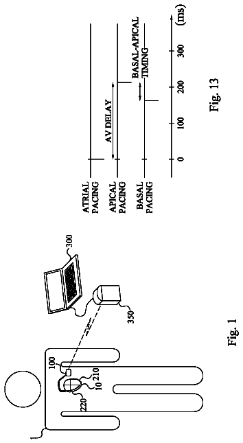
FIG. 1 is a schematic diagram of one embodiment of the present invention implanted bilaterally in a human patient.
FIG. 2 is an architectural block diagram of one embodiment of the neurological control system of the present invention.
FIG. 3 is a block diagram of one embodiment of an intracranial recording electrode (ICRE) signal processor and an intracranial stimulating electrode (ICSE) signal processor each of which are included within the signal processor illustrated in FIG. 2.
FIG. 4 is a schematic diagram of a globus pallidus implanted with stimulating and recording electrodes in accordance with one embodiment of the present invention.
FIG. 5 is a block diagram of one embodiment of an EMG signal processor that is included in one embodiment of the signal processor illustrated in FIG. 2.
FIG. 6 is a block diagram of one embodiment of an EEG signal processor module that is included in one embodiment of the signal processor illustrated in FIG. 2.
FIG. 7 is a block diagram of one embodiment of an accelerometer signal processor that is incorporated into certain embodiments of the signal processor illustrated in FIG. 2.
FIG. 8 is a block diagram of one embodiment of an acoustic signal processor that is included in certain embodiments of the signal processor illustrated in FIG. 2.
FIG. 9 is block diagram of one embodiment of a peripheral nerve electrode (PNE) signal processor 237 that is implemented in certain embodiments of signal processor 71.
FIG. 10 is a schematic diagram of one embodiment of the signal processor illustrated in FIG. 2.
FIG. 11 is a schematic diagram of the patient-neural modulator system illustrated in FIG. 2 illustrated to show its controller and observer components.
FIG. 12 is a schematic diagram of one embodiment of the control circuit illustrated in FIG. 2.
FIG. 13 is a schematic diagram of electrical stimulation waveforms for neural modulation
FIG. 14 is a schematic diagram of one example of the recorded waveforms.
FIG. 15 is a schematic block diagram of an analog switch used to connect one or an opposing polarity pair of Zener diodes across the noninverting and inverting inputs of an intracranial recording electrode amplifier.
Detailed description of the invention
FIG. 1 is a schematic diagram of one embodiment of the intracranial stimulator of the present invention implanted bilaterally in a human patient. In the embodiment illustrated in FIG. 1, two neurological control systems 999 are shown implanted bilaterally. Each system 999 includes a stimulating and recording unit 26 and one or more intracranial components described below. As described in this illustrative embodiment, the intracranial components preferably include a stimulating electrode array 37. However, it should become apparent to those of ordinary skill in the relevant art after reading the present disclosure that the stimulating electrodes may also be extracranial; that is, attached to a peripheral nerve in addition to or in place of being located within the cranium. As shown in FIG. 1, stimulating and recording unit 26 of each neurological control system 999 is preferably implanted contralateral to the intracranial components of the device.
As one skilled in the relevant art would find apparent from the following description, the configuration illustrated in FIG. 1 is just one example of the present invention. Many other configurations are contemplated. For example, in alternative embodiments of the present invention, the stimulating and recording unit 26 is implanted ipsilateral or bilateral to the intracranial components. It should also be understood that the stimulating and recording unit 26 can receive ipsilateral, contralateral or bilateral inputs from sensors and deliver ipsilateral, contralateral, or bilateral outputs to a single or a plurality of intracranial stimulating electrode arrays 37. Preferably, these inputs are direct or preamplified signals from at least one of EMG electrode array 50, EEG electrode array 51, Accelerometer Array 52, Acoustic Transducer Array 53, Peripheral Nerve Electrode Array 54, and Intracranial Recording Electrode Array 38. The signals input from these sensors will be referred to herein as "sensory input modalities" 247. The outputs include but are not limited to one or more stimulating current signals or stimulating voltage signals to Intracranial Stimulating Electrode Array 37.
In the embodiment illustrated in FIG. 1, the two unilateral systems 26 are shown to receive sensory inputs from the side contralateral as well as the intracranial stimulating electrode arrays 37. In the illustrative embodiment, systems 26 also receive sensory inputs from intracranial recording electrode arrays 38. As will become apparent from the following description, intracranial recording electrode arrays 38 may provide valuable feedback information.
It should be understood that this depiction is for simplicity only, and that any combination of ipsilateral, contralateral or bilateral combination of each of the multiple sensory input modalities and multiple stimulation output channels may be employed. In addition, stimulating and recording units 26 may be a single device, two communicating devices, or two independent devices. Accordingly, these and other configurations are considered to be within the scope of the present invention. It is anticipated that stimulating and recording units 26, if implemented as distinct units, would likely be implanted in separate procedures (soon after clinical introduction) to minimize the likelihood of drastic neurological complications.
In the exemplary embodiment illustrated in FIG. 1, the intracranial stimulating electrode array 37 includes a plurality of intracranial stimulating electrodes 1, 2, 3 and 4. Array 37 may, of course, have more or fewer electrodes than that depicted in FIG. 1. These intracranial stimulating electrodes 1-4 may be used to provide stimulation to a predetermined nervous system component. The electrical stimulation provided by the intracranial stimulating electrodes 1-4 may be excitatory or inhibitory, and this may vary in a manner which is preprogrammed, varied in real-time, computed in advance using a predictive algorithm, or determined using another technique now or latter developed.
The intracranial recording electrode arrays 38 includes intracranial recording electrodes 5 and 6. In accordance with one embodiment of the present invention, the intracranial recording electrodes 5, 6 are used to record cortical activity as a measure of response to treatment and as a predictor of impeding treatment magnitude requirements. In the illustrative embodiment, intracranial recording electrodes 5 and 6 are depicted in a location superficial to the intracranial stimulating electrodes 1-4. However, this positioning may be reversed or the intracranial stimulating electrodes 1-4 and intracranial recording electrodes 5 and 6 may be interspersed in alternative embodiments. For example, these electrodes may be placed in at least one of motor cortex, premotor cortex, supplementary motor cortex, other motor cortical areas, somatosensory cortex, other sensory cortical areas, Wernicke's area, Broca's area, other cortical region, other intracranial region, and other extracranial region.
In the illustrative embodiment, an intracranial catheter 7 is provided to mechanically support and facilitate electrical connection between intracranial and extracranial structures. In this embodiment, intracranial catheter 7 contains one or more wires connecting extracranial stimulating and recording circuit 26 to the intracranial electrodes, including but not limited to, intracranial stimulating electrodes 1-4 and intracranial recording electrodes 5, 6. The wires contained within intracranial catheter 7 transmit stimulating electrode output signal (SEOS) to intracranial stimulating electrode array 37. Such wires additionally transmit stimulating electrode input signal (SEIS) and recording electrode input signal (REIS), from intracranial stimulating electrode array 37 and intracranial recording electrode array 38 respectively, to stimulating and recording circuit 26.
Stimulating and recording circuit 26 is protected within a circuit enclosure 44. Circuit enclosure 44 and contained components, including stimulating and recording circuit 26 comprise stimulating and recording unit 43. It should be understood that more or fewer of either type of electrode as well as additional electrode types and locations may be incorporated or substituted without departing from the spirit of the present invention. Furthermore, stimulating and recording circuit 26 can be placed extra cranially in a subclavian pocket as shown in FIG. 1, or it may be placed in other extracranial or intracranial locations.
Connecting cable 8 generally provides electrical connection between intracranial or intracranial locations. A set of electrical wires provides the means for communication between the intracranial and extracranial components; however, it should be understood that alternate systems and techniques such as radiofrequency links, optical (including infrared) links with transcranial optical windows, magnetic links, and electrical links using the body components as conductors, may be used without departing from the present invention. Specifically, in the illustrative embodiment, connecting cable 8 provides electrical connection between intracranial components 246 and stimulating and recording circuit 26. In embodiments wherein stimulating and recording circuit 26 has an intracranial location, connecting cable 8 would likely be entirely intracranial. Alternatively, connecting in embodiments wherein stimulating and recording circuit 26 is implanted under scalp 10 or within or attached to calvarum 9, connecting cable 8 may be confined entirely to subcutaneous region under the scalp 10.
A catheter anchor 29 provides mechanical connection between intracranial catheter 7 and calvarum 9. Catheter anchor 29 is preferably deep to the overlying scalp 10. Such a subcutaneous connecting cable 8 provides electrical connection between intracranial electrodes 246 and stimulating and recording circuit 26. Cable 8 may also connect any other sensors, including but not limited to any of sensory input modalities 247, or other stimulating electrodes, medication dispensers, or actuators with stimulating and recording circuit 26.
Sensory feedback is provided to recording and stimulating unit 26 from a multiplicity of sensors, collectively referred to as sensory input modalities 247. Intracranial recording electrode array 38, previously described, is intracranial in location. Additional sensors, most of which are located extracranially in the preferred embodiment, comprise the remainder of sensory input modalities 247. Sensory input modalities 247 provide information to stimulating and recording unit 26. As will be described in greater detail below, such information is processed by stimulating and recording unit 26 to deduce the disease state and progression and its response to therapy.
In one embodiment of the invention, a head-mounted acoustic sensor 11 is used to monitor any number of vibratory characteristics such as high frequency head vibration, muscle vibration, and/or speech production. Head-mounted acoustic sensor 11 is connected to stimulating and recording circuit 26 with an acoustic sensor connecting cable 30.
A head-mounted accelerometer 12 is implemented in certain embodiments of the present invention to monitor head movement and position with respect to gravity. Head-mounted accelerometer 12 may be mounted to any structure or structures that enables it to accurately sense a desired movement. Such structures include, for example, the skull base, calvarum, clavicle, mandible, extraocular structures, soft tissues and vertebrae. Head-mounted accelerometer 12 is connected to stimulating and recording circuit 26 with an accelerometer connecting cable 31.
A proximal electromyography (EMG) electrode array 45 is also included in certain preferred embodiments of the invention. Proximal EMG electrode array 45 includes a positive proximal EMG electrode 13, a reference proximal EMG electrode 14, and a negative proximal EMG electrode 15. As one skilled in the relevant art would find apparent, proximal EMG electrode array 45 may include any number of type of electrodes. Proximal EMG electrode array 45 is implanted in or adjacent to muscle tissue. In the embodiment illustrated in FIG. 1, proximal EMG electrode array 45 is shown implanted within the neck of the human patient. However, it should be understood that this location is illustrative only and that proximal EMG electrode array 45 may be implanted in or adjacent to any muscle without departing from the spirit of the present invention.
A proximal acoustic sensor 27 may also be implemented in the present invention. Proximal acoustic sensor 27 senses muscle vibration and may be used to augment, supplement or replace EMG recording. Also, a proximal accelerometer 28 may be used to sense movement, including tremor and voluntary activity, and orientation with respect to gravity. Proximal connecting cable 16 provides electrical connection from the proximal EMG electrodes 14 and 15, proximal acoustic sensor 27, and proximal accelerometer 28 to stimulating and recording circuit 26. In the illustrative embodiment, these sensors are shown connected to a common proximal connecting cable 16. However, in alternative embodiments, this configuration may include the use of multiple connecting cables or implement other types of communication media without departing from the present invention. It should also be understood from the preceding description that the number of each type of sensor may also be increased or decreased, some sensor types may be eliminated, and other sensor types may be included without departing from the spirit of the present invention.
A distal EMG electrode array 47 may also be included in certain embodiments of the present invention. In such embodiments, distal EMG electrode array 47 typically includes a positive distal EMG electrode 17, a reference distal EMG electrode 42, and a negative distal EMG electrode 18. Positive distal EMG electrode 17 is connected to stimulating and recording circuit 26 by positive distal EMG connecting cable 20. Negative distal EMG electrode 18 is connected to stimulating and recording circuit 26 by negative distal EMG connecting cable 21. Reference distal EMG electrode 42 is connected to stimulating and recording circuit 26 by reference distal EMG connecting cable 48.
In other embodiments, a distal acoustic sensor 19 is connected to stimulating and recording circuit 26 by distal acoustic connecting cable 22. Distal accelerometer 33 is connected to stimulating and recording circuit 26 by distal accelerometer connecting cable 34. Distal accelerometer 33 is connected to stimulating and recording circuit 26 by distal accelerometer connecting cable 34.
In the embodiment illustrated in FIG. 1, distal EMG electrode array 47, distal acoustic sensor 19, and distal accelerometer 33 are shown located in the shoulder region. However, the distal EMG electrode array 47 may be located in other locations, including, for example, the masseter, temporalis, sternocleidomastoid, other portion of the head and neck, pectoralis, torso, abdomen, upper extremities, lower extremities, and other locations. The number of each type of sensor may be increased or decreased, some sensor types may be eliminated, and other sensor types may be included without departing from the spirit of the present invention.
An enclosure-mounted EMG electrode array 46 is illustrated in FIG. 1. Enclosure-mounted EMG electrode array 46 includes enclosure-mounted positive EMG electrode 23, enclosure-mounted negative EMG electrode 24 and enclosure-mounted reference EMG electrode 25, all of which are attached to the circuit enclosure 44 that encloses stimulating and recording unit 26. The circuit enclosure 44 is preferably included to provide robustness against potential lead entanglement and fracture. In one particular embodiment, circuit enclosure 44 is constructed of titanium and epoxy, or other single or combination of bio-compatible materials. Enclosure-mounted acoustic sensor 35 and enclosure-mounted accelerometer 36 are mounted to stimulating and recording unit 43. The number of each type of sensor may be increased or decreased, their locations changed, some sensor types eliminated, and other sensor types included without departing from the spirit of the present invention.
In the embodiment illustrated in FIG. 1, EEG electrodes 39, 40, 41 are provided. The EEG electrodes may be mounted directly to connecting cable 8 or may be connected via intermediate cables. Any one of the numerous standard and new electrode configurations, or montages, may be employed in EEG electrodes 39-41 without departing from the present invention.
In one embodiment, a proximal peripheral nerve electrode array 98 is connected to stimulating and recording circuit 26 by proximal peripheral nerve electrode array connecting cable 100. Proximal peripheral nerve electrode array 98 is shown located in the neck region. In this location proximal peripheral nerve electrode array 98 can interface with the vagus nerve, spinal accessory nerve, or nerve arising from cervical roots.
A distal peripheral nerve electrode array 99 is connected to stimulating and recording circuit 26 by distal peripheral nerve electrode array connecting cable 32. Distal peripheral nerve electrode array 99 is shown located by the proximal arm, in position to interface with the brachial plexus or proximal arm nerve. One or more of these peripheral nerve electrode arrays may be implanted in these or other locations, including but not limited to the head, cranial nerves, neck, torso, abdomen, upper extremities, and lower extremities, without departing from the present invention.
In one preferred embodiment, the peripheral nerve electrode arrays are each comprised of three epineural platinum-iridium ring electrodes, each in with an internal diameter approximately 30% larger than that of the epineurium, longitudinally spaced along the nerve. Electrodes of differing dimensions and geometries and constructed from different materials may alternatively be used without departing from the present invention. Alternative electrode configurations include but are not limited to epineural, intrafascicular, or other intraneural electrodes; and materials include but are not limited to platinum, gold, stainless steel, carbon, and other element or alloy.
FIG. 2 is an architectural block diagram of one embodiment of the neurological control system 999 of the present invention for modulating the activity of at least one nervous system component in a patient. As used herein, a nervous system component includes any component or structure comprising an entirety or portion of the nervous system, or any structure interfaced thereto. In one preferred embodiment, the nervous system component that is controlled by the present invention includes the globus pallidus internus. In another preferred embodiment, the controlled nervous system component is the subthalamic nucleus.
The neurological control system 999 includes one or more implantable components 249 including a plurality of sensors each configured to sense a particular characteristic indicative of a neurological or psychiatric condition. One or more intracranial (IC) stimulating electrodes in an IC stimulating electrode array 37 delivers a neural modulation signal to the same or other nervous system component as that being monitored by the system 26. One or more sensors 38, 51, 52, 53, and 54 sense the occurrence of neural responses to the neural modulation signals. Stimulating and recording unit 26 generates the neural modulation signal based on the neural response sensed by the sensors.
The neurological control system 999 preferably also includes a patient interface module 55 and a supervisory module 56. A control circuit 72 (described below) is communicably coupled to the patient interface module 55 and receives signal inputs from and provides signal outputs to patient interface module 55 and supervisory module 56. In one preferred embodiment, patient interface module 55 and supervisory module 56 remain external to the body of the patient. However either of these devices may be connected via percutaneous leads or be partially or totally implanted without departing from the present invention.
Patient interface module 55 and supervisory module 56 facilitate adjustment of control parameters, monitoring of disease state, monitoring of response to therapy, monitoring of stimulating and recording circuit 26, monitoring of impedance and other characteristics of intracranial stimulating electrode array 37, monitoring of physiologic parameters, monitoring of vital signs, monitoring of any other characteristic or function of components of the present invention, including but not limited to the stimulating and recording circuit 26, stimulating and recording unit 43, circuit enclosure 44, EMG electrode array 50, EEG electrode array 51, accelerometer array 52, acoustic transducer array 53, peripheral nerve electrode array 54, and intracranial recording electrode array 38. Such monitoring and adjustment is accomplished through the use of any well known bi-directional communication between control circuit 72 and supervisory module 56. In one preferred embodiment, a radio frequency link is employed. In alternative embodiments, other communication technologies, including but not limited to optical, percutaneous, or electromagnetic, may be used.
In one preferred embodiment, patient interface module 55 and supervisory module 56 are placed adjacent to the patients garments overlying the implanted stimulating and recording unit 43. When neurological control system 999 is turned on in this position, a communications handshaking protocol is executed. Communication handshaking routines are known to those or ordinary skill in the art, and they enable establishment of a communication rate and protocol and facilitate mutual identification of devices. Patient interface module 55 automatically downloads parameters from stimulating and recording circuit 26 and stores values of such parameters in a memory. When the transfer of these parameter values is complete, patient interface module 55 emits a audible signal such as a series of beeps, and the patient turns off patient interface module 55 and removes it from its position overlying the implanted stimulating and recording unit 43. Parameter values may then be retrieved by the patient by a routine including but not limited to a menu driven interface, and the values may be transmitted via telephone conversation or other communication method to a health care professional. Supervisory module 56 operates in the same manner with one addition; a step is provided during which the health care professional may upload parameters to stimulating and recording circuit 26 to alter its function including by means of changing parameters including but not limited to control laws gains and thresholds, filter parameters, signal processing parameters, stimulation waveform modes (including at least one of current regulated, voltage regulated, frequency regulated, or pulse width regulated), and stimulation waveform parameters.
The description continues in the full USPTO document.
 Lapsed, fee not paid8 drawings