Lapsed, fee not paid12 drawings
Telecom & Networks · US 8,780,782 B2
Method and apparatus for handling radio link failure in LTE eMBMS
A method, an apparatus, and a computer program product for wireless communication are provided.
US 8,780,797 B2 · Assignee: Cellco Partnership · Inventors: Chen; Xuming et al.
Sheet 1 of 20 from the published document. All sheets in the USPTO PDF
A universal integrated circuit card (UICC) may include a universal subscriber identity module (USIM); a code division multiple access (CDMA) subscriber identity module (CSIM); a memory to store instructions; and a processor. The processor may execute instructions to determine a type of wireless access network available to a user equipment (UE) associated with the UICC; perform activation of the UICC using the USIM, in response to detecting a CDMA enhanced High Rate Packet Data (eHRPD) network, a Global System for Mobile Communication (GSM) access network, or a Long Term Evolution (LTE) access network; and perform activation of the UICC using the CSIM, in response to detecting an available CDMA access network other than a CDMA eHRPD access network.
Mobile wireless communication devices continue to increase in popularity, leading to increasing numbers of users and to demands for more services and higher data rates. In order to satisfy the needs of users and to improve service, providers of mobile wireless communication services continue to improve wireless access networks, as well as core networks, used to deliver services for users of mobile communication devices. One aspect of such improvements may include the development of access networks based on newer standards, protocols, and/or technologies. While a service provider may update an access network in a particular geographic area to a new generation access network, by, for example, installing a new base station, other geographic areas may continue to be served by an older generation network. A new generation access network may operate under different protocols, use different sta
1 of 20 drawing sheets so far from the published document, cropped to the drawing. Every sheet is in the USPTO PDF.
What the patent claimed, word for word. All of it is now free to use.
Mobile wireless communication devices continue to increase in popularity, leading to increasing numbers of users and to demands for more services and higher data rates. In order to satisfy the needs of users and to improve service, providers of mobile wireless communication services continue to improve wireless access networks, as well as core networks, used to deliver services for users of mobile communication devices. One aspect of such improvements may include the development of access networks based on newer standards, protocols, and/or technologies.
While a service provider may update an access network in a particular geographic area to a new generation access network, by, for example, installing a new base station, other geographic areas may continue to be served by an older generation network. A new generation access network may operate under different protocols, use different standards, or include different network nodes than an older generation network.
A mobile communication device, referred to herein as user equipment (UE), may include a subscriber identity module (SIM), which may be used by an access network, and/or a core network, to identify a user of the UE. In a hybrid network, which includes an older generation access network and a new generation access network, management of a SIM may prove to be particularly troublesome.
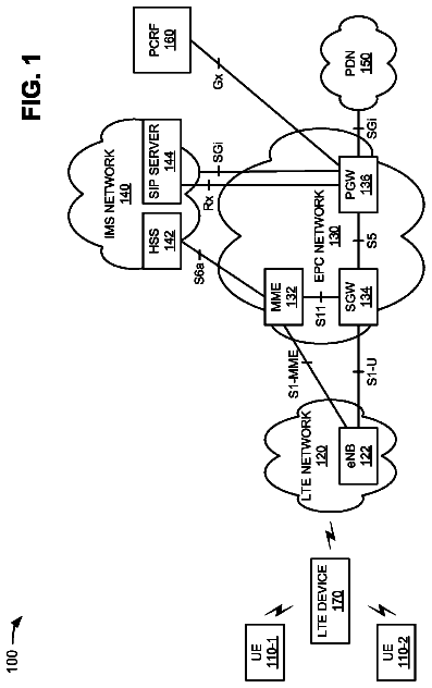
FIG. 1 is a diagram illustrating example components of a system according to an implementation described herein;
FIG. 2 is a diagram illustrating example components of a UE according to an implementation described herein;
FIG. 3A is a diagram illustrating example components of the universal integrated circuit card (UICC) depicted in FIG. 2;
FIG. 3B is a diagram illustrating example components of the Universal SIM (USIM), Internet Protocol Multimedia Subsystem SIM (ISIM), or Code Division Multiple Access SIM (CDMA) depicted in FIG. 3A;
FIG. 4 is a diagram illustrating example components of the billing system, provisioning system, or programming system of FIG. 1;
FIG. 5A is a diagram illustrating example functional components of the provisioning system of FIG. 1;
FIG. 5B is a diagram illustrating example functional components of the programming system of FIG. 1;
FIG. 5C is a diagram illustrating example functional components of the UICC depicted in FIG. 3A;
FIG. 6 is a diagram of example fields that may be stored within the databases depicted in FIG. 5C according to an implementation described herein;
FIG. 7 is a flow diagram illustrating an example process performed by the billing system, in response to a purchase, according to an implementation described herein;
FIG. 8 is a flow diagram illustrating an example process performed by the provisioning system, in response to being contacted by the billing system, according to an implementation described herein;
FIG. 9 is a diagram illustrating an example signal flow at the back end of the network, in response to a purchase, according to an implementation described herein;
FIG. 10 is a flow diagram illustrating an example process of authentication bypass under High Rate Packet Data (HRPD) coverage, performed by the UICC, according to an implementation described herein;
FIG. 11 is a diagram illustrating an example signal flow of the authentication bypass under HRPD coverage according to an implementation described herein;
FIG. 12 is a flow diagram illustrating an example process of authentication bypass under enhanced HRPD coverage, performed by the UICC, according to an implementation described herein;
FIG. 13 is a diagram illustrating an example signal flow of the authentication bypass under eHRPD coverage according to an implementation described herein;
FIG. 14 is a flow diagram illustrating an example process of UICC activation, performed by the programming system, according to an implementation described herein;
FIGS. 15A and 15B are flow diagrams illustrating an example process of UICC activation, performed by the UICC, according to an implementation described herein;
FIG. 16A is a diagram illustrating an example signal flow of UICC activation under CDMA one times radio transmission technology (1.times.RTT) coverage according to an implementation described herein;
FIG. 16B is a diagram illustrating an example signal flow of UICC activation under HRPD coverage according to an implementation described herein; and
FIG. 16C is a diagram illustrating an example signal flow of UICC activation under Long Term Evolution (LTE) or eHRPD coverage according to an implementation described herein.
The following detailed description refers to the accompanying drawings. The same reference numbers in different drawings identify the same or similar elements. Also, the following detailed description does not limit the invention.
An implementation described herein may relate to a universal integrated circuit (IC) card (UICC) activation. A UICC may include one or more SIMs. A SIM identifies a subscriber in a particular access network. A subscriber may switch UEs by removing the SIM from a first UE and placing the SIM in a second UE. A UICC may include a code division multiple access (CDMA) SIM (CSIM), an Internet Protocol (IP) Multimedia Subsystem (IMS) SIM (ISIM), and a universal SIM (USIM). A CSIM may be used for authentication in CDMA mode, under CDMA 1.times.RTT coverage and under CDMA high rate packet data (HRPD) coverage. An ISIM may be used in connection with an IMS network, and may not be utilized during UICC activation. A USIM may be used in CDMA mode under enhanced HRPD (eHRPD) coverage, in Global System for Mobile Communication (GSM) mode, and in Long Term Evolution (LTE) mode. Thus, UICC activation may be performed in either CDMA or GSM/LTE mode.
Under CDMA 1.times.RTT coverage, over the air special provisioning (OTASP) may be performed, using an over the air function (OTAF) number stored in the CSIM, to perform authentication and establish 1.times.RTT IP connectivity. Under HRPD coverage, a special network access identifier (NAI), stored in the CSIM, may be used to bypass both access network authentication and packet data network (PDN) gateway authentication and establish IP connectivity. Under eHRPD coverage, the special NAI may be used to bypass access network authentication and an NAI, derived from an International Mobile Subscriber Identity (IMSI), may be used for PDN gateway authentication.
FIG. 1 is a diagram illustrating example components of a system 100 according to an implementation described herein. As shown in FIG. 1, system 100 may include a UE 101, a CDMA access network 122, a Global System for Mobile Communications (GSM) access network 124, a Long Term Evolution (LTE) access network 126, a core network 140, a home location register (HLR) 152, an authentication, authorization, and accounting (AAA) server 154, a home subscriber server (HSS) 156, an over the air function (OTAF) 162, back end system 170, a provisioning system 180, and a programming system 190.
UE 101 may include any wireless communication device that a user may use to connect to a CDMA base station 112, GSM base station 114, and/or eNodeB 116. Thus, UE 101 may include a dual mode UE capable of operating in both CDMA mode and in GSM and/or LTE mode. UE 101 may include, for example, a mobile communication device, such as a mobile phone, a personal digital assistant (PDA), or a media playing device with communication capabilities; a desktop device, such as a personal computer or a workstation; a laptop computer; a telephone terminal; or any other communication device or combinations thereof
UE 101 may include a universal integrated circuit card (UICC) 102. UICC 102 may include information that identifies a particular subscription to system 100 (e.g., a particular customer). UICC 102 may include a CSIM, a USIM, and an ISIM and may need to be activated to allow UE 101 to operate in system 100. UICC 102 may be removed from UE 101 and may be and installed in a new UE.
CDMA access network 122 may include an access network based on, for example, a CDMA2000 standard. For example, CDMA access network may include a CDMA one times radio transmission technology (1.times.RTT) network, a CDMA HRPD network (which may include a CDMA evolution optimized data only (EV-DO) network), or a CDMA eHRPD network (which may provide access to LTE access network 126).
CDMA access network 122 may include a CDMA base station 112, a packet data service node (PDSN) 121, and a home agent (HA) 132. CDMA base station 112 may include a wireless transceiver and may include functionality necessary to establish a wireless connection between UE 101 and CDMA access network 122. For example, CDMA base station 112 may include a CDMA 1.times.RTT base station, a CDMA HRPD base station, and/or a CDMA eHRPD base station.
PDSN 121 may provide an access point to and from UE 101 may handle forwarding of data packets for UE 101, and may act as a local anchor point during handover procedures. HA 132 may function as a gateway to an IP network (e.g., core network 140). HA 132 may assign an IP address to UE 101.
GSM access network 124 may include an access network based on a GSM standard. For example, GSM access network 124 may include a General Packet Radio Service (GPRS) network, an Enhanced Data Rates for GSM Evolution (EDGE) network, a Universal Mobile Telecommunications System (UMTS) network (also known as a wideband CDMA (W-CDMA) network), or a High Speed Packet Access (HSPA) network. GSM access network 122 may include GSM base station 114, a Serving General Packet Radio Service (GPRS) Support Node (SGSN) 123, and a Gateway GPRS Support Node (GGSN) 134.
GSM base station 114 may include a wireless transceiver and may include functionality necessary to establish a wireless connection between UE 101 and GSM access network 124. SGSN 123 may provide an access point to and from UE 101 may handle forwarding of data packets for UE 101 and act as a local anchor point during handover procedures. GGSN 134 may function as a gateway to an IP network (e.g., core network 136). GGSN 134 may assign an IP address to UE 101.
LTE access network 126 may include an access network (e.g., an evolved packet core (EPC) network) based on the LTE standard specified by the 3.sup.rd Generation Partnership Project (3GPP). LTE access network 126 may include one or more devices that implement logical entities interconnected via standardized interfaces and that provide packet-switched services between UE 101 and core network 140. LTE access network 126 may include an eNodeB 116, a serving gateway (SGW) 125, and a packet data network gateway (PGW) 136.
eNodeB 116 may include a wireless transceiver and may include functionality necessary to establish a wireless connection between UE 101 and LTE access network 126. SGW 125, may provide an access point to and from UE 101 and may handle forwarding of data packets for UE 101, and may act as a local anchor point during hand-over procedures between different eNodeBs. PGW 136 may function as a gateway to an IP network (e.g., core network 140). UE 101, while connected to a single SGW 125, may be connected to multiple PGWs 136 (e.g., one for each IP network with which UE device 101 communicates). PGW 136 may assign an IP address to UE 101.
Core network 140 may allow the delivery of Internet Protocol (IP) broadband services to UE 101, and may interface with other external networks. Core network 140 may include one or more server devices and/or network devices, or other types of computation or communication devices. Core network 140 may include a local area network (LAN), a wide area network (WAN), a metropolitan area network (MAN), an optical network, a cable television network, a satellite television network, a wireless network (e.g., a Code Division Multiple Access (CDMA) network, a general packet radio service (GPRS) network, and/or an LTE network), an ad hoc network, a telephone network (e.g., the Public Switched Telephone Network (PSTN) or a cellular network), an intranet, the Internet, or a combination of networks.
In one example implementation, core network 140 may include an IMS network (not shown in FIG. 1). An IMS network may include a network for delivering IP multimedia services as specified by 3GPP and may provide media flows between UE device 101 and external IP networks or external circuit-switched networks (not shown in FIG. 1). Core network 140 may allow CDMA access network 122, GSM access network 124, and LTE access network 126 to communicate with HLR 152, AAA server 154, HSS 156, OTAF 162, back end system 170, provisioning system 180, programming system 190, and SMS center 195.
HLR 152 may include one or more devices that store information about subscribers of CDMA access network 122 and/or GSM access network 124. For example, HLR 152 may store information associated with a UICC associated with a subscriber, services that the subscriber has requested or been assigned and settings associated with the services, and/or a current location of the subscriber.
AAA server 154 may include one or more devices that perform authentication, authorization, and/or accounting in system 100. For example, AAA server 154 may verify a subscriber's identity, authorize access to a particular access network or access to core network 140, authorize a particular service, and/or track consumption of network resources for a particular subscriber.
HSS 156 may include one or more devices that store information about subscribers of LTE access network 126. For example, HSS 156 may store information associated with a UICC associated with a subscriber, services that the subscriber has requested or been assigned and settings associated with the services, and/or a current location of the subscriber.
OTAF 162 may include one or more devices that perform service provisioning in a CDMA 1.times.RTT network. For example, OTAF 162 may receive a request for service provisioning from UE 101 to access a CDMA 1.times.RTT access network and may grant access to the CDMA 1.times.RTT access network to UE 101.
Back end system 170 may include one or more devices involved in processing of UICC 102 when a customer purchases a new subscription. Back end system 170 may include a device management database (DMD) 171, a point of sale system (POS) 172, an electronic telephone number directory (eTNI) 173, a key storage system 174, and a billing system 175.
DMD 171 may store information about UE 101 and associate UE 101 with UICC 102. For example, when UICC 102 is installed in a new UE, DMD 171 may receive information about the new UE from provisioning system 180 and store the received information. DMD 171 may store information about capabilities of UE 101 and provide the information about the capabilities of UE 101 to POS 172.
POS 172 may include one or more devices that communicate with system 100 when a customer purchases UE 101 or requests a new subscription for services associated with system 100. For example, POS 172 may include a terminal associated with a sales clerk in a retail store.
eTNI 173 may store information about available telephone and/or identification numbers. For example, eTNI 173 may receive a request from POS 172 for available telephone and/or identification numbers during the creation of a new subscription and may provide to POS 172 an available Mobile Subscriber Integrated Services Digital Network number (MSISDN), an available International Mobile Subscriber Identity (IMSI) number, and/or an available mobile identification number (MIN).
Key storage system 174 may include one or more devices that store keys used for provisioning services for a new subscription. For example, key storage system 174 may store keys used by provisioning system 180 to authenticate communication with HLR 152, AAA 154, HSS 156, and/or programming system 190.
Billing system 175 may include one or more devices that perform billing functions in system 100. For example, billing system 175 may receive a request from POS 172 to set up a new subscription, determine particular services requested by the customer, send a request to provisioning system 180 to set up the requested services, and/or set up billing for the requested services.
Provisioning system 180 may include one or more devices that perform provisioning services in system 100. For example, provisioning system 180 may request HLR 152, AAA 154, and HSS 156 to create accounts associated with UICC 102 and to store information associated with UICC 102. Furthermore, provisioning system 180 may provide information about UICC 102 to programming system 190 to allow programming system 190 to activate UICC 102.
Programming system 190 may include one or more devices that perform activation of UICC 102. For example, programming system 190 may receive an activation request from UICC 102 and may provide updated files for a USIM, ISIM, and CSIM included in UICC 102, as well as application configuration updates for UICC 102.
Although FIG. 1 shows example components of system 100, in other implementations, system 100 may include fewer components, different components, differently arranged components, or additional components than depicted in FIG. 1. Additionally or alternatively, one or more components of system 100 may perform the tasks described as being performed by one or more other components of system 100.
FIG. 2 is a diagram illustrating example components of UE 101 according to an implementation described herein. As shown in FIG. 2, UE 101 may include a processing unit 210, a memory 220, a user interface 230, a communication interface 240, an antenna assembly 250, and UICC 102.
Processing unit 210 may include one or more processors, microprocessors, application specific integrated circuits (ASICs), field programmable gate arrays (FPGAs), or the like. Processing unit 210 may control operation of UE 101 and its components.
Memory 220 may include a random access memory (RAM), a read only memory (ROM), and/or another type of memory to store data and instructions that may be used by processing unit 210.
User interface 230 may include mechanisms for inputting information to UE 101 and/or for outputting information from UE 101. Examples of input and output mechanisms might include a speaker to receive electrical signals and output audio signals; a camera lens to receive image and/or video signals and output electrical signals; a microphone to receive audio signals and output electrical signals; buttons (e.g., a joystick, control buttons, or keys of a keypad) to permit data and control commands to be input into UE 101; a display to output visual information; and/or a vibrator to cause UE 101 to vibrate.
Communication interface 240 may include any transceiver-like mechanism that enables UE 101 to communicate with other devices and/or systems. For example, communication interface 240 may include a modem or an Ethernet interface to a local area network (LAN). Communication interface 240 may also include mechanisms for communicating via a network, such as a wireless network. For example, communication interface 240 may include, for example, a transmitter that may convert baseband signals from processing unit 210 to radio frequency (RF) signals and/or a receiver that may convert RF signals to baseband signals. Alternatively, communication interface 240 may include a transceiver to perform functions of both a transmitter and a receiver. Communication interface 240 may connect to antenna assembly 250 for transmission and/or reception of the RF signals.
Antenna assembly 250 may include one or more antennas to transmit and/or receive RF signals over the air. Antenna assembly 250 may, for example, receive RF signals from communication interface 240 and transmit them over the air and receive RF signals over the air and provide them to communication interface 240. In one implementation, for example, communication interface 240 may communicate with CDMA access network 122, GSM access network 124, LTE access network 126, or with another access network.
As described herein, UE 101 may perform certain operations in response to processing unit 210 executing software instructions contained in a computer-readable medium, such as memory 220. A computer-readable medium may be defined as a physical or logical memory device. A logical memory device may include memory space within a single physical memory device or spread across multiple physical memory devices. The software instructions may be read into memory 220 from another computer-readable medium or from another device via communication interface 240. The software instructions contained in memory 220 may cause processing unit 210 to perform processes that will be described later. Alternatively, hardwired circuitry may be used in place of or in combination with software instructions to implement processes described herein. Thus, implementations described herein are not limited to any specific combination of hardware circuitry and software.
Processing unit 210 may communicate with UICC 102. For example, processing unit 210 may receive instructions from UICC 102 and may perform the received instructions. For example, UICC 102 may instruct processing unit 210 to provide particular information to a particular component of system 100 via communication interface 240 and/or to request particular information from a particular component of system 100. As another example, processing unit 210 may receive, via communication interface 240, particular information for UICC 102 from a particular component of system 100 and/or may receive a request for particular information from UICC 102 from a particular component of system 100. As yet another example, when UE 101 powers up, UICC 102 may take control and may instruct processing unit 210 to perform one or more operations.
Although FIG. 2 shows example components of UE 101, in other implementations, UE 101 may include fewer components, different components, differently arranged components, or additional components than depicted in FIG. 2. Additionally or alternatively, one or more components of UE 101 may perform the tasks described as being performed by one or more other components of UE 101.
FIG. 3A is a diagram illustrating example components of UICC 102. As shown in FIG. 3A, UICC 102 may include a housing 310, contacts 320, and an integrated circuit (IC) area 330. Housing 310 may protect IC area 330 from outside elements. Housing 310 may include a structure configured to hold contacts 320 and IC area 330, and may be formed from a variety of materials. For example, housing 330 may be formed from plastic, metal, or a composite. Contacts 320 may include one or more contacts to electronically connect UICC 102 to UE 101. Contacts 320 may include a power contact to supply electrical power from UE 101 to UICC 102.
IC area 330 may include a Universal SIM (USIM) 340, an IMS SIM (ISIM) 350, and a CDMA SIM (CSIM) 360. USIM 340 may store subscriber information and authentication information for accessing GSM access network 124 and for accessing LTE access network 126. USIM 340 may also include storage space for SMS messages and contacts. ISIM 350 may store a subscriber's IMS identity, such as a public IMS identity and a private IMS identity. CSIM 360 may store subscriber information and authentication information for accessing CDMA access network 122.
Although FIG. 3A shows example components of UICC 102, in other implementations, UICC 102 may include fewer components, different components, differently arranged components, or additional components than depicted in FIG. 3A. Additionally or alternatively, one or more components of UICC 102 may perform the tasks described as being performed by one or more other components of UICC 102.
FIG. 3B is a diagram illustrating example components of USIM 340, ISIM 350, or CSIM 360. As shown in FIG. 3B, USIM 340, ISIM 350, or CSIM 360 may include a bus 332, a processor 334, a memory 336, and a communication interface 338.
Bus 332 may include a path that permits communication among the components of USIM 340, ISIM 350, or CSIM 360. Processor 334 may include one or more processors, microprocessors, or processing logic (e.g., ASICs or FPGAs) that may interpret and execute instructions. Memory 336 may include a RAM device or another type of dynamic storage device that may store information and instructions for execution by processor 334 or a ROM device or another type of static storage device that may store static information and instructions for use by processor 334. Communication interface 338 may include any interface mechanism that enables, USIM 340, ISIM 350, or CSIM 360 to communicate with UE 101.
As will be described in detail below, USIM 340, ISIM 350, or CSIM 360 may perform certain operations. USIM 340, ISIM 350, or CSIM 360 may perform these operations in response to processor 334 executing software instructions contained in a computer-readable medium, such as memory 336.
The software instructions may be read into memory 336 from another computer-readable medium, or from another device via communication interface 338. The software instructions contained in memory 336 may cause processor 334 to perform processes that will be described later. Alternatively, hardwired circuitry may be used in place of or in combination with software instructions to implement processes described herein. Thus, implementations described herein are not limited to any specific combination of hardware circuitry and software.
Although FIG. 3B shows example components of USIM 340, ISIM 350, or CSIM 360, in other implementations, USIM 340, ISIM 350, or CSIM 360 may include fewer components, different components, differently arranged components, or additional components than depicted in FIG. 3B. Additionally or alternatively, one or more components of USIM 340, ISIM 350, or CSIM 360 may perform the tasks described as being performed by one or more other components of USIM 340, ISIM 350, or CSIM 360.
FIG. 4 is a diagram illustrating example components of billing system 175, provisioning system 180, or programming system 190. As shown in FIG. 4, billing system 175, provisioning system 180, or programming system 190 may include a bus 410, a processor 420, a memory 430, an input device 440, an output device 450, and a communication interface 460.
Bus 410 may include a path that permits communication among the components of billing system 175, provisioning system 180, or programming system 190. Processor 420 may include one or more processors, microprocessors, or processing logic (e.g., ASICs or FPGAs) that may interpret and execute instructions. Memory 430 may include a RAM device or another type of dynamic storage device that may store information and instructions for execution by processor 420, a ROM device or another type of static storage device that may store static information and instructions for use by processor 420, a magnetic and/or optical recording memory device and its corresponding drive, and/or a removable form of memory, such as a flash memory.
Input device 440 may include a mechanism that permits an operator to input information to billing system 175, provisioning system 180, or programming system 190, such as a keypad, a button, a pen, a touch screen, voice recognition and/or biometric mechanisms, etc. Output device 450 may include a mechanism that outputs information to the operator, such as a display, a speaker, etc. Communication interface 460 may include any transceiver-like mechanism that enables billing system 175, provisioning system 180, or programming system 190 to communicate with other devices and/or systems. For example, communication interface 460 may include a modem, a network interface card, or a wireless interface card.
As will be described in detail below, billing system 175, provisioning system 180, or programming system 190 may perform certain operations. Billing system 175, provisioning system 180, or programming system 190 may perform these operations in response to processor 420 executing software instructions contained in a computer-readable medium, such as memory 430.
The software instructions may be read into memory 430 from another computer-readable medium, or from another device via communication interface 460. The software instructions contained in memory 430 may cause processor 420 to perform processes that will be described later. Alternatively, hardwired circuitry may be used in place of or in combination with software instructions to implement processes described herein. Thus, implementations described herein are not limited to any specific combination of hardware circuitry and software.
Although FIG. 4 shows example components of billing system 175, provisioning system 180, or programming system 190, in other implementations, billing system 175, provisioning system 180, or programming system 190 may include fewer components, different components, additional components, or differently arranged components than depicted in FIG. 4. Additionally or alternatively, one or more components of billing system 175, provisioning system 180, or programming system 190 may perform one or more tasks described as being performed by one or more other components of billing system 175, provisioning system 180, or programming system 190.
FIG. 5A is a diagram illustrating example functional components of provisioning system 180. As shown in FIG. 5A, provisioning system 180 may include a key retrieval component 510, an HLR provisioning component 522, an AAA provisioning component 524, an HSS provisioning component 526, and a programming system provisioning component 528.
Key retrieval component 510 may contact key storage system 174 to retrieve keys associated with HRL provisioning, AAA provisioning, HSS provisioning, and/or programming system 190 provisioning. HLR provisioning component 522 may perform HLR provisioning. For example, HLR provisioning component 522 may contact HLR 152 and request that a new account be created for a user associated with UICC 102. HLR provisioning component may provide, to HLR 152, particular keys received from key retrieval component 510 when requesting the creation of the account.
AAA provisioning component 524 may perform AAA provisioning. For example, AAA provisioning component 524 may contact AAA 154 and request that a new account be created for a user associated with UICC 102. AAA provisioning component 524 may provide, to AAA 154, particular keys received from key retrieval component 510 when requesting the creation of the account.
HSS provisioning component 526 may perform HSS provisioning. For example, HSS provisioning component 526 may contact HSS 156 and request that a new account be created for a user associated with UICC 102. HSS provisioning component 526 may provide, to HSS 156, particular keys received from key retrieval component 510 when requesting the creation of the account.
Programming system provisioning component 528 may perform provisioning associated with programming system 190. For example, programming system provisioning component 528 may contact programming component 190 and request that a new account be created for a user associated with UICC 102. Programming system provisioning component 528 may provide, to programming system 190, particular keys received from key retrieval component 510 when requesting the account. Additionally, programming system provisioning component 528 may provide USIM, ISIM, CSIM, and application configuration files to programming system 190 that are to be sent to UICC 102 during activation of UICC 102.
Although FIG. 5A shows example functional components of provisioning system 180, in other implementations, provisioning system 180 may include fewer functional components, different functional components, differently arranged functional components, or additional functional components than depicted in FIG. 5A. Additionally or alternatively, one or more functional components of provisioning system 180 may perform one or more other tasks described as being performed by one or more other functional components of provisioning system 180.
FIG. 5B is a diagram illustrating example functional components of programming system 190. As shown in FIG. 5B, programming system 190 may include a card activation component 530, a USIM database 542, a CSIM database 544, a ISIM database 546, an application configuration database 548, and a UE database 550.
Card activation component 530 may perform activation of UICC 102. For example, during UICC activation, card activation component 530 may provide, to UICC 102, information stored in USIM database 542, CSIM database 544, ISIM database 546, and/or application configuration database 548. Card activation component 530 may receive information from UICC 102 about UE 101 and store the received information in UE database 550.
USIM database 542 may store files that are to be provided to USIM 340 during activation of UICC 102. ISIM database 544 may store files that are to be provided to ISIM 350 during activation of UICC 102. CSIM database 546 may store files that are to be provided to CSIM 360 during activation of UICC 102. Application configuration database 548 may store application configuration files that are to be provided to UICC 102 during activation of UICC 102. UE database 550 may store information about UE 101 that may be received from UICC 102 during activation or after UICC is placed into a new UE.
Although FIG. 5B shows example functional components of programming system 190, in other implementations, programming system 190 may include fewer functional components, different functional components, differently arranged functional components, or additional functional components than depicted in FIG. 5B. Additionally or alternatively, one or more functional components of programming system 190 may perform one or more other tasks described as being performed by one or more other functional components of programming system 190.
FIG. 5C is a diagram illustrating example functional components of UICC 102. As shown in FIG. 5C, UICC 102 may include a device information component 560, a UE database 565, a card activation component 570, a USIM database 572, a CSIM database 574, an ISIM database 576, an application configuration database 578, a polling agent 580, and a polling database 585.
Device information component 560 may determine information associated with UE 101 and store the information in UE database 565. UE database 565 may store information associated with UE 101. Example fields that may be stored in UE database 565 are described below with reference to FIG. 6. Card activation component 570 may send a request to programming system 190 to request activation of UICC 102, may receive file updates from programming system 190, and may store the file updates in USIM database 572, CSIM database 574, ISIM database 576, and application configuration database 578.
USIM database 572 may store information used by UICC 102 during communication with GSM access network 124 or LTE access network 126. CSIM database 574 may store information used by UICC 102 during communication with CDMA access network 122. ISIM database 576 may store information used by UICC 102 during communication with an IMS network. Application configuration database 578 may store information about associated with particular applications and/or settings associated with UE 101. Example fields that may be stored in USIM database 572, CSIM database 574, ISIM database 576, and application configuration database 578 are described below with reference to FIG. 6.
Polling agent 580 may detect, based on accessing polling database 585, a trigger event for requesting that UICC 102 be updated and may send a polling request for updates to programming system 190. Polling agent 580 may receive file updates from programming system 190 and may update USIM database 572, CSIM database 574, ISIM database 576, and application configuration database 578 based on the received file updates. Polling database 585 may store information about trigger events for requesting updates. For example, polling database 585 may store particular dates and times when polling agent 580 is to request an update.
Although FIG. 5C shows example functional components of UICC 102, in other implementations, UICC 102 may include fewer functional components, different functional components, differently arranged functional components, or additional functional components than depicted in FIG. 5C. Additionally or alternatively, one or more functional components of UICC 102 may perform one or more other tasks described as being performed by one or more other functional components of UICC 102.
FIG. 6 is a diagram of example fields that may be included within the databases depicted in FIG. 5C. As shown in FIG. 6, UE database 565 may include an Integrated Circuit Card Identification (ICCID) field 601, an International Mobile Equipment Identification (IMEI) field 602, a UE profile 603, and an activation flag field 604.
ICCID field 601 may store an ICCID associated with UICC 102. The ICCID may include a string that uniquely identifies UICC 102 to system 100. IMEI field 602 may include an IMEI associated with UE 101. The IMEI may uniquely identify UE 101 to system 100. Additionally or alternatively, IMEI field 602 may store an IMEI and a software version associated with UE 101 (IMEI_SV). UE profile 603 may store information associated with UE 101, such as capabilities of UE 101 and/or metrics associated with UE 101 that may be used by system 100 to optimize the performance of UE 101. Activation flag field 604 may store information about whether UICC 102 has been activation. For example, after UICC 102 has been activation, an activation flag stored in activation flag field 604 may be set.
As shown in FIG. 6, USIM database 572 may include an MSISDN field 610, an IMSI field 611, a home public land mobile network (HPLMN) field 612, an operation PLMN (OPLMN) field 614, a forbidden PLMN (FPLMN) field 616, an SMS platform (SMSP) field 618, and a mobile country code list (MCCLIST) field 620.
MSISDN field 610 may store an MSISDN associated with the user of UICC 102. The MSISDN may uniquely identify a subscription to system 100. IMSI field 611 may store an IMSI number associated with UICC 102. The IMSI number may uniquely identify a user to system 100. The IMSI number may include an MCC that identifies a country associated with the user and a Mobile Network Code (MNC) associated with the user.
HPLMN field 612 may store a HPLMN (e.g., service provider) associated with the user of UICC 102. OPLMN field 614 may store an OPLMN (e.g., a PLMN associated with administrative and monitoring functions) associated with the user of UICC 102. FPLMN field 616 may store a FPLMN (e.g., a PLMN accessible only during emergencies) associated with the user of UICC 102. SMSP field 618 may identify SMS center 195. MCCLIST field 620 may identify a list of countries in which UICC 102 may operate.
As shown in FIG. 6, CSIM database 574 may include a MIN field 630, a mobile directory number (MDN) field 632, a preferred roaming list (PRL) field 634, a 1.times.RTT access profile field 635, an HRPD access profile field 636, a simple IP user profile 638, and a mobile IP user profile 640.
The description continues in the full USPTO document.
About 6,246 words. The USPTO PDF has it with every drawing.
Fees are due 3.5, 7.5 and 11.5 years after grant. This patent expired on July 15, 2026, so the fee marked "not paid" was the one that went unpaid.
UNIVERSAL INTEGRATED CIRCUIT CARD ACTIVATION IN A HYBRID NETWORK
Filed Oct 2010 · published May 2012Universal integrated circuit card activation in a hybrid network
Filed Oct 2010 · granted Jul 2014Earlier publications, parents and continuations. None of them can still be enforced, or this patent would not be listed.
Prior art cited by the examiner or applicant. Useful when you check your own idea for novelty.
Everything on this page comes from the documents linked above.