Related applications
This application is a 35 U.S.C. .sctn.371 national stage filing of PCT Application No. PCT/KR2009/001255 filed on Mar. 12, 2009, which claims priority to, and the benefit of, U.S. Provisional Application No. 61/035,801 filed on Mar. 12, 2008 and U.S. Provisional Application No. 61/140,312 filed on Dec. 23, 2008. The contents of the aforementioned applications are hereby incorporated by reference.
Technical field
The present invention relates to a mobile RFID interrogator and a control method thereof, and more particularly, to an RFID interrogator that can perform command retransmission depending on a collision type and adaptively set a wait time for the command retransmission and a control method thereof.
Background art
An RFID radio interface specification (i.e., ISO/IEC 18000-6) is developed to include an RFID architecture (i.e., RFID portals), to remarkably reduce a communication error generated due to an inter-tag interference, etc. while easily detecting and controlling the communication error.
However, recently, as a handheld-based RFID interrogator occupies a great part, a necessity for a technique to secure effective use of an RFID technology in a mobile application is on the rise. In particular, compared with most of static scenarios, a position and local arrangement of an active mobile device, for example, a distance from a target and a direction of an antenna cannot be fundamentally predicted. That is, it is actually difficult to determine the number of RFID interrogators that are asynchronously operated compared with tag detection in the same frequency channel.
Currently, RFID interrogators close to each other are connected to each other by wires to be synchronized, but such hard-wired synchronization cannot be adopted in the mobile application. Of course, theoretically, the synchronization may be adopted in a radio communication environment. However, up to now, since the position of the RFID interrogator cannot be found, an additional channel is required to synchronize an RFID handheld device.
Listen before talk (LBT) which is mandatorily used in Europe is used as another mechanism for preventing a plurality of RFID interrogators from being activated at the same time. However, the LBT is not effective in a mobile RFID. The reason for this is that since the arrangement of the RFID interrogator considerably varies, a threshold of available reception sensitivity cannot be determined.
In addition, a method for overcoming unintentional collision of the adjacent RFID interrogators includes time division multiplexing (TDM), frequency division multiplexing (FDM), etc. However, when temporal synchronization is not supported or only one channel is assigned to the mobile RFID, the mechanisms cannot be adopted in the mobile RFID. In other words, the RFID interrogator cannot be discriminated from tag communication with clarity and in the spectrum.
In order to effectively use the RFID interrogator in the mobile environment, the RFID interrogator must adapt to the communication error, which is currently on the rise in the mobile environment. However, currently, a general RFID radio interface specification such as ISO/IEC 18000-6 Type C has no restriction with respect to the number of command timings that the interrogator can retransmit or a condition for retransmitting the commands in the case in which a failure occurs during an inventory round. Further, a method for finding a reasonable compromise point between collision avoidance and processing performance is required with respect to a reference range for selecting a random wait time for retransmitting the commands.
Another objects and advantages of the present invention can be appreciated by the following description and will be clearly described by the embodiments of the present invention. Further, it will be easily known that the objects and advantages of the present invention can be implemented by means and a combination thereof shown in the appended claims.
Disclosure
Technical Problem
The present invention is contrived to solve the problems of the related art. In particular, an object of the present invention is to provide an RFID interrogator and a control method thereof that can perform retransmission of commands depending on various collision types and situations and adaptively set an optimum wait time for retransmitting the commands in a mobile RFID environment.
Technical Solution
In order to achieve the above-mentioned object, an RFID interrogator retransmitting command depending on a collision situation according to the present invention includes a collision diagnosis unit that analyzes data of a received signal received during a receive time in correspondence with a transmitted signal from an RF communication unit that can transmit and receive signal to and from one or more tag, verifies whether or not a collision occurs in the received signal, and diagnoses a collision type depending on an analysis result of the data of the received signal; and a collision resolution unit that can retransmit a command depending on the collision situation to a tag through the RF communication unit on the basis of whether or not occurrence of the collision or not and the collision type that are received from the collision diagnosis unit, wherein the collision resolution unit includes a situational command retransmission portion that determines whether or not the command is retransmitted on the basis of the occurrence of the collision and the collision type and a random wait time calculation portion that calculates a random wait time for retransmitting the command.
Further, a control method of an RFID interrogator including a collision diagnosis unit and a collision resolution unit, which retransmits a command depending on a collision state according to the present invention includes a collision diagnosis step of allowing the collision diagnosis unit to analyze data of a received signal received during a set receive time in correspondence with a transmitted signal from an RF communication unit, verify whether or not a collision occurs in the received signal, and diagnose a collision type depending on an analysis result of the data of the received signal; and a collision resolution step of allowing the collision resolution unit to retransmit the command to a tag through an RF communication unit depending on the collision situation on the basis of the occurrence of the collision or not and the collision type, wherein the collision resolution step includes a situational command retransmission step of determining whether or not the command is retransmitted on the basis of the occurrence of the collision and the collision type and a random wait time calculation step of calculating a random wait time for retransmitting the command.
Advantageous Effects
According to the present invention, since an RFID interrogator can identify all types of collisions that occur while reading a tag, the RFID interrogator has an advantage of quickly recognizing a reason for occurrence of the collisions. Accordingly, it is possible to cope with the reason for the occurrence of the collisions. Further, in the case in which the collisions is detected in a mobile application equipped with the RFID interrogator, it is possible to successively terminate an already started inventory round by processing collision control depending on a situation corresponding to a type of corresponding collision. It is possible to perform retransmission of commands depending on the situation in accordance with the type of collision and adaptively set a wait time for retransmission of the commands.
Description of drawings
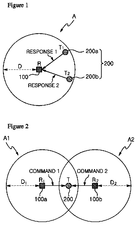
FIGS. 1 to 3 are exemplary diagrams illustrating a collision type situation according to the present invention;
FIG. 4 is a block diagram illustrating the configuration of an RFID interrogator according to the present invention;
FIGS. 5 to 11 are exemplary diagrams referenced for describing the operation of an RFID interrogator according to the present invention;
FIGS. 12 to 14 are flowcharts illustrating an operation flow of an RFID interrogator according to the present invention;
FIG. 15 is a flowchart illustrating a process in which a collision resolution unit retransmits commands for each collision situation according to an embodiment of the present invention;
FIG. 16 illustrates a pseudo code of a collision resolution algorithm described by referring to FIG. 15;
FIGS. 17 to 19 are exemplary timing diagrams for illustrating a collision resolving method depending on each collision situation according to an embodiment of the present invention;
FIG. 20 is a timing diagram for illustrating a meaning of a minimum retransmission wait time according to an embodiment of the present invention;
FIG. 21 is a timing diagram for illustrating a meaning of a maximum retransmission wait time according to an embodiment of the present invention;
FIG. 22 is a timing table in an ISO/IEC 18000-6 Type C environment;
FIG. 23 is a flowchart illustrating a process of dynamically changing a wait time parameter c depending on a current collision percentage; and
FIG. 24 is a flowchart illustrating a process of dynamically changing a wait time parameter c depending on a current collision percentage and a timeout ratio.
Best mode
Hereinafter, preferred embodiments of the present invention will be described with reference to the accompanying drawings in order to help understand the present invention. The embodiments to be described are provided to more easily understand the present invention.
The present invention is not limited to the embodiments.
In a mobile RFID interrogator service in which information on products or works attached with tags are inquired or purchased by means of a mobile phone mounted with an RFID interrogator (RFID reader) operating in an RFID environment, for example, within an ultrahigh frequency (UHF) band, the present invention provides an apparatus and a method that can identify a reason for an occurring collision by analyzing a reception signal having an error so as to solve the occurring error, retransmit a command depending on a collision situation, and properly set a wait time for retransmission in the case in which the error occurs in the received signal due to a collision between the corresponding RFID interrogator and RFID interrogators or tags adjacent thereto.
The present invention relates to an air interface specification of mobile radio frequency identification (RFID). A system according to the present invention, as an ITF (interrogator talks first) system operating in a passive backscatter scheme, includes one or more mobile RFID reader and a plurality of tags. Hereinafter, the RFID reader is described as the RFID interrogator and the two terms have the same meaning as long as they are not differently described or not definitively analyzed.
The RFID interrogator according to the present invention may be not required to support channel sensing. For example, the RFID interrogator does not need to implement Listen Before Talk (LBT) and transmits commands under the risk of colliding with one or more interrogators. Further, the interrogators are not obligated to synchronize by means of a control channel for Time Division Multiplexing (TDM), etc.
Tags are powered by an RF signal provided by the interrogator and respond to an interrogator's command by modulating the reflection coefficient of an antenna, thereby backscattering data to the interrogator. It is assumed that the working mode of the tags is passive and the tags do not actively initiate any kind of RF communication. The present invention relates to collision arbitration and collision avoidance for mobile RFID applications, and more particularly, to mechanisms that aim at mitigating the impact of collisions and are used to avoid follow-up collisions.
Parts that are not specifically covered in the present invention will be sufficiently appreciated in accordance with a radio interface specification published by ISO/IEC 18000-6 Type C and may adopt other radio interface specifications for reference as necessary.
Hereinafter, embodiments of the present invention will be described with reference to the accompanying drawings.
FIGS. 1 to 3 illustrate collision situation of networks according to an embodiment of the present invention.
The collision situation of the networks according to the present invention includes three types such as a `tag on tag collision` that is caused between a plurality of tags, a `multiple interrogators to tag collision` that is caused between a plurality of RFID interrogators and a tag, and an `interrogator to interrogator collision` that is caused between the corresponding RFID interrogator and one or more RFID interrogator adjacent thereto.
First, FIG. 1 illustrates a tag on tag Collision situation according to an embodiment of the present invention.
Referring to FIG. 1, the `Tag on Tag Collision` situation is caused when a plurality of tags 200 are provided in a read range A of one RFID interrogator R 100. In the embodiment of FIG. 1, two tags T1 200a and T2 200b are provided, but the present invention is not limited thereto and two or more tags may be provided.
First, when the R 100 outputs an inventory command, the T1 200a and T2 200b that are located in the A respond to the inventory command of the R 100. At this time, when the T1 200a and T2 200b respond to the inventory command at the same time, parallel responses of the T1 200a and the T2 200b interfere with each other. This is exactly the `tag on tag collision`.
When the `tag on tag collision` occurs, the R 100 has an error when decoding the tag response received from the T1 200a and the T2 200b due to the `tag on tag collision`. Therefore, the R 100 that outputs the inventory command cannot exactly discriminate between the responses of the tags. The `tag on tag collision` can be handled by an anti-collision algorithm described in the radio interface specification (e.g., ISO/IEC 18000-6 Type C). Hereinafter, if there is not provided another description, the tag anti-collision means a known algorithm that resolves the `tag on tag collision`.
Hereinafter, the `tag on tag collision` will be described as a first collision for ease of description.
Meanwhile, FIG. 2 illustrates a multiple interrogators to tag collision situation according to an embodiment of the present invention.
Referring to FIG. 2, a `multiple interrogators to tag collision` situation is caused by a plurality of RFID interrogators. In the embodiment of FIG. 2, two RFID interrogators R1 100a and R2 100b are provided, but the present invention is not limited thereto and two or more RFID interrogators tags may be naturally provided.
That is, in a state when a read range A1 of the R1 100a and a read range A2 of the R2 100b partially overlap each other, a case in which one tag T 200 is positioned in a range where the A1 and the A2 partially overlap each other is described as one example.
At this time, when the R1 100a and the R2 100b output inventory commands to the T 200, the inventory commands outputted from the R1 100a and the R2 100b may collide with each other in the T 200. In this case, the T 200 has an error when decoding the inventory commands received from the R1 100a and the R2 100b.
Hereinafter, the `multiple interrogators to tag collision` will be described as a `second collision` for ease of description.
Meanwhile, FIG. 3 illustrates an `interrogator to interrogator collision` situation according to an embodiment of the present invention.
Referring to FIG. 3, the `interrogator to interrogator collision` includes two RFID interrogators R1 100a and R2 100b and occurs when an interference range B2 of the R2 100b overlaps the read range A1 of the R1 100a. In the embodiment of FIG. 3, the two RFID interrogators are provided, but the present invention is not limited thereto and two or more RFID interrogators may be naturally provided. Herein, the `interrogator to interrogator collision` may occur even when the read ranges of the R1 100a and the R2 100b do not overlap each other.
For example, when the R1 100a outputs the inventory command to the tag T 200 positioned in the range A1, the T 200 transmits a response signal to the inventory command of R1 100a to the R1 100a. Therefore, the R1 100a performs an operation replying to the response signal received from the T 200. At this time, since the A1 and the B2 overlap each other, a predetermined command or other signals outputted from the R2 100b collide with the response signal of the T 200 inputted into the R1 100a. This is exactly the `interrogator to interrogator collision`.
In related art, under a collision between the RFID interrogators, when an error is detected in the response signal received from the T 200, the R1 100a misrecognizes the collision as the `tag on tag collision`, such that the R1 100a intends to resolve the collision by adopting an anti-collision algorithm against the collision.
Further, since the `interrogator to interrogator collision` may occur even when the read ranges of the two RFID interrogators do not overlap each other, a resolution scheme is not disclosed even in the radio interface specification. Therefore, a mechanism used to detect the Interrogator to Interrogator Collision is required in the mobile RFID applications. Therefore, in the embodiment of the present invention to be described below, an embodiment for detecting the `interrogator to interrogator collision` is described.
Hereinafter, the `interrogator to interrogator collision` will be described as a `third collision` for ease of description.
FIG. 4 is a diagram illustrating the configuration of an RFID interrogator according to an embodiment of the present invention.
Referring to FIG. 4, the RFID interrogator according to the present invention includes an interrogator controller 110, an interrogator transmitter 120, an RF communicator 130, an interrogator receiver 140, a collision controller 160, and a timer 150.
The interrogator controller 110 outputs an inventory command to at least one tag that is positioned within a predefined range and processes a tag response received in response to the inventory command.
The interrogator transmitter 120 (modem transmitter) transmits the inventory command of the interrogator controller 110 to the RF communicator 130. Herein, the interrogator transmitter 120 modulates the inventory command outputted from the interrogator controller 110 and transmits the inventory command to the RF communicator 130.
The RF communicator 130 receives the inventory command of the interrogator controller 110 from the interrogator transmitter 120 and transmits the inventory command to at least one tag that is positioned within a predefined range. Further, the RF communicator 130 transmits the inventory command to the outside and receives a signal from the outside during a set receive time. At this time, the RF communicator 130 receives a tag response from a tag within a read range in response to the inventory command which has already been transmitted during the set receive time. Of course, the RF communicator 130 may receive signals of other RFID interrogators or a noise without any signal in addition to the tag response. At this time, the RF communicator 130 transmits the received signal to the interrogator receiver 140.
The interrogator receiver 140 (modem receiver) transmits the received signal from the RF communicator 130 to the interrogator controller 110 and the collision controller 160. At this time, the interrogator receiver 140 transmits data of the received signal to the collision controller 160.
Meanwhile, the interrogator receiver 140 includes a decoder (not shown). At this time, the decoder decodes the received signal from the RF transmitter 130 and detects a valid preamble from the decoded received signal. The interrogator receiver 140 outputs a valid preamble detection (VPD) signal to the collision controller 160 depending on a valid preamble detection result of the decoder.
Further, the decoder detects a cyclic redundancy check (CRC) error from the decoded received signal. The interrogator receiver 140 outputs a CRC error detection signal to the collision controller 160 depending on a CRC error detection result of the decoder.
The collision controller 160 includes a collision diagnosis unit 161 and a collision resolution unit 165.
The collision diagnosis unit 161 checks whether or not a collision occurs with respect to the received signal by analyzing data of the received signal inputted from the interrogator receiver 140 and diagnoses a collision type depending on an analysis result of the data of the received signal.
Herein, the collision diagnosis unit 161 includes a valid bit detection (VBD) module 163 which is a valid bit detection module. The VBD module 163, as a sub-module of the collision diagnosis unit 161, detects a valid bit from the received signal inputted from the interrogator receiver 140. In other words, the VBD module 163 detects a valid logical signal by detecting a rising edge and a falling edge of the received signal, that is, modulated sub-carriers within a tolerance of a radio interface specification. At this time, the VBD module 163 outputs a valid bit detection signal depending on a valid bit detection result.
The collision diagnosis unit 161 determines that the valid bit detection (VBD) signal is positive when the valid bit detection signal is detected. In other words, the collision diagnosis unit 161 determines that a valid bit is detected from the VBD module 163 when the valid bit detection signal is detected.
Meanwhile, the collision diagnosis unit 161 determines that the valid bit detection (VBD) signal is negative when the valid bit detection signal is not detected. In other words, the collision diagnosis unit 161 determines that the valid bit is not detected from the VBD module 163 when the valid bit detection signal is detected.
The collision diagnosis unit 161 determines whether a tag response signal corresponding to a transmitted signal is present on the basis of the valid bit detection signal outputted from the VBD module 163. Therefore, the collision diagnosis unit 161 determines whether the received signal is the tag response corresponding to the transmitted signal or a signal without any signal.
Meanwhile, the collision diagnosis unit 161 further includes an interrogator collision detection (ICD) module 162 which is an interrogator collision detection module that detects a collision of the RFID interrogators. Similar to the VBD module 163, the ICD module 162, a sub-module of the collision diagnosis unit 161, analyzes data of the received signal inputted from the interrogator receiver 140 and calculates an average value with respect to the data of the received signal.
Further, the ICD module 162 detects the collision of the RFID interrogators depending on a comparison result of the average value calculated from the data of the received signal and a registered threshold level. At this time, the ICD module 162 outputs an interrogator collision detection (ICD) signal when the collision of the RFID interrogators is detected.
For example, the ICD module 162 detects that the RFID interrogators collide with each other when the average value calculated from the data of the received signal is equal to or larger than the threshold level. Meanwhile, the ICD module 162 detects that the RFID interrogators do not collide with each other when the average value calculated from the data of the received signal is smaller than the threshold level.
The detailed embodiment thereof will be described with reference to FIGS. 6 and 7.
The collision diagnosis unit 161 can verify whether a collision of the corresponding RFID interrogator and an RFID interrogator adjacent thereto, that is, the third collision occurs on the basis of the interrogator collision detection signal outputted from the ICD module 162. In other words, the collision diagnosis unit 161 determines that the interrogator collision detection (ICD) signal is positive when the interrogator collision detection signal is detected. That is, the collision diagnosis unit 161 determines that the collision of the RFID interrogators is detected from the interrogator collision detection (ICD) module when the interrogator collision detection signal is detected. At this time, the collision diagnosis unit 161 diagnoses when the third collision occurs with respect to the received signal. Meanwhile, the collision diagnosis unit 161 determines that the interrogator collision detection (ICD) signal is negative when the interrogator collision detection signal is not detected. In other words, the collision diagnosis unit 161 determines that the valid bit is not detected from the VBD module 163 when the valid bit detection signal is detected. At this time, the collision diagnosis unit 161 diagnoses when the third collision does not occur with respect to the received signal.
Further, the collision diagnosis unit 161 verifies whether or not a collision of a plurality of adjacent tags, that is, the first collision occurs on the basis of the valid bit detection signal outputted from the VBD module 163 when determining that the interrogator collision detection signal outputted from the ICD module 162 is negative. Further, the collision diagnosis unit 161 can verify whether a collision of a plurality of RFID interrogators and a tag that receives the transmitted signal, that is, the second collision occurs on the basis of the valid bit detection signal outputted from the VBD module 163.
The collision diagnosis unit 161 diagnoses that the first collision occurs with respect to the received signal when determining that the valid bit detection (VBD) signal from the VBD module 163 is positive. The collision diagnosis unit 161 diagnoses that the second collision occurs with respect to the received signal when determining that the valid bit detection (VBD) signal from the VBD module 163 is negative.
The collision diagnosis unit 161 receives the valid preamble detection signal from the interrogator receiver 140 when the valid preamble is detected from the decoder. Further, the collision diagnosis unit 161 receives the CRC error detection signal from the interrogator receiver 140 when the CRC error is detected from the decoder. Herein, the collision diagnosis unit 161 diagnoses a collision type with respect to the received signal on the basis of the valid preamble detection signal and the CRC error detection signal outputted from the interrogator receiver 140.
That is, the collision diagnosis unit 161 can diagnose the collision type with respect to the first collision, the second collision, and the third collision on the basis of the interrogator collision detection signal outputted from the ICD module 162 and the valid bit detection signal outputted from the VBD module 163. The embodiment thereof will be described with reference to Table 1.
TABLE-US-00001 TABLE 1 Collision type Detection First Second Third Signal collision collision collision ICD NEGATIVE NEGATIVE POSITIVE VBD POSITIVE NEGATIVE --
Further, the collision diagnosis unit 161 can diagnose a more specific collision type by further referring to the valid preamble detection signal and the CRC error detection signal inputted from the interrogator receiver 140 in addition to the interrogator collision detection signal outputted from the ICD module 162 and the valid bit detection signal outputted from the VBD module 163. The embodiment thereof will be described with reference to Table 2. Further, the collision diagnosis unit 161 can diagnose a more specific collision type by further referring to the valid preamble detection signal and the CRC error detection signal inputted from the interrogator receiver 140 in addition to the interrogator collision detection signal outputted from the ICD module 162 and the valid bit detection signal outputted from the VBD module 163. The embodiment thereof will be described with reference to Table 2.
TABLE-US-00002 TABLE 2 Collision type Detection signal First collision Second collision Third collision ICD NEGATIVE NEGATIVE POSITIVE VBD POSITIVE NEGATIVE -- VPD POSITIVE NEGATIVE NEGATIVE POSITIVE NEGATIVE CRC ERROR POSITIVE -- -- POSITIVE --
When the above-mentioned condition is satisfied, the collision diagnosis unit 161 determines the collision situation to diagnose any one collision type among the first collision, the second collision, and the third collision and when the above-mentioned condition is not satisfied, the collision diagnosis unit 161 determines when the collision does not occur in the received signal.
At this time, the collision diagnosis unit 161 transfers a collision diagnosis result to the collision resolution unit 165. Herein, the collision diagnosis result includes occurrence of the collision or not and when the collision occurs, the collision diagnosis result includes information on the collision type.
The collision resolution unit 165 performs an operation corresponding to the collision diagnosis result applied from the collision diagnosis unit 161. In other words, when the collision diagnosis unit 161 diagnoses that the collision does not occur, the collision resolution unit 165 reports the diagnosis result to the interrogator controller 110. Further, when any one among the tag on tag collision, the multiple interrogators to tag collision, and the interrogator to interrogator collision occurs, the collision resolution unit 165 resolves the collision problem by performing a collision resolution algorithm corresponding to each collision type. The collision resolution unit 165 includes a situational command retransmission portion 1651 that determines whether or not the command is retransmitted based on the occurrence of the collision or not and the collision type and a random wait time calculating unit 1652 that calculates a random wait time for retransmitting the command. The detailed operation of the collision resolution unit 165 will be described after the collision diagnosis unit 161's collision diagnosis operation is described.
FIG. 5 is a diagram referenced for describing the operation of the collision controller according to the present invention.
Referring to FIG. 5, the collision diagnosis unit 161 receives received signal data I1 from the interrogator receiver 140. At this time, the VBD module 163 of the collision diagnosis unit 161 outputs a valid bit detection signal I11 by detecting the valid bit from the received signal data. Further, the ICD module 162 of the collision diagnosis unit 161 outputs an interrogator collision detection signal I12 by detecting the interrogator collision from the received signal data.
Meanwhile, the collision diagnosis unit 161 receives a valid preamble detection signal I2 and a CRC error detection signal I3 from the interrogator receiver 140.
Further, the collision diagnosis unit 161 receives time information I4 from the timer 150. At this time, the collision diagnosis unit 161 counts the time until a received time set with respect to the transmitted signal is timed out on the basis of the time information I4 provided from the timer 150. Further, the collision diagnosis unit 161 counts the time until a tag response corresponding to the transmitted signal is received.
The collision diagnosis unit 161 diagnoses the occurrence of the collision or not and the occurring collision type with respect to the received signal by using information on the valid bit detection signal I11, the interrogator collision detection signal I12, the valid preamble detection signal I2, and the CRC error detection signal I3.
At this time, the collision diagnosis unit 161 outputs the collision diagnosis result to the collision resolution unit 165. Herein, the collision diagnosis result includes information of no collision detected, the first collision, the second collision, and the third collision. Of course, the collision diagnosis result may include the collision control command for resolving the diagnosed collision.
FIGS. 6 and 7 are diagrams referenced for describing the operation to detect the ICD in the ICD module of the collision diagnosis unit.
The collision diagnosis unit 161 adjusts a parameter value of the ICD module 162 before detecting the ICD signal.
For example, the collision diagnosis unit 161 determines a window (or tap) size of a moving average filter (MAF) from a link frequency (LF), a data rate, a signal modulation type, etc. Herein, it is possible to manually or automatically adjust the size of the window which is a section where an average value for the received signal data is calculated.
The collision diagnosis unit 161 determines a tag response cycle for receiving the tag response to the transmitted signal. Herein, the tag response cycle is determined from the link frequency, the data rate, the modulation type, etc.
Further, the collision diagnosis unit 161 determines a threshold level which is a reference for detecting the interrogator signal in the ICD module 162. Herein, the threshold level is determined by at least one of the signal modulation type, the link frequency (LF), the data rate, etc.
As described above, after the parameter value of the ICD module 162 is determined by the collision diagnosis unit 161, the ICD module 162 checks whether or not the RFID interrogators collide with each other with respect to symbol data of the received signal inputted from the interrogator receiver 140.
FIG. 6 is an exemplary diagram illustrating the configuration of the ICD module according to the present invention and FIG. 7 illustrates a flow of a signal in the ICD module. Referring to FIGS. 6 and 7, the ICD module 162 includes an average calculation unit 162a and a comparator 162b.
The average calculating unit 162a receives the received signal data inputted from the interrogator receiver 140 as an input value and calculates an average value for the inputted received signal data. At this time, the average calculation unit 162a includes the moving average filter (MAF). That is, when the received signal data is inputted into the moving average filter, the average calculation unit 162a calculates the average value by summing up filter values (S1, S2, S3, . . . , Sn) inputted into a window of the moving average filter. That is, the average value of the section inputted into the window of the moving average filter is calculated. If the received signal data is additionally inputted into the window of the moving average filter, an average value for the additionally inputted received signal data is calculated.
The comparator 162b outputs the interrogator collision detection signal by comparing the average value calculated from the average calculation unit 162a and the threshold level. At this time, the comparator 162b outputs the interrogator collision detection signal for an average value that is equal to or larger than the threshold level among the average values calculated from the average calculation unit 162a. At this time, the collision diagnosis unit 160 regards that the corresponding interrogator collision detection signal, that is, the ICD is positive.
That is, the collision diagnosis unit 161 considers that the third collision occurs between the corresponding RFID interrogator and the RFID interrogator adjacent thereto when the ICD is positive in the interrogator collision detection signal. At this time, the value of the ICD indicates interrogators that collide with each other.
In other words, in the case in which the symbol data of the received data is inputted as shown in FIG. 7(a), the average value of the moving average filter section for the received signal data inputted during the tag response time T1 determined by the collision diagnosis unit 160 is shown in FIG. 7(b). Herein, the collision diagnosis unit 160 receives the received signal from the RF communicator 130 during a set receive time after transmitting the transmitted signal. In the embodiment, the collision diagnosis unit 160 receives the received signal during the tag response time T1.
At this time, the ICD module 162 compares the average values of (b) with the threshold level previously determined by the collision diagnosis unit 161. As a result, the ICD module 162 outputs the interrogator collision detection signal to the collision diagnosis unit 161 as shown in FIG. 7(c). That is, it can be verified that the ICD is positive at `T2` which is a region which is larger than the threshold value among the average values during `T1` which is the tag response time.
Therefore, the collision diagnosis unit 161 determines that the third collision occurs in the received signal on the basis of the interrogator collision detection signal outputted from the ICD module 162.
FIG. 8 illustrates an embodiment that detects the valid bit in the VBD module. In particular, FIG. 8 illustrates an example in which the valid bit is detected in a received signal encoded by Miller-4.
Herein, when the valid bit is detected by the VBD module 163, the VBD is `positive` and when the valid bit is not detected, the VBD is `negative`. The VBD module 163 outputs the valid bit detection signal depending on the valid bit detection result. Therefore, the collision diagnosis unit 161 diagnoses the collision type of the received signal on the basis of the valid bit detection signal outputted from the VBD module 163.
Accordingly, the collision diagnosis unit 161 can diagnose the collision types of FIGS. 9 to 11 from the previously obtained information, that is, the interrogator collision detection signal, the valid bit detection signal, the valid preamble detection signal, and the CRC error detection signal.
First, FIG. 9 illustrates a first collision situation and more particularly, illustrates commands and response signals that are transmitted and received between the RFID interrogator R and a tag 1 T1 and a tag 2 T2. However, a state in which interferences of other RFID interrogators are not detected is considered.
First, when the RFID interrogator R transmits the commands to the tag 1 T1 and the tag 2 T2, the tag 1 T1 and the tag 2 T2 transmit a response 1 and a response 2 to the RFID interrogator R, respectively. At this time, parts of two or more tag responses, that is, the response 1 and the response 2 overlap each other, such that the collision occurs.
At this time, the collision diagnosis unit 161 diagnoses that the first collision occurs when the following <Condition A> or <Condition B> is satisfied.
<Condition A>
1) Valid preamble detected (VPD is positive)
2) CRC error is detected.
3) Valid bit detected (VBD is positive)
4) No interrogator collision detected (ICD is negative)
<Condition B>
1) No Valid preamble detected (VPD is negative)
2) Valid bit detected (VBD is positive)
3) No interrogator collision detected (ICD is negative)
In other words, like <Condition A>, when the conditions that the VPD is `positive` from the valid preamble detection signal, the CRC error is detected, the VBD is `positive` from the valid bit detection signal, and the ICD is `negative` from the interrogator collision detection signal are satisfied, the collision diagnosis unit 161 diagnoses that the first collision occurs in the received signal. Meanwhile, like <Condition B>, when the conditions that the VPD is `negative`, the VBD is positive, and the ICD is `negative` are satisfied, the collision diagnosis unit 161 diagnoses that the first collision occurs in the received signal.
Accordingly, the collision diagnosis unit 161 outputs the collision diagnosis result including first collision information to the collision resolution unit 165 when any one of <Condition A> and <Condition B> is satisfied.
FIG. 10 illustrates a second collision situation and more particularly, illustrates commands and response signals that are transmitted and received between an interrogator 1 and an interrogator 2 and one tag.
The description continues in the full USPTO document.
 Lapsed, fee not paid8 drawings