Background of the invention
Renal dysfunction or failure and, in particular, end-stage renal disease, causes the body to lose the ability to remove water and minerals and excrete harmful metabolites, maintain acid-base balance, and control electrolyte and mineral concentrations within physiological ranges. Toxic uremic waste metabolites including urea, creatinine, uric acid, and phosphorus accumulate in the body's tissues, which can result in a person's death if the filtration function of the kidney is not replaced.
Dialysis is commonly used to replace kidney function by removing these waste toxins and excess water. In one type of dialysis treatment, hemodialysis, toxins are removed from a patient's blood externally in a hemodialysis machine. Blood passes from the patient through a dialyzer separated by a semi-permeable membrane from an externally-supplied dialysate. Waste and toxins dialyze out of the blood through the semi-permeable membrane into the dialysate, which is then discarded. Hemodialysis treatment typically lasts several hours and must be performed under medical supervision three or four times a week, requirements that significantly decrease a patient's autonomy and quality of life. Also, since hemodialysis is performed periodically instead of continuously, the patient's condition and general well-being tend to be poor both immediately before hemodialysis (when toxin levels are high) and after hemodialysis (when electrolytes are imbalanced), resulting in the patient having symptoms that range from nausea and vomiting to edema.
Peritoneal dialysis is another type of dialysis treatment used to replace kidney function in which sterile, pyrogen-free dialysis solution is infused into the patient's peritoneal cavity. The peritoneal membrane serves as a natural dialyzer and toxic uremic waste metabolites and various ions diffuse from the patient's bloodstream across the membrane into the dialysis solution due to their concentration gradients. At the same time, water is drawn into the peritoneal cavity by an osmotic gradient. The dialysis solution is removed, discarded and replaced with fresh dialysis solution on a semi-continuous or continuous basis. Draining, discarding and replacing the large volumes of solution needed for peritoneal dialysis is still inconvenient, unwieldy and expensive, especially for peritoneal dialysis treatment at home instead of at a treatment center.
To address this problem, devices have been designed that reconstitute used dialysate from hemodialysis and/or peritoneal dialysis solution as opposed to discarding it. The dialysate can be regenerated in a machine employing a device that eliminates urea from the solution. For example, the original REDY.RTM. (REcirculating DYalysis) Sorbent System (Blumenkrantz et al., Artif. Organs 3(3):230-236, 1978) consists of a sorbent cartridge having five layers through which dialysate solution containing uremic waste metabolites flows in order to be regenerated. The spent dialysate flows through a purification layer that removes heavy metals (e.g., copper and lead) and oxidants (e.g., chlorine and chloramine), an aluminum oxide layer containing urease bound to some of the aluminum oxide which degrades the urea in the dialysate into ammonia and carbon dioxide gas (in equilibrium with ammonium carbonate), a zirconium phosphate layer that adsorbs the ammonium ions produced from urea degradation along with other cations (e.g., sodium, potassium, magnesium and calcium), a hydrated zirconium oxide layer that binds phosphate and other anions (e.g., fluoride and sulfate) in exchange for acetate, and an activated carbon layer that adsorbs other organic compounds (e.g., creatinine and uric acid).
Typically, the sorbents used in devices such as the REDY.RTM. Sorbent System adsorb not only the urea degradation products, but also essential ions such as, for example, calcium and magnesium that have diffused into the dialysate. These ions must then be replaced in the patient. Typically, current sorbent-based hemodialysis machines replace these essential ions continuously using an extra pump and associated valve and control mechanisms, devices that increase the weight and complexity of a hemodialysis machine, and would present similar problems for a peritoneal dialysis system.
There is, therefore, a need for a dialysis device that is more convenient, safe and effective and that significantly improves a patient's quality of life over current devices and methods.
Summary of the invention
The present invention provides a portable peritoneal dialysis device that can be comfortably worn or carried by a patient and which can operate continuously or semi-continuously during periods of dialysis to clear uremic waste metabolites from a patient with renal dysfunction or failure, without overly depleting the patient's body of essential ions, such as, for example, calcium and magnesium.
A portable peritoneal dialysis system of this invention can include an inlet port for providing inflow to the patient's peritoneal cavity, an outlet port for providing outflow from the patient's peritoneal cavity, and a volume of dialysate for flow into and out of the patient's peritoneal cavity, thereby removing from the dialysate uremic waste metabolites that have diffused into the dialysate. This portable peritoneal dialysis system can also include a closed liquid flow loop, including a pump, for flowing the dialysate into and out of the patient's peritoneal cavity, and an organic- and phosphate-removing stage, including at least one replaceable cartridge in the closed liquid flow loop, the cartridge containing material for removing organic compounds and phosphate from dialysate removed from the patient's peritoneal cavity. In one embodiment, this material is packed around semi-permeable hollow fibers. This portable peritoneal dialysis system can further include a urea- and ammonia-removing stage, including at least one replaceable cartridge in the closed liquid flow loop, the cartridge containing material for removing urea and ammonia from dialysate removed from the patient's peritoneal cavity, the material being packed around semi-permeable hollow fibers with interior fiber walls that reject cations, thereby retaining cations in the dialysate. In another embodiment, the material in the cartridge for removing organic compounds and phosphate can include a mixture of activated carbon and zirconium oxide. In yet another embodiment, the material in the cartridge for removing urea and ammonia can include urease and strong acid cation exchange resin or sorbent, such as an ion exchange sorbent. In one embodiment, the urease can be in the form of cross-linked jack bean meal polyethylenimine-carbon composite. In another embodiment, the portable peritoneal dialysis system can further include an ammonia-removing stage, including at least one replaceable cartridge in the closed liquid flow loop, the cartridge containing material for removing ammonia from dialysate removed from the patient's peritoneal cavity, the material being packed around hollow fibers with interior fiber walls that reject cations, thereby retaining cations in the dialysate. In one embodiment, the semi-permeable hollow fibers with interior fiber walls that reject cations can reject calcium, magnesium, potassium, and sodium cations. In another embodiment, the material in the cartridge for removing ammonia can include strong acid cation exchange resin or sorbents, including ion exchange sorbents. In yet another embodiment, the portable peritoneal dialysis system can further include an organic- and phosphate-removing and pH-control stage, including at least one replaceable cartridge in the closed liquid flow loop, the cartridge containing material for removing organic compounds from dialysate removed from the patient's peritoneal cavity and material for controlling the pH of the dialysate at or near physiological pH. In one embodiment, the material in the cartridge for removing organic compounds can include activated carbon, and the material in the cartridge for controlling the pH of the dialysate can include a mixture of zirconium oxide and sodium zirconium carbonate.
In another embodiment, the portable peritoneal dialysis system can be configured as a belt adapted to be worn by the patient, wherein each cartridge of each stage is substantially rectangular and sufficiently small to be concealable under a patient's clothing. In another embodiment, the portable peritoneal dialysis system can be configured as an integrated loop adapted to be worn by a patient as a belt or docked into a tabletop docking unit. In yet another embodiment, the portable peritoneal dialysis system can be configured as a tabletop unit.
The invention is also directed to a method for providing peritoneal dialysis to a patient using a portable peritoneal dialysis system including a closed liquid flow loop for flowing a volume of dialysate into and out of the patient's peritoneal cavity and through dialysate regenerating stages. The method includes flowing a volume of dialysate from the patient's peritoneal cavity through an organic- and phosphate-removing stage, including at least one replaceable cartridge in the closed liquid flow loop, the cartridge containing material for removing organic compounds and phosphate from dialysate removed from the patient's peritoneal cavity. Thereafter, the method further includes flowing the volume of dialysate through semi-permeable hollow fibers contained in a urea- and ammonia-removing stage, including at least one replaceable cartridge in the closed liquid flow loop, the cartridge containing material for removing urea and ammonia from dialysate removed from the patient's peritoneal cavity, the material being packed around the semi-permeable hollow fibers, the semi-permeable hollow fibers having interior fiber walls that reject cations, thereby retaining cations in the dialysate while removing from the dialysate uremic waste metabolites that have diffused into the dialysate, to produce regenerated dialysate, and introducing the regenerated dialysate into the patient's peritoneal cavity.
Unlike dialysis systems to date, the portable peritoneal dialysis system of the invention provides for a dialysis device that can allow the patient to maintain a more normal, active lifestyle. Due to the regeneration of the peritoneal dialysis solution, a relatively small volume of dialysate needs to be circulated in the portable peritoneal dialysis system, which allows the system to be relatively small and lightweight and thus comfortable to wear or carry. As the portable peritoneal dialysis system is able to operate continuously or semi-continuously during periods of dialysis through regeneration of the dialysate, it improves a patient's overall well-being and quality of life, freeing the patient from dialysis systems that are labor-intensive, time-consuming and/or require medical supervision. Moreover, the portable peritoneal dialysis system regenerates the dialysate without removing certain essential ions from the dialysate and, ultimately, from the patient's body. This is most advantageous as, currently, equipment to replace these essential ions generally includes an extra pump that increases the weight and complexity of a portable peritoneal dialysis system.
Brief description of the drawings
The foregoing will be apparent from the following more particular description of preferred embodiments of the invention, as illustrated in the accompanying drawings in which like reference characters refer to the same parts throughout the different views. The drawings are not necessarily to scale, emphasis instead being placed upon illustrating embodiments of the present invention.
FIG. 1 is a schematic illustration of a portable peritoneal dialysis system according to this invention.
FIG. 2 is a graph of phosphorus concentration as a function of time in a test of phosphorus removal by 3.6 grams of zirconium oxide, 6.2 grams of activated carbon, and a mixture of 3.6 g of zirconium oxide and 6.2 g of activated carbon from a 2 liter volume of solution containing 1.10 grams of sodium phosphate dihydrate and 0.40 grams of anhydrous creatinine.
FIG. 3 is a schematic illustration of a first cleaning stage of a portable peritoneal dialysis system according to this invention.
FIG. 4 is a graph of phosphorus concentration as a function of time in a test of phosphorus and creatinine removal by a first stage cartridge from a solution containing 8.0 mg/dL of phosphorus and 12 mg/dL of creatinine.
FIG. 5 is a graph of creatinine concentration as a function of time in a test of phosphorus and creatinine removal by a first stage cartridge from a solution containing 8.0 mg/dL of phosphorus and 12 mg/dL of creatinine.
FIG. 6 is a schematic illustration of a second cleaning stage of a portable peritoneal dialysis system according to this invention.
FIG. 7 is an exploded partial cross-sectional view of the interior of the second cleaning stage of a portable peritoneal dialysis system illustrated in FIG. 6.
FIG. 8 is a graph of blood urea nitrogen (BUN) concentration as a function of time in a test of urea and ammonia removal by a second stage cartridge containing 141 g of zirconium phosphate and 5 g of immobilized urease composite.
FIG. 9 is a graph of ammonia concentration as a function of time in a test of urea and ammonia removal by a second stage cartridge containing 141 g of zirconium phosphate and 5 g of immobilized urease composite.
FIG. 10 is a graph of blood urea nitrogen (BUN) concentration as a function of time in a test of urea and ammonia removal by a second stage cartridge containing 132 g of zirconium phosphate and 5 g of immobilized urease composite.
FIG. 11 is a graph of ammonia concentration as a function of time in a test of urea and ammonia removal by a second stage cartridge containing 132 g of zirconium phosphate and 5 g of immobilized urease composite.
FIG. 12 is a graph of blood urea nitrogen (BUN) concentration as a function of time in a test of urea and cation transport across thin film composite membrane hollow fibers of a second stage cartridge.
FIG. 13 is a graph of calcium (Ca.sup.+2) concentration as a function of time in a test of urea and cation transport across thin film composite membrane hollow fibers of a second stage cartridge,
FIG. 14 is a graph of potassium (K.sup.+) concentration as a function of time in a test of urea and cation transport across thin film composite membrane hollow fibers of a second stage cartridge.
FIG. 15 is a graph of sodium (Na.sup.+) concentration as a function of time in a test of urea and cation transport across thin film composite membrane hollow fibers of a second stage cartridge,
FIG. 16 is a schematic illustration of a third cleaning stage of a portable peritoneal dialysis system according to this invention.
FIG. 17 is schematic illustration of a fourth cleaning stage of a portable peritoneal dialysis system according to this invention.
FIG. 18 is a schematic flow diagram of one embodiment of the portable peritoneal dialysis system according to this invention.
FIG. 19 is a photograph of a cartridge shell of a "racetrack" design for a cleaning stage.
FIG. 20 is a photograph of an embodiment of the portable peritoneal dialysis system in a belt configuration.
FIG. 21 is a schematic illustration of an embodiment of the portable peritoneal dialysis system in a belt configuration.
FIG. 22 is an illustration of an embodiment of the portable peritoneal dialysis system in an integrated loop configuration.
FIG. 23 is an illustration of an embodiment of the integrated loop illustrated in FIG. 22 in a belt configuration.
FIG. 24 is an illustration of an embodiment of the integrated loop illustrated in FIG. 22 in a tabletop docking unit configuration.
FIG. 25 is an illustration of an embodiment of the integrated loop illustrated in
FIG. 22 in an angled tabletop docking unit configuration.
FIG. 26 is an illustration of an embodiment of the portable peritoneal dialysis system in a tabletop configuration.
Detailed description of the invention
The present invention generally relates to a portable peritoneal dialysis system that removes uremic waste metabolites from a patient suffering from a disorder associated with the accumulation of uremic toxins (e.g., chronic kidney failure). The system can be used to treat a disorder such as, for example, renal disease, including early renal disease, renal dysfunction or renal failure (e.g., end stage renal disease). As used herein, the terms "uremic waste metabolites" and "uremic solutes" refer to compounds, such as those containing nitrogen, produced by the body as waste products and includes compounds like urea, uric acid, creatinine, phosphorus, and .beta.-2-microglobulin, and other materials. See Vanholder R. et al., Kidney International 63:1934-1943, (2003). Renal failure or dysfunction leads to uremic toxicity, which occurs when the levels of uremic waste metabolites in a patient are elevated compared to the levels of the toxins in individuals with normal renal function.
Thus, the present invention relates to a portable peritoneal dialysis system that, unlike previous systems and devices, can be small enough in size to be wearable or portable without significant burden to a patient. The peritoneal dialysis can be performed continuously or semi-continuously, as the peritoneal dialysis system contains cleaning stages that each include one or more replaceable cartridges that regenerate the dialysate that is then circulated in the system. An example of desired amounts for daily removal of uremic solutes from a typical patient by a portable peritoneal dialysis (PD) system, while maintaining physiological pH of about 7.4 of the dialysate, are listed in Table 1. As indicated in Table 1, the maximum desired amounts are, for example, removal from a patient that has missed a treatment, or has a substantially larger muscle mass than a typical patient, or is particularly non-compliant with dietary restrictions.
TABLE-US-00001 TABLE 1 An Example of a Desired Daily Uremic Solute Removal Requirements for Portable PD System Desired Removal Quantity Maximum Desired Substance to be removed per day (average) Removal Quantity per day Urea 20 grams 40 grams Phosphorus 800 milligrams 1300 milligrams Sulfate 4.5 grams 8 grams Uric Acid 400 milligrams 600 milligrams .beta.-2-microglobulin 300 micrograms 300 milligrams Creatinine 750 milligrams 2500 milligrams
In one embodiment, the portable peritoneal dialysis system can include several stages for cleaning the dialysate, for example two, three, four or more stages, connected in series. In a preferred embodiment, each cleaning stage is achieved by one or more cartridges. The cartridges can be worn or carried by a patient, either on the person, or in a tabletop configuration. In another preferred embodiment, all stages can be small enough to be worn comfortably by a patient in a belt configuration that, preferably, can be concealed under clothing. A pump, such as a battery operated pump, also preferably attached to the belt, circulates the dialysate through each cartridge in a closed loop that includes the patient's peritoneal cavity. In a preferred embodiment, the pump can include a disposable cassette, or a disposable pump head, that integrates with the cleaning stages to form an integrated loop. A disposable cassette or pump head serves to isolate the pump mechanism from the dialysate, enabling the reuse of the pump without the necessity of cleaning and sterilizing the mechanism. Each cleaning stage can perform one or more functions in regenerating the dialysate. One or more identical cartridges can be connected in series, or, alternatively, connected in parallel, for patients that require the removal of larger amounts of uremic solutes. One or more spent cartridges can be replaced by the patient as needed. In a preferred embodiment, the integrated loop can be replaced daily.
FIG. 1 illustrates a specific preferred embodiment of a portable peritoneal dialysis system according to this invention. Each of the components will be described in more detail in the description of each cleaning stage.
A first cleaning stage containing activated carbon and zirconium oxide surrounding semi-permeable fibers can be used to remove organic compounds, phosphorus and/or phosphate, and sulfate. Organic compounds can include, for example, creatinine, p-cresol sulfate, uric acid, and .beta.-2-microglobulin. Organic compounds are usually removed using activated carbon, typically charcoal. Preferably, the activated carbon has a large surface area per unit volume, a wide range of pore sizes for adsorbing various size uremic toxins, and a high purity and/or USP grade. High purity of the carbon can be achieved through multiple acid and/or water washes to remove any water soluble impurities. It is also advantageous for the carbon to be in the form of small granules or a coarse powder for optimal distribution around the fibers and optimal solute transport. Examples of appropriate activated carbon include: Nuchar.RTM. Aquaguard 40 (MeadWestvaco, Glen Allen, Va.), Norit.RTM. ROX, and Norit.RTM. E Supra (Norit Americas, Marshall, Tex.). A preferred activated carbon is acid-washed pyrolyzed coal-derived activated carbon, such as that marketed by Calgon Carbon Corporation, Pittsburgh, Pa.
Phosphorus, as phosphate (PO.sub.4.sup.3-, HPO.sub.4.sup.2-, and H.sub.2PO.sub.4.sup.-), and sulfate (SO.sub.4.sup.2-) can be removed by binding to anion exchange resins, or to hydrous zirconium oxide (HZO). Appropriate anion exchange resins include DOWEX.TM. 1 (hydroxide form), M-43, 21 K XLT, Marathon.TM. MSA, and M4195 (copper form) (Dow Chemical, Midland, Mich.), and Amberlite.TM. 96 (Rohm and Haas, Philadelphia, Pa.). In a preferred embodiment, hydrous zirconium oxide (e.g., zirconium oxide in the acetate or carbonate counter ion form) can be used to bind phosphate and sulfate. In a more preferred embodiment, the activated carbon powder can be mixed with the hydrous zirconium oxide powder prior to loading the mixture into the first cartridge. A comparison of phosphorus removal using a mixture of 6.2 grams of activated carbon powder and 3.6 grams of hydrous zirconium oxide, as compared to the same amounts of the separate components was performed, wherein a 2 liter volume solution containing 1.10 grams of trisodium phosphate dihydrate and 0.40 grams of anhydrous creatinine was mixed. The solution was pumped through the hollow fibers of a first stage cartridge at 100 ml/min (milliliters per minute). Samples were removed periodically and analyzed. As illustrated in FIG. 2, hydrous zirconium oxide retains its ability to bind phosphate when mixed with activated carbon.
For efficient uremic solute removal and dialysate transport through the cartridge, the mixture of activated carbon and hydrous zirconium oxide powders can be packed around hollow fibers designed for high rates of diffusive and convective transport of uremic solutes through pores in the fiber walls, and for low resistance to the flow of dialysate through the inside (lumen side) of the hollow fibers. Appropriate hollow fiber materials include cellulose, nylon, polyvinylidene fluoride, polysulfone, polyether sulfone, and polypropylene. A preferred embodiment can include polysulfone hollow fibers with an inner diameter equal to or less than about 210 .mu.m (micrometers), a wall thickness equal to or less than about 40 .mu.m, and an ultrafiltration molecular weight cutoff of about 100 kDa (kilo Daltons), such as, for example, the Optiflux 180 dialyzer (Fresenius Medical Care North America, Waltham, Mass.).
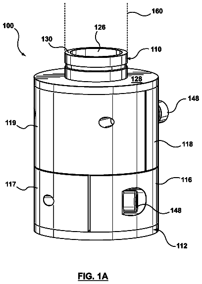
One embodiment of a first stage is illustrated in FIG. 3. Therein, first stage cartridge 100 can include about 4500 hollow fibers 110, of which four fibers are illustrated. The mixture 120 of activated carbon and hydrous zirconium oxide powders is packed around the fibers 110. In a preferred embodiment, the hollow fibers are made of polysulfone, configured to flow at least about 100 ml/min of dialysate with a maximum resulting pressure buildup of about 10 mmHg. The total volume occupied by 4500 polysulfone fibers, excluding potted ends, is about 15-30 cc (cubic centimeters), more preferably about 18 cc, for a total membrane area of 0.21 m.sup.2 (square meters). A mixture of about 40-80 g, preferably about 60 g of hydrous zirconium oxide (acetate counter-ion form) and about 30-55 g, preferably about 44 g of activated carbon is mixed uniformly and packed around the polysulfone fibers. The dialysate flows into the inside (lumen side) of fibers 110, and the organic compounds, phosphate, and sulfate pass through the pores of the fibers and are adsorbed on the shell side by the mixture 120 of activated carbon and hydrous zirconium oxide. Any gases displaced by fluid on the shell side are expelled to the atmosphere through hydrophobic vents 130. A hydrophobic vent (e.g., D30480, W. L. Gore & Associates, Newark, Del.) allows gases to pass through but not aqueous liquids. The partially cleaned dialysate then flows out of cartridge 100 to the next cleaning stage. A test of phosphorus and creatinine removal in the first stage was performed, wherein an 8 liter volume solution containing 7.39 grams of Na.sub.2HPO.sub.4.12H.sub.2O and 0.96 grams of anhydrous creatinine was mixed. The mixture was designed to produce a concentration of 8.0 mg/dL (milligrams per deciliter) of phosphorus and 12 mg/dL of creatinine. The solution was pumped through the hollow fibers of a first stage cartridge at 100 ml/minute. Samples were removed periodically and analyzed. The results for phosphorus and creatinine concentrations as a function of time are illustrated in FIGS. 4 and 5, respectively.
A second cleaning stage can be used to remove urea from the dialysate. Urea can be removed by adsorption onto a strong acid cation exchange resin or onto a sorbent, including an ion exchange sorbent, or by initially breaking down the urea into ammonia and carbon dioxide gas with a urea-degrading enzyme followed by removal of the ammonia byproduct by adsorption onto the strong acid cation exchange resin or the sorbent, and venting of the carbon dioxide to the atmosphere. The urea-degrading enzyme can be naturally occurring (e.g., urease from jack beans, other seeds or bacteria), or produced by recombinant technology (e.g., in bacterial, fungal, insect, or mammalian cells that express and/or secrete urea-degrading enzymes), or produced synthetically (e.g., synthesized).
In one embodiment, immobilizing the urease is generally preferred, because immobilization stabilizes the urease while retaining its enzymatic activity, and reduces the likelihood of the urease becoming entrained in the dialysate stream and producing ammonia downstream of the cartridge, away from the ammonia sorbent. Urease can be immobilized by binding it to aluminum oxide, (e.g., SORB, HISORB, Sorb Technology), or to a resin, such as, for example, Amberzyme.TM. (Rohm and Haas). The enzyme (e.g., urease) may also be chemically attached to the membrane or, alternatively, to porous beads or a resin. This attachment both stabilizes the enzyme for extended use and, in the case of attachment to porous beads or resin, allows the urease to be filled and/or replaced in the device. In particular, urease can be chemically attached to the exterior of the polysulfone hollow fiber membrane or to separate fibers or resins. Attachment can be through reactive pendant groups of amino acid portions of the enzyme such as thiol groups, amino groups, or carboxylic acid groups that will not significantly affect the catalytic site. Chemistries that can be used to immobilize enzymes or cross-linked enzyme crystals (CLECs) are well-known in the art (see e.g., J. Jegan Roy and T. Emilia Abraham, Strategies in Making Cross-Linked Enzyme Crystals, Chemical Reviews, 104(9):3705-3721 (2004)). In addition, urease can be used in its crystallized form and be mixed with the ion exchange resin or sorbent, for example, for degradation of the urea. In a preferred embodiment, urease enzyme derived from jack bean meal can be immobilized by cross-linking with polyethylenimine-carbon composite, as described in U.S. application Ser. No. 12/552,332, filed on Sep. 2, 2009.
The ammonia produced in the enzymatic breakdown of urea can be toxic to humans in high concentrations (e.g., above about 2000 .mu.g/dL (micrograms/deciliter)), and also alters the pH away from the physiological pH, inhibiting the enzymatic activity of urease. Therefore, ammonia needs to be removed, and can be removed either by adsorption onto polymeric strong acid cation exchange resins, such as, for example, sulfonic acid substituted polystyrene cross-linked with divinyl benzene, or onto an ion exchange sorbent, such as, for example, zirconium phosphate. Any strong acid cation exchange resin with sufficient ammonia (ammonium ion) binding capacity and purity is suitable. Specific examples of strong acid cation exchange resin include Amberlite.TM. IRN 77, IRN 97, IRN 99, IR 120, UP 252, CG 15, CG 120, IRC 50, IR 200, and IRA 900 (Rohm and Haas, Philadelphia, Pa.), or comparable resins manufactured by Dow Chemical, Mitsubishi, Purolite, Sybron, and Lanxess.
In a preferred embodiment, the ammonia can be removed by adsorption onto zirconium phosphate. In a more preferred embodiment, zirconium phosphate with improved ammonia binding capacity is prepared as described in U.S. application Ser. No. 12/569,485. An advantageous property of zirconium phosphate is that it helps control the pH in the vicinity of the urease, maintaining it at or near physiological pH, and therefore maintaining the enzymatic activity of the urease.
Polymeric strong acid cation exchange resins or ion exchange sorbents bind ammonia in the form of ammonium ion (NH.sub.4.sup.+), and the ability of the resin or sorbent to bind ammonium ion is reduced by competition for binding sites from other positively charged ions (cations), thus requiring larger amounts of ammonia-removing resins or sorbents, and increasing the weight of the cartridge. Therefore, it is preferable to exclude cations other than ammonium ion from the portion of the cartridge that contains the urease and cation exchange resin or zirconium phosphate sorbent. Cation retention in the dialysate has the additional benefit that the patient's system is not overly depleted of essential ions, such as, for example, calcium (Ca.sup.+2) and magnesium (Mg.sup.+2).
A preferred approach to cation retention in the dialysate can be to employ hollow fibers that have walls which allow urea to pass through but not significant concentrations of cations. Hollow fibers can be fabricated from or coated with a cation-rejecting material. For example, a layer can be formed on the inside or outside of the hollow fibers by coating or co-extruding them with a cation-rejecting material. The material forming the selective cation-rejecting layer can be, for example, esterified cellulose or acetylcellulose (cellulose acetate). In a preferred embodiment, the selective layer can be acetylcellulose, as described in German Application No. DE 10 2008 003 090.2, filed on Jan. 3, 2008, and published as WO 2009/083260 Al on Jul. 9, 2009. As disclosed in that application, hollow fibers were produced by the phase inversion process. First, two spinning dope solutions A and B were produced. The first spinning dope solution A comprised the material for the lumen-side selection layer of the hollow fiber membrane and the second spinning dope solution B comprised the material for the support layer.
The spinning dope solution for the support layer (the outer layer) consisted of 20% by weight of Udel 3500 polysulphone and 5% by weight of K90 polyvinylpyrrolidone and also 1% by weight of water, which were in solution in dimethylacetamide. The viscosity of this solution was about 11 500 mPas. The spinning dope for the lumen-side selection layer consisted of 30% by weight of cellulose diacetate having a molecular weight of 29 kD (kilo Dalton) and an acetyl content of 40% (available from Sigma/Aldrich). It was dissolved in dimethylacetamide by stirring. The viscosity of this solution was about 15 000 mPas.
The two spinning dope solutions were spun in a suitable volume ratio through a composite hollow fiber die as known from the prior art. In the prior art composite hollow fiber die, the two solutions were led through mutually concentric die channels which permit the coextrusion of the inner and outer spinning dopes. The two concentric die channels surrounded an axial channel through which a coagulant for the two spinning dope layers was led. Water was used as inner coagulant. The temperature of the die pack (spin pack) was 20.degree. C., but could be further varied in the realm of the process. Surprisingly, fibers spun at low temperature (<30.degree. C.) were found to have a higher selectivity of urea over cations such as sodium, potassium, i.e., monovalent cations.
After emerging from the spin pack, the hollow fiber passed through an air gap of about 250 mm before entering a water-filled coagulation bath having a temperature of about 42.degree. C. Subsequently, the composite hollow fiber thus obtained was rinsed in a rinse bath temperature controlled to 75.degree. C. The forwarding speed of the fiber was 250 mm/s. The hollow fiber thus obtained was subsequently dried at about 95.degree. C. Coagulation and rinse bath volumes and forwarding speed were adjusted so as to obtain a solvent-free regular hollow fiber.
The dry fiber was subsequently reeled. A bundle of the hollow fiber consisted of 2300 fibers having a total surface area of 0.4 m.sup.2. Fiber internal diameter was 200 .mu.m. Fiber external diameter was 261 .mu.m. The thickness of the selection layer was about 500 nm.
The fibers were moulded into a housing and potted with polyurethane to form a module ensuring independent flows against fiber lumen and against fiber outside surface. The hollow fiber membrane was subsequently investigated in respect of its ultrafiltration rate and also its permeability to urea and various salts.
Aqueous ultrafiltration was determined by applying an overpressure on the lumen side at a temperature of 37.degree. C. and determining the amount of water passing from the lumen side of the hollow fiber to the outside surface of the hollow fiber. The ultrafiltration rates measured for the membrane were in the range from 0.1 to 0.3 (ml/(h Torr m.sup.2)).
Urea and salt permeabilities were determined using 500-700 ml of a urea-containing salt solution comprising 25 mM urea, 141 mM NaCl, 2.5 mM CaCl.sub.2, 249 mM glucose and recirculated through the hollow fiber on the lumen side at 50 ml/min.
The solution on the lumen side of the hollow fiber was situated in a pressure-tight sealed receptacle, so that the volume of the test solution could not change during the experimental period. A 538 mM glucose solution was pumped on the outside surface of the membrane in countercurrent at a flow rate of 50 ml/min.
After two hours at room temperature, a sample of the solution circulating on the lumen side was taken and analysed with a commercially available analyser (Cobas Integra 400, Hoffmann-La Roche, Diagnostics Div., Basel, Switzerland). The concentrations of the analysed starting solution can be used to calculate membrane permeability and selectivity. The membrane gave the results for the removal of the aforementioned urea-containing solution shown in Table 2.
TABLE-US-00002 TABLE 2 Permeability and selectivity of cellulose acetate membrane Sodium Urea Calcium Initial value (mM) 158 25 2.8 Value after 2 h (mM) 157 15 3.0
The coefficient of variation of the measurement was 1% for sodium, 3.5% for calcium and 1.8% for urea. As is evident from the measurements, urea is efficiently removed by the hollow fiber membrane of the invention, whereas sodium and calcium are substantially retained.
The membrane was further characterized by means of permeation tests with pure gases. To this end, an overpressure of about 1 bar of the gas was applied to the hollow fiber on the lumen side and the resulting gas flux across the membrane was measured. Table 3 shows a typical result.
TABLE-US-00003 TABLE 3 Gas flux through inventive membrane at room temperature and an across-membrane pressure gradient of 1 bar. Nitrogen Carbon dioxide Gas flux (ml/(h Torr m.sup.2)) 0.1 15
These results show that the membrane has only very few pores, since customary fluxes through conventional membranes are typically on the order of several liters/(h Torr m.sup.2).
Alternatively, the cation-rejecting material can be a thin film composite membrane, wherein an interfacial polymerized coating is deposited on the surface of an existing membrane. An interfacial polymerized coating can be deposited by flowing an aqueous solution of a compound containing more than one amine group, such as, for example, p-phenylenediamine, through the inside of a hollow fiber, followed by flowing a non-aqueous solution of an acid chloride containing two or more carbonyl groups and capable of forming a covalent bond with amine, such as, for example, trimesoyl chloride, through the inside of the hollow fiber. In a preferred embodiment, about 0.2-2.0%, more preferably about 2.0% by weight of p-phenylenediamine dissolved in water, followed by about 0.5-2.0%, more preferably about 2.0% by weight of trimesoyl chloride dissolved in hexane, can be used to make a thin film composite membrane on the lumen side of a polysulfone hollow fiber with an ultrafiltration molecular weight cutoff equal to or less than about 50 kDa, an internal diameter equal to or less than about 210 .mu.m, and a wall thickness equal to or less than about 40 .mu.m.
Retaining cations in the dialysate, while having the advantages discussed above, can also generate an osmotic pressure across the hollow fiber wall, due to the concentration of dissolved solutes in the dialysate, that needs to be balanced on the shell side, which is the side of the fiber wall containing the urease and ammonia sorbent. Otherwise, liquid will be driven to flow into the lumen side of the hollow fibers, drawing air through the vent that is used to exhaust carbon dioxide and other gases from the shell side of the cartridge. The rate of diffusion of urea through air is much lower than the rate of diffusion through liquid, and therefore, for efficient mass transfer of urea within the urease and ammonia sorbent material, the shell side is preferably filled with liquid. Osmotic pressure can be balanced with a substance that is non-toxic, does not react with the urease or ammonia sorbent, and, most importantly, has a high enough molecular weight that it does not cross the membrane wall into the lumen side of the hollow fiber. Appropriate osmotic agents include sucrose and other polysaccharides, such as, for example, polydextrin and icodextrin, and raffinose. A preferred osmotic agent is sucrose, because it is not substantially transported across the cation-rejecting hollow fiber walls. In a preferred embodiment, the osmotic agent can be mixed in with the strong acid cation exchange resins or sorbents.
The description continues in the full USPTO document.
 Lapsed, fee not paid6 drawings