Technical field
The present disclosure relates to engine exhaust aftertreatment systems, and more particularly to the regeneration of a diesel particulate filter.
Background
Aftertreatment systems may include diesel particulate filters that must be regenerated and may be deactivated by sulfur. European Patent Application Number 08160276.5 discloses an engine control system that changes the engine load and speed to bring a temperature of the exhaust gas above a limit temperature.
Summary
In one aspect, the present disclosure provides a power system comprising an engine that produces exhaust, a fuel system that injects a fuel into the engine, an aftertreatment system that treats the exhaust, and a controller. The aftertreatment system includes an oxidation catalyst that converts NO from the engine into NO2, a particulate filter that traps soot from the engine, and a sensor that provides an indication of the amount of soot in the particulate filter. The controller increases an engine fuel injection pressure when the amount of soot in the particulate filter is above a threshold.
In another aspect, a power system is disclosed comprising an engine that produces exhaust, an aftertreatment system that treats the exhaust, and a controller. The aftertreatment system includes an oxidation catalyst that converts NO from the engine into NO2, a particulate filter that traps soot from the engine, and a sensor that provides an indication of the amount of soot in the particulate filter. The controller changes operating parameters of the power system to raise a NOx/soot ratio in the exhaust to greater than 35/1 when the amount of soot in the particulate filter is above a threshold.
In yet another aspect, a method is disclosed of temporarily raising a NOx/soot ratio in an exhaust produced by an engine to greater than 35/1 by at least in part increasing an engine fuel injection pressure.
Other features and aspects of this disclosure will be apparent from the following description and the accompanying drawings.
Brief description of the drawings
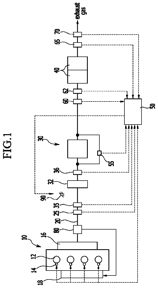
FIG. 1 is a diagrammatic view of a power system.
FIG. 2 is a graphical representation of soot loading in a diesel particulate filter during a first operation mode and a second operation mode.
FIG. 3 is a graphical representation of an engine speed-torque map and a boundary speed-torque curve under which a second operation mode is enabled.
FIG. 4 is a block diagram of strategies used in a second operation mode.
FIG. 5 is a graphical representation of soot loading in a diesel particulate filter illustrating a delay period and transition period.
FIG. 6 is a graphical representation of soot loading in a diesel particulate filter illustrating a delay period and transition period.
FIG. 7 is a graphical representation of soot loading in a diesel particulate filter exceeding a threshold and illustrating the engine's responses.
FIG. 8 is a graphical representation of hydrocarbon levels in a diesel particulate filter during a hydrocarbon removal calibration.
FIG. 9 is a graphical representation of a temperature profile and of soot loading profiles during a sulfur detection routine.
Detailed description
As seen in FIG. 1, a power system 1 includes an engine 10 and multiple other systems. These systems include a fuel system 20, an air intake system 30, an exhaust system 40, an aftertreatment system 50, an exhaust gas recirculation (EGR) system 60, and an electrical system 70. The power system 1 may include other features not shown, such as cooling systems, peripheries, drivetrain components, etc.
The engine 10 creates the power for the power system 1. The engine 10 includes a block 11, cylinders 12, and pistons 13. The pistons 13 reciprocate within the cylinder 12 to drive a crankshaft. The engine 10 may be any type of engine (internal combustion, gas, diesel, gaseous fuel, natural gas, propane, etc.), may be of any size, with any number of cylinders, and in any configuration ("V," in-line, radial, etc.). The engine 10 may be used to power any machine or other device, including on-highway trucks or vehicles, off-highway trucks or machines, earth moving equipment, generators, aerospace applications, locomotive applications, marine applications, pumps, stationary equipment, or other engine powered applications.
The fuel system 20 delivers a fuel 21 to the engine 10. The fuel system 20 includes a fuel tank 22, fuel line 23, fuel pump 24, fuel filter 25, fuel rail 26, and fuel injectors 27. The fuel tank 22 contains the fuel 21 and the fuel line 23 delivers the fuel 21 from the fuel tank 22 to the fuel rail 26. The fuel pump 24 draws the fuel 21 from the fuel tank 22 and passes the fad 21 to the fuel rail 26. In some embodiments, more than one fuel pump 24 may be used with a downstream fuel pump 24 having higher pressure capabilities than an upstream fuel pump 24. The fuel 21 may also pass through one or more fuel filters 25 to clean the fuel 21.
The fuel 21 is passed to the fuel injectors 27 via the fuel rail 26 and the fuel 21 is delivered into each cylinder 12 via the corresponding fuel injector 27. The fuel injectors 27 may include solenoid or piezoelectric valves to deliver the injection. The fuel rail 26 is pressurized by operation of the fuel pump 24. The fuel pump 24 may include a swash plate 28 that controls the compression ratio of the fuel pump 24. Changes in the swash plate 28 or other changes to the operation of the fuel pump 24 can be used to vary the pressure of the fuel 21 in the fuel rail 26 and therefore change the engine fuel injection pressure. The fuel system 20 is described above as a common rail fuel system, but other embodiments may be adapted for other fuel systems, such as unit injector systems.
The air intake system 30 delivers fresh intake air 31 to the engine 10. The air intake system 30 includes an airline 32, air cleaner 33, compressor 34, intake air cooler 35, intake valve 36, intake air heater 37, and intake manifold 38. The fresh intake air 31 is sucked in through the airline 32 and passes into the cylinder 12. The fresh air 31 is first drawn through the air cleaner 33, is then compressed by the compressor 34, and next cooled by the intake air cooler 35. The fresh air 31 may then pass through the intake valve 36 and intake air heater 37. The fresh air 31 is then delivered to the engine 10 via the intake manifold 38. Engine intake valves associated with each cylinder 12 may be used to deliver the air to the cylinders 12 for combustion.
The exhaust system 40 routes raw exhaust 41 from the engine 10 to the aftertreatment system 50. The exhaust system 40 includes an exhaust manifold 42, turbo 43, and backpressure valve 44. The backpressure valve 44 may include any controllable restriction placed on the exhaust, including a smart engine brake.
The turbo 43 includes the compressor 34, a turbine 45, a turbo shaft 46, and a wastegate 47. The turbine 45 is rotationally connected to the compressor 34 via the turbo shaft 46. The wastegate 47 includes a wastegate passage 48 and a wastegate valve 49. The wastegate passage 48 connects from upstream to downstream of the turbine 45 and the wastegate valve 49 is disposed inside the wastegate passage 48. In some embodiments a wastegate 47 may not be needed or included. In some embodiments the turbo 43 may include an asymmetric turbine 45 and separate exhaust manifolds 42 that may be used to drive EGR. In other embodiments the turbo 43 may include a variable geometry turbine 45 and separate exhaust manifolds 42 that may be used to drive EGR. Some embodiments may also include one or more additional turbos 43 in series or in parallel.
The backpressure valve 44 is downstream of the turbine 45 and upstream of the aftertreatment system 50. In other embodiments, the backpressure valve 44 may be located in the aftertreatment system 50, in the exhaust manifold 42, or elsewhere downstream of the engine 10.
The raw exhaust 41 is expunged from the engine 10 via the engine exhaust valves and is routed through the exhaust manifold 42 to the turbine 45. The hot raw exhaust 41 drives the turbine 45, which drives the compressor 34, and compresses the fresh intake air 31. The wastegate passage 48 allows the raw exhaust 41 to by-pass the turbine 45 when the wastgate valve 49 is opened. The wastegate passage 48 is controlled to regulate turbo 43 boost pressure and the wastegate valve 49 may be configured to open once a threshold boost pressure is reached.
The aftertreatment system 50 receives raw exhaust 41 and refines it to produce cleaned exhaust 51 that is routed to the atmosphere. The aftertreatment system 50 includes an exhaust conduit 52, a diesel oxidation catalyst (DOC) 53, and a diesel particulate filter (DPF) 54, which may be a catalyzed DPF 54. The DOC 53 and DPF 54 may be housed in a single canister 55, as shown, or individual canisters. An aftertreatment temperature represents the temperature of the DOC 53 and DPF 54 inside the canister 55. A muffler may also be included in the aftertreatment system 50.
The DOC 53 oxidizes Nitrogen monoxide (NO) into Nitrogen dioxide (NO2). The DOC 53 includes a catalyst or precious metal coating on a substrate. The substrate may have a honeycomb or other elongated channel structure or other high surface area configuration. The substrate may be made from cordierite or another suitable ceramic or metal. The precious metal coating may consist mainly of Platinum, though other catalytic coatings may be used. In one embodiment, the DOC 53 may have a precious metal loading of between 10 and 50 grams per cubic foot on a 200 to 600 cell per square inch DOC. While it may be used, a Palladium coating may not be needed because it is normally used for temperature stability above 500 degrees Celsius. The DOC may also include a washcoat coating to help hold the precious metal coating and provide additional reaction sites. The washcoat may be Alumina (AL2O3) based, or based on another suitable material.
Different types of DOCs are configured for different types of aftertreatment systems with different DPF 54 regeneration strategies. These different DPF 54 regeneration strategies may include low temperature, dosing, and upstream heat. The DOC 53 of the current aftertreatment system 50 may be characterized as a low temperature aftertreatment system DOC 53 because the DPF 54 is passively regenerated at relatively low temperatures. These low temperature DOCs require high precious metal loadings to achieve the level of NO2 production needed, but may not require Palladium for thermal stability.
Dosing DOCs require high precious metal loadings to create the quantity of exothermic reactions needed. These dosing DOCs may also require Palladium for thermal stability because of the temperatures that may be involved. The total precious metal loading of these dosing DOCs may be similar to the precious metal loading of the low temperature DOC described above.
Upstream heat DOCs are used for aftertreatment systems where a heat source, such as a heater or burner, is upstream of the DPF 54 to provide the heat for DPF 54 regeneration. These upstream heat DOCs do not require high precious metal loadings because the heat is coming from another source. However, these upstream heat DOCs may require Palladium for thermal stability because of the higher temperatures that may be involved. Aftertreatment temperatures greater than 500 degrees Celsius are often needed in these systems. These upstream heat DOCs may have a precious metal loading of between 5 and 25 grams per cubic foot on a 200 to 400 cell per square inch DOC. Because of the lower precious metal loadings, the upstream heat DOCs may be cheaper than the low temp or dosing DOCs.
The DPF 54 collects particulate matter (PM) or soot. The DPF 54 may also include a catalyst or precious metal and washcoat to help the DOC 53 with the oxidization of NO into Nitrogen dioxide (NO2). The catalyst of the DPF 54 is coated on a substrate with a honeycomb or other elongated channel or thin wall structure. The DPF 54 substrate may be more porous than the DOC 53 substrate and every other channel may be blocked with half the channels blocked at the inlet end and half blocked at the outlet end. This increased porosity and the blocked channels encourage wall flow of the exhaust. The wall how causes the soot to be filtered and collected in the DPF 54.
Like the DOC, different types of DPFs are configured for different types of aftertreatment systems with different DPF 54 regeneration strategies. For instance, the upstream heat aftertreatment systems may not need a DPF with any or only relatively little catalyst because less passive regeneration is needed.
Variations to the aftertreatment system 50 are possible. For instance, The DOC 53 may be enlarged, reducing or eliminating the need for any catalyst on the DPF 54. The DPF 54 may also be enlarged and the amount of catalyst coated increased to eliminate the need for the DOC 53. The types of catalysts may also be changed. Catalysts may also be added to fuel supply.
The aftertreatment system 50 may also include a Selective Catalytic Reduction (SCR) system to reduce NO and NO2 into N2. The SCR system may include a SCR catalyst and reductant system to add a supply of reductant in the SCR catalyst.
The EGR system 60 routs raw exhaust 41 to the air intake system 30, where the raw exhaust 41 mixes with the fresh air 31 to create a mixed air 61. The mixed air 61 is then delivered to the engine 10. Because the raw exhaust 41 has already been combusted by the engine 10 it contains less oxygen and is more inert than fresh air 31. Therefore the combustion of the mixed air 61 by the engine 10 generates less heat, which inhibits the formation of NOx.
The EGR system 60 includes an EGR take-off 62, an EGR line 63, an EGR cooler 64, an EGR valve 65, a reed valve 66, an EGR introduction port 67, and one or more EGR mixers 68. The EGR take-off 62 is fluidly coupled to the exhaust manifold 42 and EGR line 63. In other embodiments, the EGR take-off 62 may be isolated to a single or a single set of cylinders(s). In yet other embodiments, the EGR take-off 62 may be further downstream, possibly after or in the aftertreatment system 50. The EGR system 60 may also be adapted to be in-cylinder. The EGR cooler 64 is disposed in the EGR line 63 down stream of the EGR take-off 62. In some embodiments, the EGR cooler 64 and intake air cooler 35 may be combined. Some embodiments also may not include reed valves 66.
The EGR valve 65 is disposed in the EGR line 63 downstream of the EGR cooler 64. The reed valve 66 is disposed in the EGR line 63 downstream of the EGR valve 65. In other embodiments, the EGR valve 65 and/or reed valve 66 may be disposed upstream of the EGR cooler 64. The EGR introduction port 67 is fluidly connected to the EGR line 63 downstream of the reed valve 66. The EGR mixer 68 extends into the intake airline 32 to introduce and mix the raw exhaust 41 into the fresh air 31 to create the mixed air 61. In some embodiments the reed valve 66 and EGR mixer 68 may not be needed or included.
The electrical system 70 receives data from power system 1 sensors, processes the data, and controls the operation of multiple components in the power system 1. The electrical system 70 includes a controller 71, wiring harness 72, and a plurality of sensors. The controller 71 may embody an electronic control module (ECM) or another processor capable of receiving, processing, and communicating the needed data. The controller 71 may also embody multiple units working together. The controller 71 may be in communication with and/or control more or fewer components than is shown in the current embodiment. The controller 71 is configured or programmed to receive data and control the components of the power system 1 as described herein.
The sensors are all connected to the controller 71 via the wiring harness 72. In other embodiments wireless communication may be used instead of the wiring harness 72. The sensors may include a soot loading sensor 73, aftertreatment inlet temperature sensor 74, air intake temperature sensor 75, barometric pressure sensor 76, rail fuel temperature sensor 77, rail fuel pressure sensor 78, EGR gas temperature sensor 79, EGR valve inlet pressure sensor 80, EGR valve outlet pressure sensor 81, intake manifold temperature sensor 82, intake manifold pressure sensor 83, and an engine speed sensor 84. An EGR valve position sensor may also be included or the EGR valve position may be determined based on known command signals.
The soot loading sensor 73 provides an indication of the amount of soot loading in the DPF 54. The soot loading sensor 73 provides a reading corresponding to the mass or quantity of soot per volume of the DPF 54. The amount of soot loading may be expressed as a % of a maximum acceptable soot load for the DPF 54. The maximum acceptable soot load for the DPF 54 may be determined as the load at which the likelihood of a thermal event in the DPF 54 becomes higher than an arbitrary limit or threshold amount. Therefore, it is possible for the soot loading to be greater than 100% but it is not desirable.
The soot loading values may need to be corrected for different altitudes or barometric pressures which may be determined by the barometric pressure sensor 76. The soot loading values may also need to be corrected for an accumulation of ash in the DPF 54 over time. This correction may be made using a model or sensor that estimates the amount of ash. The more accurate and responsive the soot loading sensor 73, the more precisely the 100% soot loading value can be assigned.
In one embodiment, the soot loading sensor 73 may embody a radio frequency (RF) sensor. Such an RF sensor may pass radio frequencies through the DPF 54 and measure attenuated frequencies as an indication of particulate loading in the DPF 54. The soot loading sensor 73 may also measure other aspects inside or across the DPF 54 as an indication of soot loading. For instance, the soot loading sensor 73 may measure a pressure differential or temperature differential across the DPF 54. The soot loading sensor 73 may also embody a computer map, model, or algorithm that predicts particulate loading over time.
The aftertreatment inlet temperature sensor 74 measures the temperature of the raw exhaust 41 entering the aftertreatment system 50. The aftertreatment temperature may be determined via the aftertreatment inlet temperature sensor 74. The aftertreatment temperature may also be determined in other ways. For example, the aftertreatment temperature may be determined or extrapolated from engine maps, infrared temperature sensors, temperature sensors located upstream or downstream, or pressure sensors.
The air intake temperature sensor 75 measures the ambient temperature of the fresh air 31 entering the air intake system 30. The barometric pressure sensor 76 measures the barometric pressure of the power system 1 environment as an indication of altitude. The rail fuel temperature sensor 77 and rail fuel pressure sensor 78 measure the temperature and pressure inside the fuel rail 26 which is the engine fuel injection pressure. The EGR gas temperature sensor 79 measure the temperature of the raw exhaust 41 being mixed with the fresh air 31. The EGR valve inlet pressure sensor 80 and EGR valve outlet pressure sensor 81 measure the pressure on either side of the EGR valve 65. The intake manifold temperature sensor 82 and intake manifold pressure sensor 83 measures the temperature and pressure inside the intake manifold 38. The engine speed sensor 84 may measure the speed of the engine 10 by measuring speed of the camshaft, crankshaft, or other engine 10 component.
The wiring harness 72 is also connected to the backpressure valve 44, wastegate valve 49, fuel pump 24, engine 10, fuel injectors 27, EGR valve 65, intake valve 36, and intake air neater 37. The contract 71 controls the backpressure valve 44, wastegate valve 49, fuel pump 24, engine 10, fuel injectors 27, FOR valve 65, intake valve 36, and intake air heater 37.
The engine 10 generates soot that is collected by the DPF 54. The main constituent of soot is Carbon (C). The NO contained in the raw exhaust 41 is converted into NO2 as it passes over the DOC. The NO2 is next brought into contact with the Carbon trapped in the DPF 54. The NO2 from the DOC 53 and Carbon trapped in the DPF 54 then react to produce CO2 and NO, burning the soot. If the DPF is catalyzed the NO may be again converted to NO2 to enable further soot oxidation.
Above an aftertreatment light-off temperature the reactions described above may occur at a rate sufficient to burn at least as much soot as is being trapped, or to continuously regenerate the DPF 54. The aftertreatment light-off temperature may be approximately 230 degrees Celsius. In other embodiments, the aftertreatment light-off temperature may be between approximately 200 and 260 degrees Celsius. As the aftertreatment temperature rises above light-off temperature, the rate of reactions described above increase and the DPF 54 regenerates faster. Regeneration under these conditions may be referred to as low temperature regeneration.
FIGS. 2, 3, and 5-8 are graphical representations of power system operating conditions. It should be understood that the values presented are meant to be illustrative of aspects of the present disclosure and are not necessarily representative of expected or experienced data sets.
As seen in FIG. 2, under some engine 10 work or duty cycles or environments the aftertreatment temperature is high enough for a sufficient amount of time to continuously regenerate the DPF 54. However, FIG. 2 also shows that in some duty cycles or environments the aftertreatment temperature may be insufficient and the soot loading in the DPF may reach a regeneration activation soot threshold 103.
In order to account for situations where the regeneration activation soot threshold 103 is reached, the engine 10 includes a control system 100 that operates in either a first operation mode 101 or a second operation mode 102. The second operation mode 102, which may also be called a regeneration assist calibration, creates power system 1 conditions conducive to cause DPF 54 regeneration. Under most engine 10 work or duty cycles or environments and while the DPF 54 is under the regeneration activation soot threshold 103 the control system 100 operates the engine 10 in the first operation mode 101, which may also be called a standard calibration. The second operation mode 102 is described as being used with a low temperature aftertreatment system but may also be used in conjunction with the dosing or upstream heat aftertreatment systems to assist in regeneration.
FIG. 3 shows a graph of engine speed versus engine torque. The graph includes a peak rated speed-torque curve 104 and a threshold or boundary speed-torque curve 105. The boundary speed-torque curve 105 may be associated with engine 10 conditions that result in an aftertreatment temperature of above a light-off temperature of the DOC under normal operating conditions to enable continuous regeneration of the DPF 54. In one embodiment, the light-off temperature may be approximately 230 degrees Celsius. In other embodiments, the speed-torque curve 105 may associated with other aftertreatment temperature thresholds.
The shape of the boundary speed-torque curve 105 may change depending on the power system 1 and its installation. The engine 10 speed is determined by the engine speed sensor 84. The engine 10 torque is calculated as a function of engine 10 speed and a quantity of fuel 21 injected. The area under the boundary speed-torque curve 105 may be determined by a map populated with the engine speed and torque values.
If the engine 10 speed-torque is above the boundary speed-torque curve 105 then the second operation mode 102 is disabled and only the first operation mode 101 is employed. If the DPF 54 reaches the regeneration activation soot threshold 103 and the engine 10 speed and torque is below the boundary speed-torque curve 105 then the control system 100 operates the engine 10 in the second operation mode 102.
Once a regeneration deactivation soot threshold 106 is reached the control system 100 activates the first operation mode 101 again. Following this drop below the regeneration deactivation soot threshold 106, the second operation mode 102 will not be reactivated until the regeneration activation soot threshold 103 is again reached.
The establishment of the regeneration activation soot threshold 103 and regeneration deactivation soot threshold 106 is determined to avoid the use of the second operation mode 102 to the extent possible. In some embodiments the regeneration activation soot threshold 103 may be approximately 90%. In other embodiments, the regeneration activation soot threshold 103 may be between 70% and 100%, 85% and 95%, greater than 80%, or greater than 90%. In some embodiments the regeneration deactivation soot threshold 106 may be approximately 80%, in other embodiments, the regeneration deactivation soot threshold 106 may be between 65% and 85%, greater than 70%, or greater than 80%.
If the engine 10 speed and torque rises above the boundary speed-torque curve 105 while the engine 10 is in the second operation mode 102, then the second operation mode 102 may be interrupted and the first operation mode 101 will be activated. If following this interruption, the engine 10 speed and torque again drops below the boundary speed-torque curve 105 and the soot loading is above the regeneration deactivation soot threshold 106, then the second operation mode 102 will be reactivated. Once the engine 10 is shut off any history regarding whether the second operation mode 102 was active or whether an interruption had occurred may be lost or may be retained to continue operation of second operation mode 102 as though the no interruption occurred. The history may also be configured to be lost after a predetermined or threshold amount after the engine 10 is shutoff.
The second operation mode 102 is illustrated in FIG. 4. The second operation mode 102 employs a set of regeneration strategies 200 to create an engine outcome 205. The engine outcome 205 involves a higher exhaust temperature and a higher NOx/soot ratio. In this way the control system 100 achieves a target NOx/soot ratio 107 and target regeneration temperature 108 to accomplish regeneration of the DPF 54, as seen in FIG. 2. The target NOx/soot ratio 107 results in an accelerated low temperature continuous regeneration that may shorten the amount of time the second operation mode 102 is needed.
During the first operation mode 101, the NOx/soot ratio produced by the engine 10 may be greater than 20 grams of NOx per one gram of soot. During the second operation mode 102, the target NOx/soot ratio 107 produced by the engine 10 may risen to be greater than 35 grams of NOx per one gram of soot. In other embodiments, the target NOx/soot ratio 107 may be greater than 45 grams of NOx per one gram of soot during the second operation mode 102. In yet other embodiments, the target NOx/soot ratio 107 may be greater than 50 grams of NOx per one gram of soot during the second operation mode 102. The target NOx/soot ratio 107 may also be between 45 and 55 grams of NOx per one gram of soot during the second operation mode 102. In some embodiments, the target soot ratio 107 produced by the engine 10 may be approximately 50 grams of NOx per one gram of soot.
During the second operation mode 102 the target regeneration temperature 108 is above the light-off temperature and may be in a range between 200 and 400 degrees Celsius. In other embodiments the target regeneration temperature 108 is greater than 230 degrees Celsius during the second operation mode 102.
As described above, the DOC converts NO to NO2 and the NO2 reacts with the Carbon in the DPF 54 to form CO2 and NO. The second operation mode 102 increases the NOx/soot ratio in the raw exhaust 41 so that more NO2 is available to react with soot to form CO2 and NO at a faster rate. As mentioned above, the second operation mode 102 must also increase the temperature of the raw exhaust 41 to raise the aftertreatment temperature above the light-off temperature to enable these reactions. The second operation mode 102 also reduces the amount of soot in the raw exhaust 41 so that less Carbon is being trapped and the total soot loading in the DPF will be reduced faster.
In order to achieve the outcome 205, the second operation mode 102 employs multiple regeneration strategies 200 that change the operating parameters of the engine. These regeneration strategies 200 may include a backpressure valve strategy 210, EGR valve strategy 220, fuel injection timing strategy 230, fuel shot mode strategy 240, fuel pressure strategy 250, and an intake air heater strategy 260. While each individual strategy may impact NOx, temperature, and soot in different ways, they all work together to raise the aftertreatment temperature and raw exhaust 41 NOx/Soot ratio.
The type of regeneration strategies described herein are associated by some with reduced fuel efficiencies, increased engine 10 noise, reduced transient response, and added cost and complication. However, the power system 1 and control system 100 of the present disclosure minimizes these concerns.
The second operation mode 102 will, under most operating conditions, rarely be needed or used. The second operation mode 102 and use of the regeneration strategies 200 also actually reduces the additional hardware (heaters, burners, (losers, etc.) required by other DPF regeneration systems. The use of multiple regeneration strategies 200 together may also help maximize the NOx/soot ratio and temperature to assist regeneration or achieve accelerated regeneration of the DPF 54 and reduce the length of time the second operation mode 102 is utilized or needed. While the second operation mode 102 may result in an increase in the amount of soot, it also increases the amount NOx more so that a higher NOx/soot ratio results. Alternatively, the second operation mode 102 may reduce NOx and reduce soot more so that a higher NOx/soot ratio again results.
The high NOx/soot ratio also reduces the temperatures and time at temperature needed for regeneration of the DPF 54, which reduces the thermal stress on the DPF 54 and any aging or deactivation of the DPF 54. The aging of the DPF 54 may include the sintering of the catalyst, which may block channels and reduce performance as a function of time and temperature.
The time needed for the second operation mode 102 to lower the soot loading of the DPF 54 below the regeneration deactivation soot threshold 106 may range between approximately 20 minutes and 60 minutes. The time required varies depending largely on various conditions that also impact the aftertreatment temperature and may be longer or shorter than the times mentioned. The conditions affecting the time needed for the second operation mode 102 to lower the soot loading of the DPF 54 below the regeneration deactivation soot threshold 106 may include ambient air temperature, parasitic load levels, low engine idle speed, exhaust conduit 52 length, design and sizing of the air intake system 30, turbo 43 arrangements, insulation, engine compartment size, and many other factors.
The backpressure valve strategy 210 involves closing the backpressure valve 44. Closing the backpressure valve 44 increases the pressure in the exhaust system 40, causing the governor to increase the amount of fuel 21 injected in the engine 10 to maintain the engine 10 speed. The increase in the fuel 21 injected may result in a decrease in fuel efficiency, but it also results in an increase in the temperature of the raw exhaust 41 and aftertreatment temperature.
The amount the backpressure valve 44 is closed depends upon the engine 10 speed. The backpressure valve 44 is closed by an amount to achieve the needed aftertreatment temperature whilst avoiding an engine 10 stall. At low speeds the backpressure valve may be 98% closed at maximum, while at higher speed the backpressure valve 44 may be only 60% closed at maximum. The percentage the backpressure valve 44 is closed is the percentage of cross sectional area in the exhaust conduit obstructed compared to when the backpressure valve 44 is fully opened. The percentage that the backpressure valve is closed may vary based on the specific valve design being used.
At low speeds the closing of the backpressure valve 44 may cause a pressure differential between the intake manifold 38 and exhaust manifold 42 of between 150 and 300 kPa, compared to a pressure differential of between 3 and 7 kPa when not closed. At high speeds the closing of the backpressure valve 44 may cause a pressure differential between the intake manifold 38 and exhaust manifold 42 of between 50 and 100 kPa, compared to a pressure differential of between 40 and 50 kPa when not closed. The pressure differential ranges listed above may vary based on turbo 43 size and match and other power system 1 changes.
The closing of the backpressure valve 44 may be done at a slow rate to build pressure at a slow controlled rate in the exhaust manifold 42. The amount the backpressure valve 44 is closed and the corresponding pressure differentials discussed above may depend greatly on a number of factors, including the turbo 43 type/sizing/match, intake manifold 38 size, exhaust manifold 42 size, EGR line 63 size, backpressure from the aftertreatment system 50, and many other factors.
The operation of the backpressure valve 44 is controlled by the measured or determined pressure differential between the intake manifold 38 and exhaust manifold 42. The pressure in the intake manifold 38 is determined by the intake manifold pressure sensor 83. The pressure in the exhaust manifold 42 is determined by the EGR valve inlet pressure sensor 80. As described below, the EGR valve 65 is closed during the second operation mode 102 and therefore the pressure at the EGR valve inlet pressure sensor 80 will be the same as the pressure in the exhaust manifold 42. In an alternative embodiment, the pressure in the exhaust manifold 42 may be determined by a pressure sensor added in the exhaust manifold 42. The addition of a pressure sensor in the exhaust manifold 42 may be required if in an alternative embodiment the EGR valve is not completely closed or the EGR system 60 is not included or changed.
The operation of the backpressure valve 44 may also be controlled by the aftertreatment temperature. However, the pressure differential between the intake manifold 38 and exhaust manifold 42 may be more responsive. Using the aftertreatment temperature to control the operation of the backpressure valve 44 may require waiting for the temperature to rise as a result of the pressure differential.
Control based on aftertreatment temperature may be used if control based on pressure differential between the intake manifold 38 and exhaust manifold 42 does not result in a aftertreatment temperature that exceeds the light-off temperature of the DOC 53. The failure to reach the desired aftertreatment temperature despite achieving a targeted pressure differential between the intake manifold 38 and exhaust manifold 42 may be a result of cold ambient conditions or installations with aftertreatment systems 50 that are far downstream. In these situations, the backpressure valve 44 may be controlled based on the aftertreatment temperature and closed to a greater percentage than would be dictated by the pressure differential between the intake manifold 38 and exhaust manifold 42. In one embodiment, however, the pressure differential between the intake manifold 38 and exhaust manifold 42 will not be allowed to exceed a maximum value (for example 300 kPa).
Control based on the aftertreatment temperature may also be used if control based on pressure differential between the intake manifold 38 and exhaust manifold 42 results in the aftertreatment temperature exceeding a predetermined or threshold aftertreatment maximum temperature (for example 400 degrees Celsius). Exceeding the aftertreatment maximum temperature may result in damage to the DOC 53 and/or DPF 54, as described above. In these situations, the backpressure valve 44 may be controlled based on the aftertreatment temperature and opened a greater percentage than would be dictated by the pressure differential between the intake manifold 38 and exhaust manifold 42. Exceeding the aftertreatment maximum temperature may also result in a warning to the operator.
The operation of the backpressure valve 44 may also be controlled by the absolute pressure in the exhaust manifold 42. However, using the pressure differential between the intake manifold 38 end exhaust manifold 42 may reduce the need to account for the impact altitude has on absolute pressure.
If the backpressure valve 44 fails to close or respond to commands, the second operation mode 102 may be modified to use more or less of the other regeneration strategies 200 and/or de-rate the engine 10.
In order to keep the backpressure valve 44 functioning properly and to test its operation in What may be a harsh environment, movements of the backpressure valve 44 may be carried out. These movements may be done periodically (for example every 30 minutes). The degree of the movement may depend on an exhaust mass flow rate, with larger movements being done at lower exhaust mass flow rates and smaller movements at higher exhaust mass flow rate. The exhaust mass flow rate may be determined as a function of engine 10 speed, a sensor, output, or another power system 1 condition. The larger movements provide more benefit to backpressure valve 44 operation and testing, while smaller movements may be required at higher speeds to reduce the impact on engine 10 performance during the test. The movements of the backpressure valve 44 may also be restricted to only occur at low engine 10 speeds where performance impact is less of a concern.
An additional strategy or an alternative to the backpressure valve strategy 210 may be an intake valve strategy. Either or both the intake valve 36 or backpressure valve 44 may be referred to as regeneration valves that are used to assist in the regeneration of the DPF 54. In one embodiment, closing of the intake valve 36 reduces the amount of fresh intake air 31 being supplied to the engine 10 and increases pumping losses, which increases temperatures. The backpressure valve strategy 210 may be more effective than the intake valve strategy because the backpressure valve strategy 210 does not reduce manifold pressure and is therefore less susceptible to misfire. In some embodiments, the intake valve 36 may not be needed or included in the power system 1.
The EGR valve strategy 220 involves closing the EGR valve 65 during the second operation mode 102 or while the backpressure valve 44 is at least partially closed. However, the EGR valve 65 may not always need be closed while the backpressure valve 44 is at least partially closed, especially if the backpressure valve 44 is being used for thermal management of other aftertreatment devices, such as an SCR system or the DOC 53. Closing the EGR system 60 increases the amount of NOx produced. Closing the EGR system 60 also prevents high levels of flow through the EGR system 60 while the backpressure valve 44 is partially closed. This flow could cause an imbalance of raw exhaust 41 to fresh air 31 in the mixed air 61 and may reduce the effectiveness of the backpressure valve strategy 210.
In some embodiments, the backpressure valve 44 will be kept completely open or open to a greater extent than it otherwise would be if a failure of the EGR valve 65 to close occurs. The EGR valve strategy 220 may be eliminated in power systems without an EGR system or modified in power systems that have in-cylinder EGR systems.
The description continues in the full USPTO document.
 Lapsed, fee not paid3 drawings