Lapsed, fee not paid5 drawings
Hardware & Electronics · US 8,775,897 B2
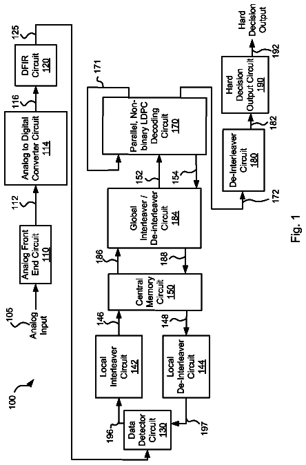
Data processing system with failure recovery
Various embodiments of the present invention provide systems and methods for a data processing system with failure recovery.
US 8,775,913 B2 · Assignee: LSI Corporation · Inventors: Haratsch; Erich F. et al.
Sheet 1 of 19 from the published document. All sheets in the USPTO PDF
Methods and apparatus are provided for computing soft data or log likelihood ratios for received values in communication or storage systems. Soft data values or log likelihood ratios are computed for received values in a communication system or a memory device by obtaining at least one received value; identifying a segment of a function corresponding to the received value, wherein the function is defined over a plurality of segments, wherein each of the segments has an associated set of parameters; and calculating the soft data value or log likelihood ratio using the set of parameters associated with the identified segment. The computed soft data values or log likelihood ratios are optionally provided to a decoder.
A number of storage and communication systems use analog values to represent information. For example, storage devices use analog memory cells to store an analog value, such as an electrical charge or voltage, to represent the information stored in the cell. In flash memory devices, for example, each analog memory cell typically stores a certain voltage. The range of possible analog values for each cell is typically divided into threshold regions, with each region corresponding to one or more data bit values. Data is written to an analog memory cell by writing a nominal analog value that corresponds to the desired one or more bits. In multi-level NAND flash memory devices, for example, floating gate devices are employed with programmable threshold voltages in a range that is divided into multiple intervals with each interval corresponding to a different multibit value. To program a given
1 of 19 drawing sheets so far from the published document, cropped to the drawing. Every sheet is in the USPTO PDF.
What the patent claimed, word for word. All of it is now free to use.
The present application is related to U.S. patent application entitled "Methods and Apparatus for Computing a Probability Value of a Received Value in Communication or Storage Systems," and U.S. patent application entitled "Methods and Apparatus for Approximating a Probability Density Function or Distribution for a Received Value in Communication or Storage Systems," each filed contemporaneously herewith, and International Patent Application Serial No. PCT/US09/49326, entitled "Methods and Apparatus for Read-Side Intercell Interference Mitigation in Flash Memories," filed Jun. 30, 2009; International Patent Application Serial No. PCT/US09/49333, entitled "Methods and Apparatus for Soft Demapping and Intercell Interference Mitigation in Flash Memories," filed Jun. 30, 2009; and International Patent Application Serial No. PCT/US09/59077, entitled "Methods and Apparatus for Soft Data Generation for Memory Devices," filed Sep. 30, 2009, each incorporated by reference herein.
The present invention relates generally to techniques for detection and decoding in storage and communication systems, and more particularly, to methods and apparatus for computing soft data values or log likelihood ratios for received values in communication systems or memory devices.
A number of storage and communication systems use analog values to represent information. For example, storage devices use analog memory cells to store an analog value, such as an electrical charge or voltage, to represent the information stored in the cell. In flash memory devices, for example, each analog memory cell typically stores a certain voltage. The range of possible analog values for each cell is typically divided into threshold regions, with each region corresponding to one or more data bit values. Data is written to an analog memory cell by writing a nominal analog value that corresponds to the desired one or more bits.
In multi-level NAND flash memory devices, for example, floating gate devices are employed with programmable threshold voltages in a range that is divided into multiple intervals with each interval corresponding to a different multibit value. To program a given multibit value into a memory cell, the threshold voltage of the floating gate device in the memory cell is programmed into the threshold voltage interval that corresponds to the value.
The analog values stored in memory cells are often distorted. The distortions are typically due to, for example, back pattern dependency (BPD), noise and intercell interference (ICI). For a more detailed discussion of distortion in flash memory devices, see, for example, J. D. Lee et al., "Effects of Floating-Gate Interference on NAND Flash Memory Cell Operation," IEEE Electron Device Letters, 264-266 (May 2002) or Ki-Tae Park, et al., "A Zeroing Cell-to-Cell Interference Page Architecture With Temporary LSB Storing and Parallel MSB Program Scheme for MLC NAND Flash Memories," IEEE J. of Solid State Circuits, Vol. 43, No. 4, 919-928, (April 2008), each incorporated by reference herein.
A probability density function (PDF) of a continuous random variable describes the relative probability that a given value of the random variable will occur at a given point in time. The voltage distributions for memory cells, for example, are often expressed using such probability density functions. Generally, the threshold voltage of a cell is the voltage that needs to be applied to the cell so that the cell conducts a certain amount of current. The threshold voltage is a measure for the data stored in a cell.
Statistical noise in a communication system, for example, is typically approximated using a probability density function having a normal distribution (often referred to as a Gaussian distribution). Computing probability values for a Gaussian distribution is relatively straightforward. The above-described distortions in memory devices, however, as well as imperfections in the write process, may cause the probability density function for received values read from the memory to have an arbitrary or non-Gaussian distribution. The computation of probability values for such arbitrary distributions is significantly more complex than for a Gaussian distribution.
A need therefore exists for improved methods and apparatus for computing probability values for received or stored values that have an arbitrary probability density function. Yet another need exists for improved methods and apparatus for computing probability values for an arbitrary PDF that are based on techniques for computing probability values for a predefined PDF, such as a Gaussian PDF. Among other benefits, such improved techniques for computing probability values for received or stored values will lower the computational complexity of devices incorporating such techniques. A further need exists for methods and apparatus for computing soft data values or log likelihood ratios for received values in communication systems or memory devices.
Generally, methods and apparatus are provided for computing soft data or log likelihood ratios for received values in communication or storage systems. According to one aspect of the invention, soft data values or log likelihood ratios are computed for received values in a communication system or a memory device by obtaining at least one received value; identifying a segment of a function corresponding to the received value, wherein the function is defined over a plurality of segments, wherein each of the segments has an associated set of parameters; and calculating the soft data value or log likelihood ratio using the set of parameters associated with the identified segment. The function can be derived, for example, using a distribution or a probability density function. The computed soft data values or log likelihood ratios are optionally provided to a decoder.
The identifying step can identify a plurality of segments each having an associated set of parameters. The calculating step can then calculate the soft data value or the log likelihood ratio using the sets of parameters. The parameters can be stored in a table or obtained by evaluating an expression. For example, a table can have an entry to store the parameters for
one or more performance factors;
one or more states; and
one or more data patterns.
A more complete understanding of the present invention, as well as further features and advantages of the present invention, will be obtained by reference to the following detailed description and drawings.
FIG. 1 is a schematic block diagram of a conventional flash memory system;
FIG. 2 illustrates an exemplary threshold voltage distribution for the exemplary flash memory of FIG. 1;
FIG. 3 illustrates the architecture of an exemplary flash cell array in a multi-level cell (MLC) flash memory device;
FIGS. 4 and 5 illustrate exemplary threshold voltage distributions over time for an exemplary multi-level cell flash memory in the presence of significant distortions;
FIG. 6 illustrates an exemplary flash cell array in a multi-level cell (MLC) flash memory device in further detail;
FIG. 7 illustrates the disturbances that are present for a target cell due to a number of exemplary aggressor cells, such as intercell interference, back pattern dependency, noise and other distortions;
FIG. 8 is a schematic block diagram of an exemplary flash memory system incorporating controller-based probability computation and soft demapping/soft data generation techniques in accordance with the present invention;
FIG. 9A illustrates an exemplary flash memory system with controller-based soft data generation using probability computations in accordance with one embodiment of the present invention;
FIG. 9B illustrates a segment-dependent LLR computation block in accordance with an alternate implementation of the exemplary flash memory system of FIG. 9A;
FIG. 10A is a flow chart describing an exemplary soft demapping process to generate soft information or log-likelihood ratios (LLRs) using segment-dependent probability computations;
FIG. 10B is a flow chart describing an exemplary segment-dependent LLR computation process according to an alternate segment-dependent LLR embodiment of the present invention.
FIG. 11 illustrates an exemplary probability density function for a received or stored value of interest, for example a threshold voltage of a flash memory cell in an exemplary embodiment;
FIG. 12 is a flow chart describing an exemplary implementation of a probability computation process incorporating features of the present invention;
FIG. 13 is a flow chart describing an exemplary PDF approximation process for determining the parameters of a piecewise linear function;
FIG. 14 is a block diagram of an exemplary system that employs the parameters of a piece-wise linear function to compute probability values;
FIGS. 15 through 17 illustrate the approximation of a probability density function for an arbitrary random variable, r, using a Gaussian approximation in accordance with the present invention;
FIG. 18 is a sample table for an exemplary probability parameter look-up table that records the parameters for each segment of the piecewise linear mapping function; and
FIG. 19 illustrates an exemplary collection of probability density functions for a given target cell of an exemplary multi-level cell flash memory, based on all the possible values of each aggressor cell.
The present invention provides methods and apparatus for computing probability values for an arbitrary PDF. As previously indicated, the computation of probability values for a Gaussian distribution is relatively straightforward. Generally, for a Gaussian PDF, the log likelihood calculation simplifies to a distance calculation as a Gaussian PDF is completely defined by its mean and variance. The present invention recognizes that when a random variable has an arbitrary distribution, however, the computation of the probability values is significantly more complex.
According to one aspect of the present invention, methods and apparatus are provided for computing probability values for an arbitrary PDF that are based on techniques for computing probability values for a predefined PDF, such as a Gaussian PDF. In one exemplary implementation, the present invention employs a mapping function, .phi., to map a Gaussian PDF, f.sub.x(x), to an arbitrary probability function of interest, f.sub.r(r). In further variations, non-Gaussian PDFs that can be described with predefined analytical functions can be mapped to arbitrary PDFs.
The present invention recognizes that it may be difficult in some applications to find the mapping function, .phi.. Thus, according to another aspect of the invention, the mapping function, .phi., is approximated with a piecewise linear function, .phi., comprised of a plurality of linear segments. Thus, within each segment, a Gaussian approximation is used to compute the probabilities for the variable r with the random PDF. In a further variation, the mapping function, .phi., is defined over a plurality of segments, where each segment has a set of parameters. Thus, within each segment, the probabilities for the variable r with the random PDF are computed based on a predefined PDF, such as a Gaussian PDF, and the corresponding set of parameters.
The present invention can be used, for example, to compute probability values in memory devices, such as single-level cell or multi-level cell (MLC) NAND flash memory devices. As used herein, a multi-level cell flash memory comprises a memory where each memory cell stores two or more bits. Typically, the multiple bits stored in one flash cell belong to different pages. While the invention is illustrated herein using memory cells that store an analog value as a voltage, the present invention can be employed with any storage mechanism for memory devices, such as the use of voltages, resistances or currents to represent stored data, as would be apparent to a person of ordinary skill in the art. In addition, while the present invention is illustrated herein in the context of exemplary storage systems, the present invention can also be applied to a communication system, as would be apparent to a person of ordinary skill in the art.
FIG. 1 is a schematic block diagram of a conventional flash memory system 100. As shown in FIG. 1, the exemplary flash memory system 100 comprises a flash control system 110 and a flash memory block 160. The exemplary flash control system 110 comprises a flash controller 120, an encoder/decoder block 140 and one or more buffers 145. In an alternative embodiment, the encoder/decoder block 140 and some buffers 145 may be implemented inside the flash controller 120. The encoder/decoder block 140 and buffers 145 may be implemented, for example, using well-known commercially available techniques and/or products.
The exemplary flash memory block 160 comprises a memory array 170 and one or more buffers 180 that may each be implemented using well-known commercially available techniques and/or products. The memory array 170 may be embodied as a single-level or multi-level cell flash memory, such as a NAND flash memory, a phase-change memory (PCM), an MRAM memory, a NOR flash memory or another non-volatile flash memory. While the invention is illustrated primarily in the context of a multi-level cell NAND flash memory, the present invention can be applied to single-level cell flash memories and other non-volatile memories as well, as would be apparent to a person of ordinary skill in the art.
Multi-Level Cell Flash Memory
In a multi-level cell NAND flash memory, a threshold detector is typically employed to translate the voltage value associated with a particular cell to a predefined memory state. FIG. 2 illustrates an exemplary threshold voltage distribution for the exemplary multi-level cell flash memory 170 of FIG. 1, based on the teachings of U.S. Pat. No. 6,522,580, incorporated by reference herein. Generally, the threshold voltage of a cell is the voltage that needs to be applied to the cell so that the cell conducts a certain amount of current. The threshold voltage is a measure for the data stored in a cell.
In the exemplary embodiment shown in FIG. 2, each storage element employs four possible data states to store two bits of data in each memory cell. FIG. 2 illustrates four peaks 210-213, with each peak corresponding to one state. In a multi-level cell flash device, the different peaks 210-213 of the threshold voltage distribution graph 200 are used for storing two bits in the cell.
The peaks 210-213 of the threshold voltage distribution graph 200 are labeled with corresponding binary values. Thus, when a cell is in a first state 210, it represents a "1" for the lower bit (also known as least significant bit, LSB) and a "1" for the upper bit (also known as most significant bit, MSB). State 210 is generally the initial unprogrammed or erased state of the cell. Likewise, when a cell is in the second state 211, it represents a "0" for the lower bit and a "1" for the upper bit. When a cell is in the third state 212, it represents a "0" for the lower bit and a "0" for the upper bit. Finally, when a cell is in the fourth state 213, it represents a "1" for the lower bit and a "0" for the upper bit.
Threshold voltage distribution 210 represents a distribution of the threshold voltages V.sub.t of the cells within the array that are in an erased state ("11" data state), with negative threshold voltage levels below 0 volts. Threshold voltage distributions 211 and 212 of memory cells storing "10" and "00" user data, respectively, are shown to be between 0 and 1 volts and between 1 and 2 volts, respectively. Threshold voltage distribution 213 shows the distribution of cells that have been programmed to the "01" data state, with a threshold voltage level set between 2 and 4.5 volts of the read pass voltage.
Thus, in the exemplary embodiment of FIG. 2, 0 volts, 1 volt and 2 volts can be used as voltage level thresholds between each level or state. The voltage level thresholds are used by the flash memory 160 (e.g., sensing circuits in the flash memory 160) to determine the voltage level or state of a given cell. The flash memory 160 will assign one or more bits to each cell based on a comparison of the measured voltages to the voltage level thresholds, which are then transmitted as hard decisions to the flash control system 110. In addition or alternatively, in an implementation using soft information, the flash memory 160 may transmit the measured voltages or a quantized version of the measured voltages to the flash control system 110 as soft information, where a larger number of bits is used to represent the measured voltage than the number of bits stored in the memory cell.
It is further noted that cells are typically programmed using well-known Program/Verify techniques. Generally, during a Program/Verify cycle, the flash memory 160 gradually applies an increasing voltage to store a charge in the cell transistor until a minimum target threshold voltage is exceeded. For example, when programming a `10` data state in the example of FIG. 2, the flash memory 160 may gradually apply an increasing voltage to store a charge in the cell transistor until a minimum target threshold voltage of 0.4V is exceeded.
As discussed further below, each of the two bits stored in a single memory cell is from a different page. In other words, each bit of the two bits stored in each memory cell carries a different page address. The right side bit shown in FIG. 2 is accessed when a lower page address is input. The left side bit is accessed when an upper page address is input.
FIG. 3 illustrates the architecture of an exemplary flash cell array 300 in a multi-level cell (MLC) flash memory device 160, where each exemplary cell typically corresponds to a floating-gate transistor that stores two bits. In FIG. 3 each cell is associated with two numbers for the two pages to which the two bits belong. The exemplary cell array section 300 shows wordlines n through n+2 and four bitlines. The exemplary flash cell array 300 is partitioned into even and odd pages, where for example cells with even numbers (such as the cell with the numbers 0 and 2) correspond to even pages, and cells with odd numbers (such as the cell with the numbers 1 and 3) correspond to odd pages. Wordline n stores for example even pages 0 and 2 in the even bitlines, and odd pages 1 and 3 in the odd bit lines.
In addition, FIG. 3 indicates an exemplary program sequence where either an even or odd bitline cell is selected and programmed sequentially (bottom up) in the indicated order. The numbers indicate the order in which the pages are programmed. For example, page 0 is programmed before page 1. For a further discussion of the programming of even and odd pages, see for example K.-T. Park et al., "A Zeroing Cell-to-Cell Interference Page Architecture with Temporary LSB Storing and Parallel MSB Program Scheme for MLC NAND Flash Memories," IEEE Journal of Solid-State Circuits, Vol. 43, No. 4, 919-928 (April 2008), incorporated by reference herein.
As previously indicated, the analog values stored in memory cells and transmitted in communication systems are often distorted, for example, due to back pattern dependency, noise and intercell interference. Thus, the present invention recognizes that the threshold voltage distributions shown in FIG. 2 will not have Gaussian distributions in the presence of such distortions.
FIG. 4 illustrates an exemplary threshold voltage distribution for an exemplary multi-level cell flash memory in the presence of significant distortions. As previously indicated, the threshold voltage of a cell is the voltage that needs to be applied to the cell so that the cell conducts a certain amount of current. The threshold voltage is a measure for the data stored in a cell.
In the exemplary embodiment shown in FIG. 4, each storage element employs four possible data states to store two bits of data in each memory cell. FIG. 4 illustrates four peaks 410-413, with each peak corresponding to one state. In a multi-level cell flash device, the different peaks 410-413 of the threshold voltage distribution graph 400 are used for storing two bits in the cell. The peaks 410-413 of the threshold voltage distribution graph 400 are labeled with corresponding binary values, in a similar manner to FIG. 2.
Threshold voltage distribution 410 represents a distribution of the threshold voltages V.sub.t of the cells within the array that are in an erased state ("11" data state), with negative threshold voltage levels below 0 volts. Threshold voltage distributions 411 and 412 of memory cells storing "10" and "00" user data, respectively, are shown to be between 0 and 1 volts and between 1 and 2 volts, respectively. Threshold voltage distribution 413 shows the distribution of cells that have been programmed to the "01" data state, with a threshold voltage level set between 2 and 4.5 volts of the read pass voltage. Thus, in the exemplary embodiment of FIG. 4, 0 volts, 1 volt and 2 volts can be used as voltage level thresholds between each level or state.
For the exemplary threshold voltage distributions shown in FIG. 4, peak 410 tends to have the widest distribution, relative to the other peaks 411-413. In addition, the present invention recognizes that the exemplary threshold voltage distributions will change over time, for example, due to cycling and aging. Thus, FIG. 5 illustrates the exemplary threshold voltage distributions of FIG. 4 after the passage of some time and cycling. Generally, the peaks 510-513 in FIG. 5, tend to have a wider distribution and be more arbitrary, relative to the corresponding peaks 410-413 of FIG. 4, and the peaks 510-513 may even overlap as a result.
FIG. 6 illustrates an exemplary flash cell array 600 in a multi-level cell (MLC) flash memory device 160 in further detail. As shown in FIG. 6, the flash cell array 600 stores three bits per flash cell, c.sub.i. FIG. 6 illustrates the flash cell array architecture for one block, where each exemplary cell typically corresponds to a floating-gate transistor that stores three bits. The exemplary cell array 600 consists of m wordlines and n bitlines. Typically, in current multi-page cell flash memories the bits within a single cell belong to different pages. In the example of FIG. 6, the three bits for each cell correspond to three different pages, and each wordline stores three pages. In the following discussion, pages 0, 1, and 2 are referred to as the lower, middle, and upper page levels within a wordline.
As indicated above, a flash cell array can be further partitioned into even and odd pages, where for example cells with even numbers (such as cells 2 and 4 in FIG. 6) correspond to even pages, and cells with odd numbers (such as cells 1 and 3 in FIG. 6) correspond to odd pages. In this case, a page (such as page 0) would contain an even page even page 0) in even cells and an odd page (odd page 0) in odd cells.
Intercell Interference and other Disturbances
FIG. 7 illustrates the disturbances that are present for a target cell 710 due to a number of exemplary aggressor cells 720, such as intercell interference, back pattern dependency, noise and other distortions. The following notations are employed in FIG. 7:
WL: wordline;
BL: bitline;
BLo: odd bitline;
BLe: even bitline; and
C: capacitance.
ICI, for example, is caused by aggressor cells 720 that are programmed after the target cell 710 has been programmed. The ICI changes the voltage, V.sub.t, of the target cell 710. In the exemplary embodiment, a "bottom up" programming scheme is assumed and adjacent aggressor cells in wordlines i and i+1 cause ICI for the target cell 710. With such bottom-up programming of a block, ICI from the lower wordline i-1 is removed, and up to five neighboring cells contribute to ICI as aggressor cells 720, as shown in FIG. 7. It is noted, however, that the techniques disclosed herein can be generalized to cases where aggressor cells from other wordlines, such as wordline i-1, contribute to ICI as well, as would be apparent to a person of ordinary skill in the art. If aggressor cells from wordlines i-1, i and i+1 contribute to ICI, up to eight closest neighboring cells need to be considered. Other cells that are further away from the target cell can be neglected, if their contribution to ICI is negligible. In general, the aggressor cells 720 are identified by analyzing the programming sequence scheme (such as bottom up or even/odd techniques) to identify the aggressor cells 720 that are programmed after a given target cell 710.
Generally, V.sub.t is the voltage representing the data stored on a cell and obtained during a read operation. V.sub.t can be obtained by a read operation, for example, as a soft voltage value with more precision than the number of bits stored per cell, or as a value quantized to a hard voltage level with the same resolution as the number of bits stored per cell (e.g., 3 bits for 3 bits/cell flash).
For a more detailed discussion of ICI mitigation techniques, see, for example, International Patent Application Serial No. PCT/US09/49326, entitled "Methods and Apparatus for Read-Side Intercell Interference Mitigation in Flash Memories;" or International Patent Application Serial No. PCT/US09/49327, entitled "Methods and Apparatus for Write-Side Intercell Interference Mitigation in Flash Memories," each incorporated by reference herein.
Probability Computation
While the present invention is illustrated in the context of probability computations for a soft demapper in a flash control system, the present invention can be employed in any system where probabilities are computed for a received value in a storage or communications system, as would be apparent to a person of ordinary skill in the art. For example, the present invention can be employed in MAP detectors and iterative decoders and/or demappers that use probabilities, such as those based on LDPC coding, turbo coding, the Soft-Output Viterbi Algorithm (SOVA) or BCJR algorithm. For a more detailed discussion of exemplary LDPC decoders, see, for example, U.S. Pat. No. 7,647,548, incorporated by reference herein. For a more detailed discussion of exemplary SOVA detectors, see, for example, J. Hagenauer and P. Hoeher, "A Viterbi Algorithm with Soft-decision Outputs and its Applications," IEEE Global Telecommunications Conference (GLOBECOM), vol. 3, 1680-1686 (November 1989). For a more detailed discussion of exemplary BCJR detectors, see, for example, L. Bahl, J. Cocke, F. Jelinek, and J. Raviv, "Optimal Decoding of Linear Codes for Minimizing Symbol Error Rate," IEEE Trans. on Information Theory, Vol. IT-20(2), 284-87 (March 1974). For a more detailed discussion of Turbo coding, see, for example, J. Hagenauer, E. Offer and L. Papke, "Iterative decoding of binary block and convolutional codes," IEEE Transactions on Information Theory, 429-445 (March 1996).
The present invention provides probability computation techniques for communication and storage systems, such as flash memories. In one example, probability values are computed based on data read by the flash memory, where the read data values have a distribution that is arbitrary or non-Gaussian. The generated probability information can optionally be used for soft decision decoding. As used herein, the term "probability density functions" shall include probability density functions, distributions and approximations thereof, such as histograms and Gaussian approximations.
FIG. 8 is a schematic block diagram of an exemplary flash memory system 800 incorporating controller-based probability computation techniques in accordance with the present invention. As shown in FIG. 8, the exemplary flash memory system 800 comprises a flash control system 810 and a flash memory block 860, connected by an interface 850. The exemplary flash control system 810 comprises a flash controller 820 and a read channel 825, typically on one or more integrated circuits.
The exemplary read channel 825 comprises a signal processing unit 830, an encoder/decoder block 840 and one or more buffers 845. It is noted that the term "read channel" can encompass the write channel as well. In an alternative embodiment, the encoder/decoder block 840 and some buffers 845 may be implemented inside the flash controller 820. The encoder/decoder block 840 and buffers 845 may be implemented, for example, using well-known commercially available techniques and/or products, as modified herein to provide the features and functions of the present invention.
The exemplary signal processing unit 830 comprises one or more processors that implement one or more probability computation processes 835, discussed further below in conjunction with, for example, FIG. 12. The exemplary flash memory block 860 comprises a memory array 870 and one or more buffers 880 that may each be implemented using well-known commercially available techniques and/or products.
It is noted that the probability computation process 835 may optionally be implemented in the flash memory block 860, as would be apparent to a person of ordinary skill in the art. For a more detailed discussion of this alternate implementation of the signal processing unit in the flash memory, see, International Patent Application Serial No. PCT/US09/59077, entitled "Methods and Apparatus for Soft Data Generation for Memory Devices," filed Sep. 30, 2009 and incorporated by reference herein.
The exemplary signal processing unit 830 may also include one or more soft demapper and/or soft data generation processes that utilize the computed probability values. The interface 850 may optionally be implemented, for example, in accordance with the teachings of International PCT Patent Application Serial No. PCT/US09/49328, entitled "Methods and Apparatus for Interfacing Between a Flash Memory Controller and a Flash Memory Array", filed Jun. 30, 2009 and incorporated by reference herein, which increases the information-carrying capacity of the interface 850 using, for example, Double Data Rate (DDR) techniques. During a write operation, the interface 850 transfers the program values to be stored in the target cells, typically using page or wordline level access techniques. For a more detailed discussion of exemplary page or wordline level access techniques for writing and reading, see, for example, International Patent Application Serial No. PCT/US09/36810, filed Mar. 11, 2009, entitled "Methods and Apparatus for Storing Data in a Multi-Level Cell Flash Memory Device with Cross-Page Sectors, Multi-Page Coding and Per-Page Coding," incorporated by reference herein.
During a read operation, the interface 850 transfers hard and/or soft read values that have been obtained from the memory array 870 for target and aggressor cells. For example, in addition to read values for the page with the target cell, read values for one or more adjacent pages in upper/lower wordlines or neighboring even or odd bit lines are transferred over the interface bus. In the embodiment of FIG. 8, the disclosed soft data generation techniques are implemented outside the flash memory, typically in a process technology optimized for logic circuits to achieve the lowest area. It is at the expense, however, of the additional aggressor cell data and the soft read values with increased precision compared to the hard read values that may be transferred on the interface 850.
Soft Data Generation Using Probability Computations
The flash memory 860 optionally provides hard or soft read values to the flash control system 810. Enhanced soft data such as log-likelihood ratios is generated from the read values provided by the flash memory 860 to thereby improve the decoding performance in the flash control system 810. In an implementation using soft read values, the flash memory system 860 transmits the measured voltages or a quantized version of the measured voltages to the flash control system 810 as soft information, where a larger number of bits is used to represent the measured voltage than the number of bits stored in the memory cell.
FIG. 9A illustrates an exemplary flash memory system 900 with controller-based soft data generation using probability computations in accordance with one embodiment of the present invention. As shown in FIG. 9A, the exemplary flash memory system 900 comprises a flash memory block 910 and a flash control system 920, connected by an interface 915. As discussed hereinafter, soft or hard read values (or both) can be assigned by the flash memory block 910 and are transferred over the interface 915 to the flash control system 920 for further decoding and processing. The exemplary flash memory system 900 may also include one or more buffers, similar to the buffers 845, 880 of FIG. 8.
The exemplary flash control system 920 comprises a probability computation block 1200 (FIG. 12) that computes probability values, p, such as probability densities or probabilities, a PDF approximation process 1300 (FIG. 13) that provides parameters (k and b in the exemplary embodiment), a soft demapper/soft data generator 1000 (FIG. 10A) that computes log-likelihood ratios L.sub.e and a decoder 950 that provides LLRs L.sub.a. The decoder 950 may be embodied, for example, using an LDPC decoding algorithm, such as a Belief Propagation, Message Passing, Sum-Product or Min-Sum algorithm. For a more detailed discussion of exemplary decoders 950, see, for example, International Patent Application Serial No. PCT/US09/59077, entitled "Methods and Apparatus for Soft Data Generation for Memory Devices," filed Sep. 30, 2009 and incorporated by reference herein.
As shown in FIG. 9A, the soft information generated by the soft demapper/soft data generator 1000 can optionally be used for iterative demapping and decoding between the soft demapper/soft data generator 1000 and the decoder 950. Generally, as shown in FIG. 9A, the soft demapper/soft data generator 1000 generates soft information in the form of LLRs, L.sub.e, as discussed below in the section entitled "Computation of Soft Data (LLRs)." Initially, the LLRs, L.sub.e, computed by the soft demapper/soft data generator 1000 are based on the probability densities or probabilities computed by the probability computation block 1200, which are in turn based on the soft or hard readouts (or both) from the flash memory 910 and the corresponding statistics. The LLRs, L.sub.e, are processed by the decoder 950 to generate new soft information, L.sub.a, that is fed back to the soft demapper/soft data generator 1000 in an iterative manner, until the iterative process converges to a final decision.
It is noted that the parameters k.sub.i, b.sub.i of the piece wise linear function .phi. that are determined by the PDF approximation process 1300 for each segment, can optionally be stored in a look-up table, as discussed further below in conjunction with FIG. 14.
FIG. 9B illustrates a segment-dependent LLR computation block 975 in accordance with an alternate implementation of the exemplary flash memory system 900 of FIG. 9A. The segment-dependent LLR computation block 975 of FIG. 9B replaces the soft demapper/soft data generator 1000 and probability computation block 1200 in FIG. 9A. An exemplary implementation for the segment-dependent LLR computation block 975 is discussed further below in conjunction with FIG. 10B. While the PDF approximation process 1300 is part of the flash control system 920 in the exemplary embodiments shown in FIGS. 9A and 9B, the PDF approximation process 1300 can alternatively be outside the flash control system, where it can be implemented in software, firmware or as part of the memory manufacturing process. The computation of parameters k and b by the PDF approximation process 1300 is discussed further below in conjunction with FIG. 13.
Soft Demapper/Soft Data Generator 1000
FIG. 10A is a flow chart describing an exemplary soft demapping process 1000 incorporating features of the present invention to generate LLRs using probability computations. Generally, the exemplary soft demapping process 1000 generates LLRs based on the segment-dependent probability values computed by the probability computation process 1200 of FIG. 12. The probability values may comprise probability densities or probabilities. As shown in FIG. 10A, the exemplary soft demapping process 1000 initially obtains the segment-dependent probability values from the probability computation process 1200 for at least one state (and typically for all states). As discussed above in conjunction with FIG. 2, in the exemplary embodiment, each storage element employs four possible data states to store two bits of data in each memory cell (each of the four peaks 210-213 in FIG. 2 corresponds to one state).
The obtained probability values are then used during step 1030 to compute the LLR(s). The LLR(s) are discussed below in the section entitled "Computation of Soft Data (LLRs)." The computed LLRs are then provided to the decoder 950 during step 1040, or optionally to an interleaver or deinterleaver. For a discussion of suitable interleavers and deinterleavers, see, for example, International Patent Application Serial No. PCT/US09/59077, entitled "Methods and Apparatus for Soft Data Generation for Memory Devices," filed Sep. 30, 2009, and incorporated by reference herein. The computed LLRs may optionally be used to make a final decision on the read data, for example, based on the sign of the LLRs.
Segment-Dependent LLR Computation Block 975/1050
FIG. 10B is a flow chart describing an exemplary segment-dependent LLR computation process 1050 according to an alternate embodiment of the present invention. As shown in FIG. 10B, the exemplary segment-dependent LLR computation process 1050 initially obtains read data, r, from the flash memory 910 for the target cell during step 1060, and, optionally, one or more values, h, representing data stored in the aggressor cell(s) associated with the target cell.
The segment-dependent LLR computation process 1050 then identifies the segment, i, associated with the read value(s) for a given state during step 1070. The parameters, k.sub.i,b.sub.i, associated with the identified segment and given state are obtained during step 1080. Steps 1070 and 1080 are optionally repeated for additional states (and typically for all states). It is noted that the segments or parameters can be pattern-dependent as discussed further below in conjunction with FIG. 18. The segment may be identified associated with the read data r and the value h representing data stored in aggressor cell(s) for a given state, or the parameters may be obtained for the identified segment, the value h and the given state.
The obtained parameters for at least one state are then used during step 1090 to compute segment-dependent LLR(s) as described in the section entitled "Computation of Soft Data (LLRs)." The computed LLRs are then provided to the decoder 950 during step 1095, or optionally to an interleaver, or deinterleaver. The computed LLRs may optionally be used to make a final decision on the read data, for example, based on the sign of the LLRs.
Probability Computation Process
FIG. 11 illustrates an exemplary probability density function for a random variable of interest, r, where in the disclosed embodiment r represents the threshold voltage V.sub.t read from the flash memory block. The present invention computes probability values for an arbitrary PDF, such as the PDF shown in FIG. 11, using a predefined PDF, such as the Gaussian PDF. In this invention, the term "probability values" encompasses both probability densities or probabilities. As known in the art, probability densities can be expressed in terms of probabilities for discrete random variables.
The description continues in the full USPTO document.
About 6,324 words. The USPTO PDF has it with every drawing.
Fees are due 3.5, 7.5 and 11.5 years after grant. This patent expired on July 8, 2026, so the fee marked "not paid" was the one that went unpaid.
METHODS AND APPARATUS FOR COMPUTING SOFT DATA OR LOG LIKELIHOOD RATIOS FOR RECEIVED VALUES IN COMMUNICATION OR STORAGE SYSTEMS
Filed Mar 2010 · published Oct 2011Methods and apparatus for computing soft data or log likelihood ratios for received values in communication or storage systems
Filed Mar 2010 · granted Jul 2014Earlier publications, parents and continuations. None of them can still be enforced, or this patent would not be listed.
Prior art cited by the examiner or applicant. Useful when you check your own idea for novelty.
Everything on this page comes from the documents linked above.