Background
Various embodiments of the present invention are related to systems and methods for data processing, and more particularly to systems and methods for data decoding.
Various data processing systems have been developed including storage systems, cellular telephone systems, and radio transmission systems. In such systems data is transferred from a sender to a receiver via some medium. For example, in a storage system, data is sent from a sender (i.e., a write function) to a receiver (i.e., a read function) via a storage medium. As information is stored and transmitted in the form of digital data, errors are introduced that, if not corrected, can corrupt the data and render the information unusable. The effectiveness of any transfer is impacted by any losses in data caused by various factors. Many types of error checking systems have been developed to detect and correct errors in digital data. For example, in perhaps the simplest system, a parity bit can be added to a group of data bits, ensuring that the group of data bits (including the parity bit) has either an even or odd number of ones. When using odd parity, as the data is prepared for storage or transmission, the number of data bits in the group that are set to one are counted, and if there is an even number of ones in the group, the parity bit is set to one to ensure that the group has an odd number of ones. If there is an odd number of ones in the group, the parity bit is set to zero to ensure that the group has an odd number of ones. After the data is retrieved from storage or received from transmission, the parity can again be checked, and if the group has an even parity, at least one error has been introduced in the data. At this simplistic level, some errors can be detected but not corrected.
The parity bit may also be used in error correction systems, including in Low Density Parity Check (LDPC) decoders. An LDPC code is a parity-based code that can be visually represented in a Tanner graph 100 as illustrated in FIG. 1. In an LDPC decoder, multiple parity checks are performed in a number of check nodes 102, 104, 106 and 108 for a group of variable nodes 110, 112, 114, 116, 118, 120, 122, and 124. The connections (or edges) between variable nodes 110-124 and check nodes 102-108 are selected as the LDPC code is designed, balancing the strength of the code against the complexity of the decoder required to execute the LDPC code as data is obtained. The number and placement of parity bits in the group are selected as the LDPC code is designed. Messages are passed between connected variable nodes 110-124 and check nodes 102-108 in an iterative process, passing beliefs about the values that should appear in variable nodes 110-124 to connected check nodes 102-108. Parity checks are performed in the check nodes 102-108 based on the messages and the results are returned to connected variable nodes 110-124 to update the beliefs if necessary. LDPC decoders may be implemented in binary or non-binary fashion. In a binary LDPC decoder, variable nodes 110-124 contain scalar values based on a group of data and parity bits that are retrieved from a storage device, received by a transmission system or obtained in some other way. Messages in the binary LDPC decoders are scalar values transmitted as plain-likelihood probability values or log-likelihood-ratio (LLR) values representing the probability that the sending variable node contains a particular value. In a non-binary LDPC decoder, variable nodes 110-124 contain symbols from a Galois Field, a finite field GF(p.sup.k) that contains a finite number of elements, characterized by size p.sup.k where p is a prime number and k is a positive integer. Messages in the non-binary LDPC decoders are multi-dimensional vectors, generally either plain-likelihood probability vectors or LLR vectors.
The connections between variable nodes 110-124 and check nodes 102-108 may be presented in matrix form as follows, where columns represent variable nodes, rows represent check nodes, and a random non-zero element a(i,j) from the Galois Field at the intersection of a variable node column and a check node row indicates a connection between that variable node and check node and provides a permutation for messages between that variable node and check node:
.function..function..function..function..function..function..function..fu- nction..function..function..function..function..function..function..functi- on..function. ##EQU00001##
By providing multiple check nodes 102-108 for the group of variable nodes 110-124, redundancy in error checking is provided, enabling errors to be corrected as well as detected. Each check node 102-108 performs a parity check on bits or symbols passed as messages from its neighboring (or connected) variable nodes. In the example LDPC code corresponding to the Tanner graph 100 of FIG. 1, check node 102 checks the parity of variable nodes 110, 116, 120 and 122. Values are passed back and forth between connected variable nodes 110-124 and check nodes 102-108 in an iterative process until the LDPC code converges on a value for the group of data and parity bits in the variable nodes 110-124. For example, variable node 110 passes messages to check nodes 102 and 106. Check node 102 passes messages back to variable nodes 110, 116, 120 and 122. The messages between variable nodes 110-124 and check nodes 102-108 are probabilities or beliefs, thus the LDPC decoding algorithm is also referred to as a belief propagation algorithm. Each message from a node represents the probability that a bit or symbol has a certain value based on the current value of the node and on previous messages to the node.
A message from a variable node to any particular neighboring check node is computed using any of a number of algorithms based on the current value of the variable node and the last messages to the variable node from neighboring check nodes, except that the last message from that particular check node is omitted from the calculation to prevent positive feedback. Similarly, a message from a check node to any particular neighboring variable node is computed based on the current value of the check node and the last messages to the check node from neighboring variable nodes, except that the last message from that particular variable node is omitted from the calculation to prevent positive feedback. As local decoding iterations are performed in the system, messages pass back and forth between variable nodes 110-124 and check nodes 102-108, with the values in the nodes 102-124 being adjusted based on the messages that are passed, until the values converge and stop changing or until processing is halted.
Delays may be incurred when check nodes are waiting for messages from variable nodes and when variable nodes are waiting for messages from check nodes. A need therefore remains in the art for data decoders which avoid such delays.
Brief summary
The present inventions are related to systems and methods for decoding data, and more particularly to systems and methods for decoding of non-binary non-layer LDPC codes with low latency scheduling of variable node unit (VNU) updates. In some embodiments, an LDPC decoder is disclosed that includes a VNU operable to perform variable node updates based at least in part on check node to variable node (C2V) message vectors, a CNU operable to perform check node updates and to generate the C2V message vectors, and a scheduler operable to cause the VNU to use C2V message vectors from multiple decoding iterations when performing the variable node updates for a given decoding iteration. The scheduler is operable in some embodiments to cause the VNU and CNU to each perform successive decoding iterations without idle cycles between the successive decoding iterations by switching the VNU from C2V message vectors from an older iteration to C2V message vectors from an immediately preceding iteration as soon as they are available.
Some embodiments provide a method for decoding non-binary LDPC encoded data, including generating C2V messages for a current decoding iteration in a CNU, and performing variable node updates for a next decoding iteration in a VNU based in part on C2V messages for a previous decoding iteration while the CNU is generating C2V messages for a current decoding iteration, and further based in part on the C2V messages for the current decoding iteration. In some instances, the method includes switching from the C2V messages for the previous decoding iteration to the C2V messages for the current decoding iteration when the CNU completes the C2V messages for the current decoding iteration.
Some embodiments provide a storage system including a storage medium maintaining a data set, a read/write head assembly operable to sense the data set on the storage medium and to provide an analog output corresponding to the data set, an analog to digital converter operable to sample a continuous signal to yield a digital output, and a low density parity check decoder operable to decode the digital output. The low density parity check decoder includes a variable node processor operable to perform variable node updates based at least in part on check node to variable node message vectors, a check node processor operable to perform check node updates and to generate the check node to variable node message vectors, and a scheduler operable to cause the variable node processor to use check node to variable node message vectors from multiple decoding iterations when performing the variable node updates for a given decoding iteration.
This summary provides only a general outline of some embodiments according to the present invention. Many other objects, features, advantages and other embodiments of the present invention will become more fully apparent from the following detailed description, the appended claims and the accompanying drawings.
Brief description of the drawings
A further understanding of the various embodiments of the present invention may be realized by reference to the figures which are described in remaining portions of the specification. In the figures, like reference numerals may be used throughout several drawings to refer to similar components. In the figures, like reference numerals are used throughout several figures to refer to similar components. In some instances, a sub-label consisting of a lower case letter is associated with a reference numeral to denote one of multiple similar components. When reference is made to a reference numeral without specification to an existing sub-label, it is intended to refer to all such multiple similar components.
FIG. 1 depicts a Tanner graph of an example prior art LDPC code;
FIG. 2 depicts a data processing circuit including a non-binary LDPC decoder with low latency scheduling in accordance with one or more embodiments of the present invention;
FIG. 3 depicts a non-binary LDPC decoder with low latency scheduling in accordance with various embodiments of the present invention;
FIG. 4 depicts a decompression circuit that may be used in relation to one or more embodiments of the present invention;
FIG. 5 depicts a variable node unit update schedule in accordance with some embodiments of the present invention;
FIG. 6 depicts a flow diagram of an operation for non-binary non-layer LDPC decoding with low latency scheduling in accordance with various embodiments of the present invention;
FIG. 7 depicts a storage system including a non-binary LDPC decoder with low latency scheduling in accordance with various embodiments of the present invention; and
FIG. 8 depicts a wireless communication system including a non-binary LDPC decoder with low latency scheduling in accordance with various embodiments of the present invention.
Detailed description of the invention
The present inventions are related to systems and methods for decoding data, and more particularly to systems and methods for decoding of non-binary LDPC codes with low latency scheduling of variable node unit (VNU) updates. The LDPC decoder used in various embodiments may be, but is not limited to, a non-binary min-sum based non-layer LDPC decoder. The non-binary LDPC decoding provides efficient correction of burst errors, grouping many bits of a burst error inside a multi-bit data symbol. The non-binary LDPC also provides iterative decoding with superior error recovery performance than bit level iterative systems. By scheduling VNU updates in the LDPC decoder as disclosed herein, idle cycles while the check node unit (CNU) and VNU wait on messages are avoided and decoding latency is reduced. The term "low latency scheduling" is used herein to refer to VNU update scheduling which enables the VNU to begin processing of a local iteration before all data for that iteration is available from a CNU. This reduces decoding latency by enabling the VNU to begin decoding updates rather than idling while waiting for data from the CNU.
In some embodiments, the term "low latency scheduling" is used to refer to VNU update scheduling which causes VNU updates for a particular iteration to be performed based on C2V messages from multiple iterations. The terms "variable node unit" and "variable node processor" are used interchangeably herein to refer to one or more circuits, code or devices operable to perform variable node updates and generate variable node to check node messages. The terms "check node unit" and "check node processor" are used interchangeably herein to refer to one or more circuits, code or devices operable to perform check node updates and generate check node to variable node messages. The terms "variable node updates" or "VNU updates" are used herein to refer to updating the perceived values for data symbols based in part on C2V messages. In some instances, the terms "variable node updates" or "VNU updates" may also refer to the generation of V2C messages. The terms "check node updates" or "CNU updates" are used herein to refer to the updating of check node values based in part on V2C messages. In some instances, the terms "check node updates" or "CNU updates" may also refer to the generation of C2V messages.
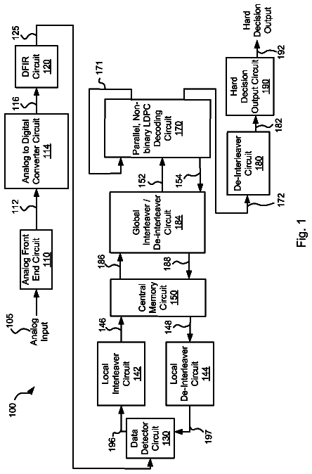
Turning to FIG. 2, a data processing circuit 200 is shown that includes a non-binary LDPC decoder with low latency scheduling 240 that is operable to decode received codewords in accordance with one or more embodiments of the present inventions. Data processing circuit 200 includes an analog front end circuit 202 that receives an analog signal 204. Analog front end circuit 202 processes analog signal 204 and provides a processed analog signal 206 to an analog to digital converter circuit 210. Analog front end circuit 202 may include, but is not limited to, an analog filter and an amplifier circuit as are known in the art. Based upon the disclosure provided herein, one of ordinary skill in the art will recognize a variety of circuitry that may be included as part of analog front end circuit 202. In some cases, analog signal 204 is derived from a read/write head assembly (not shown) that is disposed in relation to a storage medium (not shown). In other cases, analog signal 204 is derived from a receiver circuit (not shown) that is operable to receive a signal from a transmission medium (not shown). The transmission medium may be wired or wireless. Based upon the disclosure provided herein, one of ordinary skill in the art will recognize a variety of source from which analog input 204 may be derived.
Analog to digital converter circuit 210 converts processed analog signal 206 into a corresponding series of digital samples 212. Analog to digital converter circuit 210 may be any circuit known in the art that is capable of producing digital samples corresponding to an analog input signal. Based upon the disclosure provided herein, one of ordinary skill in the art will recognize a variety of analog to digital converter circuits that may be used in relation to different embodiments of the present invention. Digital samples 212 are provided to an equalizer circuit 214. Equalizer circuit 214 applies an equalization algorithm to digital samples 212 to yield an equalized output 216. In some embodiments of the present invention, equalizer circuit 214 is a digital finite impulse response filter circuit as are known in the art. In some cases, equalizer 214 includes sufficient memory to maintain one or more codewords until a data detector circuit 220 is available for processing. It may be possible that equalized output 216 may be received directly from a storage device in, for example, a solid state storage system. In such cases, analog front end circuit 202, analog to digital converter circuit 210 and equalizer circuit 214 may be eliminated where the data is received as a digital data input.
Data detector circuit 220 is operable to apply a data detection algorithm to a received codeword or data set, and in some cases data detector circuit 220 can process two or more codewords in parallel. In some embodiments of the present invention, data detector circuit 220 is a Viterbi algorithm data detector circuit as is known in the art. In other embodiments of the present invention, data detector circuit 220 is a maximum a posteriori data detector circuit as is known in the art. Of note, the general phrases "Viterbi data detection algorithm" or "Viterbi algorithm data detector circuit" are used in their broadest sense to mean any Viterbi detection algorithm or Viterbi algorithm detector circuit or variations thereof including, but not limited to, bi-direction Viterbi detection algorithm or bi-direction Viterbi algorithm detector circuit. Also, the general phrases "maximum a posteriori data detection algorithm" or "maximum a posteriori data detector circuit" are used in their broadest sense to mean any maximum a posteriori detection algorithm or detector circuit or variations thereof including, but not limited to, simplified maximum a posteriori data detection algorithm and a max-log maximum a posteriori data detection algorithm, or corresponding detector circuits. Based upon the disclosure provided herein, one of ordinary skill in the art will recognize a variety of data detector circuits that may be used in relation to different embodiments of the present invention. Data detector circuit 220 is started based upon availability of a data set from equalizer circuit 214 or from a central memory circuit 230.
Upon completion, data detector circuit 220 provides detector output 222. Detector output 222 includes soft data. As used herein, the phrase "soft data" is used in its broadest sense to mean reliability data with each instance of the reliability data indicating a likelihood that a corresponding bit position or group of bit positions has been correctly detected. In some embodiments of the present invention, the soft data or reliability data is log likelihood ratio data as is known in the art. Detected output 222 is provided to a local interleaver circuit 224. Local interleaver circuit 224 is operable to shuffle sub-portions (i.e., local chunks) of the data set included as detected output 222 and provides an interleaved codeword 226 that is stored to central memory circuit 230. Interleaver circuit 224 may be any circuit known in the art that is capable of shuffling data sets to yield a re-arranged data set. Interleaved codeword 226 is stored to central memory circuit 230.
Once non-binary LDPC decoder with low latency scheduling 240 is available, a previously stored interleaved codeword 226 is accessed from central memory circuit 230 as a stored codeword 232 and globally interleaved by a global interleaver/de-interleaver circuit 234. Global interleaver/De-interleaver circuit 234 may be any circuit known in the art that is capable of globally rearranging codewords. Global interleaver/De-interleaver circuit 234 provides a decoder input 236 into non-binary LDPC decoder with low latency scheduling 240. In some embodiments of the present invention, the data decode algorithm is a non-binary non-layer min-sum based low density parity check algorithm. Based upon the disclosure provided herein, one of ordinary skill in the art will recognize other decode algorithms that may be used in relation to different embodiments of the present invention. The non-binary LDPC decoder with low latency scheduling 240 may be implemented similar to that described below in relation to FIGS. 3-5. The non-binary LDPC decoder with low latency scheduling 240 applies a data decode algorithm to decoder input 236 in a variable number of local iterations.
Where the non-binary LDPC decoder with low latency scheduling 240 fails to converge (i.e., fails to yield the originally written data set) and a number of local iterations through non-binary LDPC decoder with low latency scheduling 240 exceeds a threshold, the resulting decoded output is provided as a decoded output 242 back to central memory circuit 230 where it is stored awaiting another global iteration through data detector circuit 220 and non-binary LDPC decoder with low latency scheduling 240. Prior to storage of decoded output 242 to central memory circuit 230, decoded output 242 is globally de-interleaved to yield a globally de-interleaved output 244 that is stored to central memory circuit 230. The global de-interleaving reverses the global interleaving earlier applied to stored codeword 232 to yield decoder input 236. Once data detector circuit 220 is available, a previously stored de-interleaved output 244 is accessed from central memory circuit 230 and locally de-interleaved by a de-interleaver circuit 246. De-interleaver circuit 246 re-arranges decoder output 250 to reverse the shuffling originally performed by interleaver circuit 224. A resulting de-interleaved output 252 is provided to data detector circuit 220 where it is used to guide subsequent detection of a corresponding data set received as equalized output 216.
Alternatively, where the decoded output converges (i.e., yields the originally written data set) in the non-binary LDPC decoder with low latency scheduling 240, the resulting decoded output is provided as an output codeword 254 to a de-interleaver circuit 256. De-interleaver circuit 256 rearranges the data to reverse both the global and local interleaving applied to the data to yield a de-interleaved output 260. De-interleaved output 260 is provided to a hard decision output circuit 262. Hard decision output circuit 262 is operable to re-order data sets that may complete out of order back into their original order. The originally ordered data sets are then provided as a hard decision output 264.
In a conventional non-binary min-sum LDPC decoder with GF(q) and with p check node rows in the parity check matrix, check node processing involves both forward and backward recursions that incur long latency since they require about q.sup.2 additions and comparisons in each of p-2 basic steps. To perform both forward and backward recursions, numerous intermediate messages are stored, requiring a large memory, and messages are sorted when combining the results of forward and backward recursions. In contrast, the min-sum based decoding of non-binary LDPC codes disclosed herein provides low-complexity decoding that does not require forward and backward recursions, sorting or dynamic programming. By including message normalization and modification of the search space, searching over various local configurations is reduced to the simple recursive processing of a single message vector.
Check nodes (implemented in a check node processor or check node unit CNU) in a min-sum based non-binary LDPC decoder receive incoming messages from connected or neighboring variable nodes and generate outgoing messages to each neighboring variable node to implement the parity check matrix for the LDPC code, an example of which is graphically illustrated in the Tanner graph of FIG. 1. Incoming messages to check nodes are also referred to herein as V2C messages, indicating that they flow from variable nodes to check nodes, and outgoing messages from check nodes are also referred to herein as C2V messages, indicating that they flow from check nodes to variable nodes. The check node uses multiple V2C messages to generate an individualized C2V message for each neighboring variable node.
Both V2C and C2V messages are vectors, each including a number of sub-messages with LLR values. Each V2C message vector from a particular variable node will contain sub-messages corresponding to each symbol in the Galois Field, with each sub-message giving the likelihood that the variable node contains that particular symbol. For example, given a Galois Field GF(q) with q elements, V2C and C2V messages will include at least q sub-messages representing the likelihood for each symbol in the field. Message normalization in the simplified min-sum decoding is performed with respect to the most likely symbol. Thus, the V2C and C2V vector format includes two parts, an identification of the most likely symbol and the LLR for the other q-1 symbols, since the most likely symbol has LLR equal to 0 after normalization.
Generally, the C2V vector message from a check node to a variable node contains the probabilities for each symbol d in the Galois Field that the destination variable node contains that symbol d, based on the prior round V2C messages from neighboring variable nodes other than the destination variable node. The inputs from neighboring variable nodes used in a check node to generate the C2V message for a particular neighboring variable node are referred to as extrinsic inputs and include the prior round V2C messages from all neighboring variable nodes except the particular neighboring variable node for which the C2V message is being prepared, in order to avoid positive feedback. The check node thus prepares a different C2V message for each neighboring variable node, using the different set of extrinsic inputs for each message based on the destination variable node.
In the simplified min-sum based decoding applied in some embodiments of the non-binary LDPC decoder with low latency scheduling disclosed herein, the check nodes calculate the minimum sub-message min.sub.1(d), the index idx(d) of min.sub.1(d), and the sub-minimum sub-message min.sub.2(d), or minimum of all sub-messages excluding min.sub.1(d), for each nonzero symbol d in the Galois Field based on all extrinsic V2C messages from neighboring variable nodes. In other words, the sub-messages for a particular symbol d are gathered from messages from all extrinsic inputs, and the min.sub.1(d), idx(d) and min.sub.2(d) is calculated based on the gathered sub-messages for that symbol d. For a Galois Field with q symbols, the check node will calculate the min.sub.1(d), idx(d) and min.sub.2(d) sub-message for each of the q-1 non-zero symbols in the field except the most likely symbol. The min.sub.1(d), idx(d) and min.sub.2(d) values are stored in a memory for use in calculating the C2V message, requiring much less memory than the traditional non-binary LDPC check node processor that stores each intermediate forward and backward message. Such a min-sum based non-binary LDPC decoder, in which the low latency scheduling disclosed herein may be applied, may decode data as disclosed in U.S. patent application Ser. No. 13/180,495, filed Jul. 11, 2011 for a "Min-Sum Based Non-Binary LDPC Decoder", which is incorporated herein for all purposes.
Turning to FIG. 3, a non-binary LDPC decoder with low latency scheduling 300 is shown in accordance with various embodiments of the present inventions, applying the simplified min-sum based decoding disclosed above. Again, it is important to note that the non-binary LDPC decoder with low latency scheduling 300 is not limited to use with min-sum based decoding or to any particular LDPC decoding algorithm. The non-binary LDPC decoder with low latency scheduling 300 may be used in place of LDPC decoder 240 of FIG. 2.
The non-binary LDPC decoder with low latency scheduling 300 is provided with LLR values from an input channel 302, which may be stored in an LLR memory 304. The values are provided to the variable node processor or variable node unit (VNU) 306, which updates the perceived value of symbols based on the value from input channel 302 and on C2V message vectors 310. The VNU 306 yields an external LLR output 312, which may include a hard decision along with soft data, which may be processed in a de-interleaver circuit (e.g., 256) and a hard decision output circuit (e.g., 262) to generate a hard decision output from a data processing system. The VNU 306 also yields a decision output 314 that is provided to a parity calculation circuit 316 to generate a parity check output 320. For example, parity calculation circuit 316 may include multiplexers and XOR circuits to calculate parity check equation .nu.H.sup.T=0 over GF(q), where .nu..epsilon. GF(q).sup.N, and where .nu. is a codeword vector and H.sup.T is the transform of the H matrix for the LDPC decoder.
The VNU 306 performs an update function, adding C2V message vectors 310 to symbol values, and generates V2C message vectors 322 setting forth the updated likelihood for each element in the Galois Field for each symbol in the data set. The V2C message vectors 322 in some embodiments contains a hard decision, an indication of the most likely GF element, and LLR values for the remaining GF elements for each symbol, with the LLR values normalized to the hard decision. For example, the VNU 306 or an external sorting and normalization circuit (not shown) takes the four LLR data values from each symbol, identifies the highest LLR data value of the four values, and normalizes the four LLR data values to the value of the highest LLR data value. An example of this is shown using the following example symbol:
TABLE-US-00001 Hard Decision 00 01 10 11 LLR Data Value 10 15 22 6
In this example, the VNU 306 or external sorting and normalization circuit selects the LLR data value `22` corresponding to the hard decision `10`. Next, the LLR data values corresponding to hard decision values `00`, `01`, `10` and `11` are normalized to LLR data value `22` by subtracting `22` from each of the LLR data values to yield the following normalized symbol:
TABLE-US-00002 Hard Decision 00 01 10 11 Normalized LLR Data Value -12 -7 0 -16
The LLR values may also be scaled in VNU 306 or in an external scaling circuit (not shown), multiplying each of the normalized LLR data values by a scaling factor. The scaling factor may be user programmable. As an example, with a scaling factor of 0.5, the V2C message vectors 322 might include the following scaled symbol based on the current example:
TABLE-US-00003 Hard Decision 00 01 10 11 Normalized LLR Data Value -6 -4 0 -8
The V2C message vectors 322 are provided to a barrel shifter 324. In some embodiments, the code structure of the codeword provided at input channel 302 has a code structure matrix of the following form:
##EQU00002## .times..times..times. ##EQU00002.2##
where each of P.sub.I,J are pxp circulants with weight 1, or permutations of the identity matrix, and the circulant size L is the row weight. The following is an example of a pxp circulant representative of P.sub.I,J:
.alpha..alpha. .alpha..alpha. ##EQU00003##
The barrel shifter 324 is operable to shift the currently received circulant to an identity matrix. Such an identity matrix may be as follows:
.alpha..alpha. .alpha. ##EQU00004##
Barrel shifter 324 provides shifted outputs 326 and 330, where shifted output 326 contains the magnitude and sign of the hard decision HD, and shifted output 330 contains the magnitudes of the remaining LLR values, normalized to the hard decision HD. The shifted output 326 is provided to a sign calculation circuit 332 which calculates the accumulative sign for the hard decisions in shifted output 326, storing the resulting sign value of each non-zero element of the H matrix in a sign FIFO memory 334.
The shifted output 330 is provided to CNU 340, which calculates the first minimum LLR value or sub-message min.sub.1(d), (i.e., the lowest LLR value), the index idx(d) of min.sub.1(d) (i.e., the location in the row corresponding to the first minimum LLR data value), and the second minimum LLR value or sub-message min.sub.2(d), (i.e., the second lowest LLR value) or minimum of all sub-messages excluding min.sub.1(d), for each nonzero symbol din the Galois Field based on all extrinsic V2C messages. In other words, the sub-messages for a particular symbol d are gathered from messages from all extrinsic inputs, and the min.sub.1(d), idx(d) and min.sub.2(d) is calculated based on the gathered sub-messages for that symbol d. For a Galois Field with q symbols, the check node will calculate the min.sub.1(d), idx(d) and min.sub.2(d) sub-message for each of the q-1 non-zero symbols in the field except the most likely symbol, the hard decision HD. Such a simplified min-sum based CNU 340 is referred to herein as a compression circuit. The CNU 340 selects as output 342 either the min.sub.1(d) or min.sub.2(d) to be used in the C2V message such that only extrinsic values are selected. If the current column index is equal to the index of the minimum value, meaning that the C2V message is being prepared for a variable node that provided the min.sub.1(d) value, then the value of the C2V message is the second minimum value min.sub.2(d). Otherwise, the value of the C2V message is the first minimum value min.sub.1(d). With a code structure matrix having three rows, the CNU 340 or external buffer (not shown) would store three sets of first minimum LLR data value, second minimum LLR data value, index value as shown in the example below:
TABLE-US-00004 Row 1 First Minimum LLR Value Second Minimum LLR Value Index Value Row 2 First Minimum LLR Value Second Minimum LLR Value Index Value Row 3 First Minimum LLR Value Second Minimum LLR Value Index Value
The hard decision HD and sign to be used in the C2V message is provided at the output 344 of sign calculation circuit 332, with the sign calculated as the XOR of the cumulative sign and the current sign of the symbol. The output 344 of sign calculation circuit 332 and the output 342 of CNU 340 are provided to barrel shifters 350 and 352, respectively, which shift the C2V message values in output 342 and the hard decisions and their signs in output 344 to yield shifted C2V message values 354 and shifted hard decisions and signs 366, respectively, shifting between circulant sub-matrices. The shifted C2V message values 354 and shifted hard decisions and signs 366 are combined and processed in a combining circuit 370 to yield C2V message vectors 310. The combining circuit 370 is also referred to herein as a check node update and data decompression circuit, and reassembles rows to yield an approximation of the original data.
As will be disclosed in more detail below, a scheduler 380 controls the operation of the VNU 306 and CNU 340, scheduling when they perform the variable node updates and check node updates for each local iteration of data through the non-binary LDPC decoder with low latency scheduling 300. The term "local iteration" is used herein to refer to the processing of a block of data within the non-binary LDPC decoder with low latency scheduling 300, including passing V2C messages from VNU 306 to CNU 340 and C2V messages from CNU 340 to VNU 306, and performing variable node and check node updates in the VNU 306 and CNU 340. The scheduler 380 may comprise circuitry such as logic gates and/or state machines or firmware or other devices to detect when the VNU and CNU complete iterations. The scheduler 380 may also comprise circuitry, firmware or other devices to select C2V messages to be used by the VNU in performing VNU updates and generating V2C messages, for example switching between C2V messages from various iterations when performing VNU updates for a given iteration as the CNU completes an iteration. Based upon the disclosure provided herein, one of ordinary skill in the art will recognize a variety of circuitry or other devices that may be included as part of scheduler 380. The functions disclosed herein relating to scheduler 380 may be performed by a single device external to the VNU and CNU, or the functions may be distributed across multiple devices or fully or partially integrated into the VNU and/or CNU.
FIG. 4 shows a check node update and data decompression circuit 400 that may be used to perform the check node updating and data decompression of combining circuit 370. Decompression circuit 400 includes a first row memory 410 that stores a current and previous set of first minimum LLR data value (Min11), second minimum LLR data value (Min12), index value (index1), and hard decision values received from CNU 340 and sign calculation circuit 332. Similarly, decompression circuit 400 includes a second row memory 420 that stores a current and previous set of first minimum LLR data value (Min21), second minimum LLR data value (Min22), index value (index2), and hard decision values received from CNU 340 and sign calculation circuit 332, and decompression circuit 400 includes a third row memory 430 that stores a current and previous set of first minimum LLR data value (Min31), second minimum LLR data value (Min32), index value (index3), and hard decision values received from CNU 340 and sign calculation circuit 332. The current and previous data is provided from first row memory 410 to a comparison circuit 440 as an output 412, the current and previous data is provided from second row memory 420 to comparison circuit 440 as an output 422, and the current and previous data is provided from third row memory 430 to comparison circuit 440 as an output 432. Comparison circuit 440 determines the elements of the reconstructed approximate values. In particular, comparison circuit 440 provides current and previous data for the first row as a current and previous first row de-compressed output 442, current and previous data for the second row as a current and previous second row de-compressed output 444, current and previous data for the second row as a current and previous second row de-compressed output 446.
In operation, the data is received by comparison circuit 440 one symbol from each row at a time (i.e., three symbols at a time). The index value (CI) for the currently received symbol of output 412, output 422 and output 432 is compared with the index values corresponding to the first minimum LLR data value for row one (index1), the first minimum LLR data value for row two (index2), and the first minimum LLR data value for row three (index3) to yield the comparison values: comparison row 1 (CR1), comparison row 2 (CR2) and comparison row 3 (CR3) in accordance with the following pseudocode:
TABLE-US-00005 If (CI == index1) { CR1 = 1 } Else { CR1=0 } If (CI == index2) { CR2 = 1 } Else { CR2=0 } If (CI == index3) { CR3 = 1 } Else { CR3=0 }
These index values are then used to determine the values of current and previous first row de-compressed output 442 (CO1), current and previous second row de-compressed output 444 (CO2), and current and previous second row de-compressed output 446 (CO3) in accordance with the following table:
The description continues in the full USPTO document.
 Lapsed, fee not paid5 drawings