 Lapsed, fee not paid11 drawings
Hardware & Electronics · US 8,774,428 B2
Very low power MEMS microphone
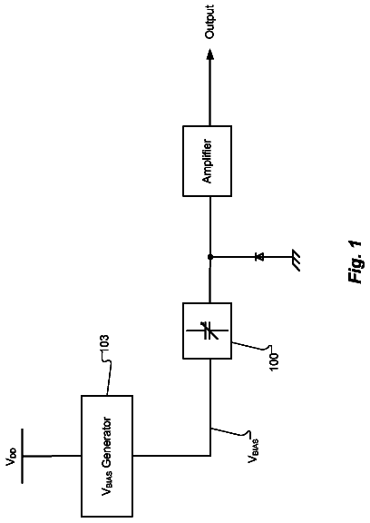
A MEMS microphone is capable of operating with less-than-one-volt bias voltage.
US 8,774,435 B2 · Assignee: Asius Technologies, LLC · Inventors: Ambrose; Stephen D. et al.
Sheet 1 of 37 from the published document. All sheets in the USPTO PDF
A device and method for alleviating the effects of alternating or changing pneumatic pressures when sound is transmitted through an audio device into a substantially trapped volume to the tympanic membrane. Alternating or changing pneumatic pressures are partially or fully alleviated and allowed to remain as normal sound waves. The audio device and method could be any number of audio devices including ear buds, over-ear headphones or hearing aids. A passageway from the substantially trapped volume to an unsealed space at ambient pressure is blocked by a flexible compliant member.
With the invention of the professional in-ear, stage and studio, monitoring systems in the 1970's, large numbers of people began to experience the sealing of high fidelity speakers to the ear canal for the first time. These devices have protected hundreds of thousands of amateur and professional musicians and sound engineers from hearing loss due to excessive performance volumes. However, in-ear monitors have been, and remain, a persistent source of audio fatigue and potential short term or long term hearing loss. They share this problem with other in-ear listening devices such as hearing aids, insert headphones, ear buds, and the like, as well as over-ear devices. Professional applications of in-ear monitors have called for some musicians and sound engineers to tolerate conditions of persistent audio fatigue which can become nearly intolerable by the end of a performance or recording se
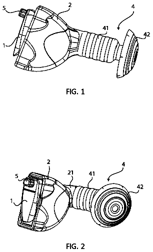
1 of 37 drawing sheets so far from the published document, cropped to the drawing. Every sheet is in the USPTO PDF.
What the patent claimed, word for word. All of it is now free to use.
Independent claims stand on their own. The others add detail to the claim they name.
The present device, system and methods relate to the structure, operation and manufacture of an insertable sound transmission instrument for a user's ear. Specifically, the device and methods relate to such a sound delivery instrument which can be coupled with any number of electronic sound devices, such as a hearing aid, MP3 player, Bluetooth.RTM. device, computer, phone, and the like, while providing improved comfort and control to the user.
With the invention of the professional in-ear, stage and studio, monitoring systems in the 1970's, large numbers of people began to experience the sealing of high fidelity speakers to the ear canal for the first time. These devices have protected hundreds of thousands of amateur and professional musicians and sound engineers from hearing loss due to excessive performance volumes. However, in-ear monitors have been, and remain, a persistent source of audio fatigue and potential short term or long term hearing loss. They share this problem with other in-ear listening devices such as hearing aids, insert headphones, ear buds, and the like, as well as over-ear devices. Professional applications of in-ear monitors have called for some musicians and sound engineers to tolerate conditions of persistent audio fatigue which can become nearly intolerable by the end of a performance or recording session. These users often refer to a sensation of percussiveness beating their ears, which cannot be eliminated by simply turning down the volume. The device, system and methods disclosed herein shed light on the nature of this percussiveness, and discloses inventive measures to mitigate it.
Almost every person has experienced a situation where the volume from another person's headphones could be heard even from across a room, on a bus, in a store, or any number of public venues. Given the sound volume necessary to be heard at a distance, the volume blasting directly into a listener's ear in such a situation must be excessive. The listener might be asked (or admonished) to turn down their headphones for the sake of their own health and for the courtesy to others, but what has not been hitherto widely realized is that the person listening to the headphones has already, unknowingly turned down their own personal perception of the volume through a natural hearing protection mechanism known as the "Stapedius reflex." The persistent triggering of this reflex by insert headphones, hearing aids, and the like, perpetuates a vicious cycle in which even more volume may be needed to counteract the effects of the stapedius reflex.
The persistent triggering of the stapedius reflex also sets up an additional dangerous situation: i.e., the listener, who is already tolerating very loud volumes because of the stapedius reflex, accidentally or intentionally turns the volume up even more. At this point the stapedius muscle may already have become exhausted or reached a limit of its inherent ability to protect the ear from loud sounds and temporary or even permanent hearing loss.
The following is an extensive introduction explaining the scientific basis for the previously unrealized fact that audio speakers when inserted into the human ear produce large oscillations in pressure within the ear canal, even when the speakers are operated at what would normally be considered modest outputs. These large pressures in the sealed volume of the ear canal translate into high sound pressure levels that trigger the Stapedius Reflex. The Stapedius Reflex is a natural mechanism by which the contraction of the stapedius muscle in the ear reduces the ear's sensitivity in order to protect itself from being damaged by loud noises and to widen its dynamic range to higher sound pressure levels. The resulting reduction in hearing sensitivity has the potential to diminish the quality of audio perception through insert headphones or hearing aids.
It will be shown that the acoustic, standing waves produced from a speaker in the ear canal are physically and mathematically equivalent to a static pressure, akin to the air pressure confined within an inflated balloon or the static pressure employed in tympanometry. The magnitude of this static pressure in the sealed ear canal is, unlike the static pressures normally encountered, oscillating at acoustic frequencies. This oscillating static pressure results from the trapping of a closed volume of air in the ear canal when the sound producing device is sealed in the ear. The oscillating static pressure is responsible for gross over-excursions of the tympanic membrane (ear drum) that can be one hundred, one thousand or more times greater than the normal oscillations of the ear drum associated with sound transmitted through the open air.
When sealed in the ear, the motion of the speaker diaphragm produces a set of static pressure oscillations, which are 90 degrees out of phase with equivalent open air sound waves. These static pressure oscillations in the sealed ear canal are also 90 degrees out of phase with the oscillating particle-velocity component of the waves, whereas they would be in phase with the velocity component were the waves occurring in open air. Especially at lower and midrange frequencies, the static pressure oscillations in the sealed ear canal produce a large boost in the sound volume transmitted to the tympanic membrane. Just as the open-air acoustical wave spectrum can contain the superposition of different sound waves at different frequencies, the corresponding static pressure oscillations in a sealed volume, such as the ear canal, superpose to form a spectrum of co-existing static pressure oscillations with a range of frequencies.
The large amplitude static pressure oscillations, typically associated with the lower frequency and/or greatest amplitude motions of the speaker produce an effect, which we will call Trapped Volume Insertion Gain (TVIG). TVIG is related to insertion gain as measured and used by the audio and hearing aid industries. TVIG is defined as the increase in sound pressure level (SPL), resulting from the static pressure oscillations in the ear canal across all frequencies, occurs when a speaker containing device is sealed in the ear. It is measured relative to the SPL in the ear canal when the device is held in approximately the same position at the entrance to the ear canal, but is not sealed with an air-tight seal. In this unsealed reference state, the sound waves in the ear are not equivalent to static pressures. It is shown herein that the trapped volume insertion gain of insert headphones or hearing aids is often sufficient to boost the SPL experienced by the listener above the threshold at which the stapedius reflex reduces hearing sensitivity.
It seems particularly counter-productive to have devices intended to provide high fidelity audio (insert headphones, ear buds, etc.), or aid to the hearing impaired (hearing aids) that simultaneously reduce hearing sensitivity by triggering the stapedius reflex. It is possible that trapped volume insertion gain, which is operating continuously as long as the device is sealed in the ear canal, causes the stapedius muscle to remain in a continuously clenched state. This is not a normal condition for the stapedius muscle, and it significantly contributes to and may even be the main cause of listener fatigue, in which peoples' ears begin to physically ache or hurt after prolonged use of in-ear devices.
The gross over-excursions of the tympanic membrane, produced by sealing a sound producing device in the ear, occur despite the best efforts of the clenched stapedius muscle to limit their amplitude. The trapped volume pressure, and trapped volume insertion gain, along with their influence on the stapedius reflex, have not been widely appreciated or acknowledged by audio science or industry. And, as such, their potential long term damaging impacts on human hearing have not been studied. It is hypothesized that the pressure-driven pounding may also contribute to hearing damage that popular opinion and recent study attribute to the use of in-ear listening devices.
The present application addresses the need for an in-ear listening device to lessen the impact of tympanic membrane over-excursions, oscillating static pressure in the ear canal, trapped volume insertion gain, and the constant triggering of the stapedius reflex. The inventive technology disclosed is applicable to ear buds, headphones, hearing aids, Bluetooth headsets and the like. The technology mitigates the detrimental effects of sealing a sound producing device in the ear canal by the use of an inflatable in-ear bubble-seal of the type claimed in our previous patent applications. Additionally, this application discloses a new inventive approach and a family of resultant devices that achieve the mitigation of trapped volume insertion gain, oscillating static pressure, tympanic membrane over-excursions, and the stapedius reflex in a simple and potentially inexpensive retrofit to existing in-ear devices. Both the inflatable ear seals, and the retrofit devices operate to at least partially transform the sound energy in the trapped volume in the ear canal from an oscillating static pressure back into a normal acoustic wave, which is lower in amplitude and less punishing in its effects on the ear drum, the stapedius muscle, and the ear in general.
1.1 Sound Waves in Open Air
Sound waves in open air propagate through alternating rarefactions and densifications of the gas molecules comprising the air. The propagation of sound, however, does not change the average density of the air. At any instant in time, higher pressure in densified sound wave maxima are compensated by lower pressure in rarified sound wave minima. Overall, the average air pressure remains the same. Additionally, the magnitude of sound pressure fluctuations in the open air are tiny: for instance a 100 dB sound pressure level (SPL) in air at atmospheric conditions is accompanied by a fluctuating pressure amplitude of about 5 Pa (rms average), while the atmospheric pressure itself is 101,000 Pa. Thus, this relatively loud sound is transported through air via a pressure fluctuation about twenty-thousand times smaller than the static pressure of the air itself. When a person hears sound transmitted to their open ear, through open air, these tiny, acoustic pressure fluctuations drive the motion of the tympanic membrane, and these motions are correspondingly tiny, on the order of tens to hundreds of nanometers.
1.2 Sound Generation in Open Air
When a vibrating surface (such as a speaker diaphragm) is the source of sound waves in open air, the amplitude of the oscillating pressure wave that results (i.e. the loudness) is directly proportional to the maximum transverse velocity of the surface. As with any harmonic motion, this maximum velocity occurs at the mid-point of the surface's oscillation, where displacement is zero and speed is greatest. Thus the loudness of sound from a speaker in open air is determined by how rapidly the surface can be made to move at its fastest point, not by the total amplitude of the excursions of the surface. Of course, as sound volume increases, the amplitude of speaker motion can be seen to obviously increase. In fact, for a sinusoidal profile of speaker displacement vs. time, the maximum speed of speaker motion can easily be shown to be equal to .omega.L, where .omega. is the angular frequency (2.pi. time frequency) and L is the maximum extent of the speaker motion. This is a secondary effect, however; these large excursions are not directly responsible for the increase in sound volume. The speaker surface and its underlying electromagnetic drive are physical objects with mass and inertia, and therefore greater speed requires more distance to accelerate, and then to slow down and reverse direction at the extremes (greatest amplitude and zero velocity) of the cyclical motion. Clearly the amplitude or distance of the speaker motion, L, is not responsible for sound generation since a surface can move slowly over large distances (like picking up a speaker and carrying it across a room) without creating sound waves.
2. Speaker Sealed in the Ear Canal
When a speaker is sealed in the ear canal, creating a small trapped volume of air, the familiar physics of sound generation and sound propagation in open air is altered dramatically. If the length of this trapped volume in the ear canal is taken to be about 1 cm or less (values vary by individuals and with the type of device and depth of insertion in the ear), FIG. 1 shows the length of the trapped volume as a fraction of the wavelength of sound across the frequency range. Especially for low frequencies, but extending up into the mid-range, the trapped volume in the ear canal is only a small fraction of the wavelength of the sound.
Within this small trapped volume, only a tiny snippet at a time of an oscillating pressure profile (what would be a normal sound wave in open air) can exist. Especially for lows and mid-range frequencies, the pressure across this small trapped volume is very nearly constant because the ear canal is only sampling a small section of the "wave" at a given instant. As a result of the fact that pressure maxima can no longer coexist in time with pressure minima (as they do in open air sound waves) the average static air pressure of the system is no longer constrained to remain constant (as it is for sound wave propagation in open air). In fact, the overall pressure in the trapped volume of the ear canal can oscillate dramatically, and this results in excursions of the tympanic membrane that are orders of magnitude larger than in normal, open-ear listening.
We refer to this pressure, caused by a sealed speaker in the ear canal, as a static pressure. One reason for doing so is that this pressure bears some similarity in its effect on the ear to the static pressure applied in the diagnostic technique of tympanometry. In tympanometry, the ear canal is sealed with an insert headphone and air is pumped in and out of the sealed volume to both increase and reduce the pressure in the sealed volume relative to atmospheric pressure (and the pressure in the middle ear). This pressurization of the ear canal in tympanometry is referred to as static pressure, to distinguish it from the SPL employed in the technique, which is oscillating at acoustical frequencies, and is generally of much lower magnitude. Tellingly, it is known that the application of static pressure in the ear canal, during tympanometry can trigger the stapedius reflex. This is a non-acoustical triggering of the reflex, which must come about due to the large excursion of the tympanic membrane resulting from the pressure difference between the ear canal and the middle ear, rather than expose to a threshold SPL level. As discussed below, the static pressure induced when a headset or hearing aid with a speaker is sealed in the ear canal, has a dual character. It is simultaneously a static pressure, like the pressure produced by pumping air into the ear canal in tympanometry, and an oscillating sound pressure which can be measured as SPL. It can, therefore, potentially trigger the stapedius reflex both by its acoustical SPL and by the magnitude of its static pressure.
The static pressure in the ear canal is the pressure that results from a change in the volume (a compression or rarefaction) of a fixed amount of air trapped in the ear canal. This static pressure may, at any instant, be greater than, equal to, or less than the barometric pressure outside the ear. The static pressure may be changing (oscillating) rapidly, and thus the use of the term static may seem strange. However, the term static refers to the fact that this pressure is not a transient oscillation in pressure (i.e. a sound wave in open air) but rather is a thermodynamic, equilibrium property of the air mass associated with its volume. If the volume of this fixed mass of air is held constant (i.e. the speaker diaphragm is frozen at any point of its motion) then the static pressure will remain constant. If the volume of this air mass is changing or oscillating with the speaker motion then this thermodynamic, equilibrium property (static pressure) will also be changing or oscillating. This is true of the static pressure oscillations produced by a speaker sealed in the ear canal, provided that the rate at which pressure equilibrium is established at every incremental position of the moving speaker diaphragm is much faster than the motion of the diaphragm. The static pressure equilibrates via molecular motions that propagate across the 1 cm length of the trapped volume at the speed of sound. FIG. 2 plots the ratio of the speed of pressure equilibration vs. the peak speed of speaker motion across the frequency range. Clearly, the equilibration of pressure is much faster (thousands to hundreds of thousands of times faster) than the change in pressure resulting from speaker motion, and thus the pressure is at quasi-equilibrium, at any given instant, with respect to the influence of the moving speaker diaphragm, especially at lower frequencies.
2.1 Classical Acoustic Analysis
Beranek, analyzed case of a rigid piston oscillating in one end of a rigid tube, which is closed on the opposite end (Leo L. Beranek, Acoustics (New York: McGraw-Hill, 1954) Section 2.4, pp. 28-35). FIG. 2.3 of the Beranek reference reproduced as FIG. 3.
The analysis focuses mainly on tubes, which are long enough to set up standing wave patterns with various locations of increased and decreased pressure along the tube. However, Beranek's Equations 2.47 and 2.48 (reproduced below), which give the pressure profiles along the length of the tube, are equally applicable to very short tubes, although Beranek, himself, did not explore the implications in his book. Clearly, insert headphones that seal in the ear canal were not around in the 1950's, when Beranek did this work.
.function..times..times..times..times.eI.times..times..times..times..time- s..times..times..times..times..times..times..times..times..times..times..t- imes..times. ##EQU00001##
In these equations u is the piston speed, .rho. is the density of air, c is the speed of sound, l is the tube length, x is the coordinate along the tube from zero at the piston's zero displacement position up to l. k is 2.pi./.lamda., where .lamda. is the wavelength. The "o" subscripts on the u and .rho. values indicate the use of root-mean-square (rms) values and the equations then yield rms pressures. The equations, however, apply equally well to peak valves (drop the subscripts) and then give peak pressure (i.e., amplitude of the pressure oscillations). The term j is an imaginary number, also frequently known as i. Disregarding the i, which has to do with getting the correct phase of the time oscillation, Equation 2.48 gives the amplitude of the resulting pressure wave in the tube as a function of distance x, along the tube.
FIG. 4 shows the pressure profiles along a 1 cm long tube, approximating the length of the sealed, trapped volume in the ear canal calculated from Beranek's equations. The pressures plotted are the ratios of the amplitude (maximum value) of the pressures in the sealed tube divided by the pressure amplitude of the sound waves that the same piston motion would produce in open air. The pressure in the small closed tube is significantly higher than in open air, except at high frequencies. This graph shows that at an instant in time that the pressure is very uniform along the 1 cm length of the tube.
Of course the pressure is also oscillating in time. FIG. 4 shows the profile at the time when pressure is maximum. The pressure profile is equally flat with distance along the tube, but at other pressure levels, at other points in the time oscillation. As the pressure in the tube changes, these changes must propagate across the tube from the moving piston at the speed of sound. The small length of the tube, relative to the wavelength of the oscillations, however, means that the pressure profile across the tube equilibrates at each time much faster than the overall pressure level is changing with time as a result of the piston oscillations. Thus the pressure across the tube can be considered constant at any instant.
The constant pressure amplitudes across the 1 cm sealed tube length, given in FIG. 4 are quite similar to the pressures in the trapped volume of the ear canal calculated for a much more involved model taking into account the compliances and motions of the structures of the middle ear (tympanic membrane, etc.). These more realistic values are plotted in FIG. 17, below. The values in FIG. 4 are a little higher than those in FIG. 17, because the Beranek model is for a completely rigid sealed tube, with no way to mitigate the pressure increase through the motion of its surfaces.
Beranek's model of acoustical waves in a closed, rigid cylinder shows that the pressure waves produced by the oscillating piston, at one end, interfere with waves reflected off the opposite end of the tube. The resultant pressure profile in the tube is the standing wave pattern associated with the interference of this forward and reflected wave. The pressure profiles plotted in FIG. 4, resulting from this model, show that in the case where the tube is a small fraction of the wavelength of the sound, that the standing pressure waves yield a flat pressure profile across the tube. There are no nodes and antinodes of high and low pressure of the type Beranek plots in his FIG. 2.6, if the tube length is very short. The result of the interference of forward and reverse traveling waves in the closed tube also leads to a 90 degree phase shift in the pressure wave relative to the motion of the driving piston. In Beranek's analysis this phase shift is seen to be a result of the interference of a forward and a reverse traveling acoustical wave.
The fact that the pressure profile in the short tube is quasi-static and thus may be analyzed as an oscillating static pressure, rather than as an acoustic wave, can be proved by transforming Beranek's equation 2.48, in the limit of small into an expression, which is the mathematical definition of the pressure vs. volume behavior of a confined volume under static pressure. We start with a simplified version of Beranek's Equation 2.48 for the peak pressure value (pressure amplitude) as a function of distance, x, along the tube. P=.rho.cu cos(k(l-x))/sin(kl) (Equation 1)
We recognize that when l/.lamda. is very small that we can employ the normal approximations to the values of the cosine and sine functions when their arguments are small. The cosine with a very small argument is very close to one, and the sine with a very small argument is well-approximated by the argument itself. The validity of these approximations is the direct mathematical cause of the flatness of the pressure profiles in FIG. 4 for frequencies up to at least 1000 Hz. With these approximations the expression for the pressure becomes: P=.rho.cu/(kl) (Equation 2)
The maximum speed of the piston, u, is equal to .omega..delta., where .delta. is the maximum displacement of the piston. Substituting this into Equation 2, along with the value of k in terms of wavelength, and utilizing the relationship c=.omega..lamda./(2.pi.), one obtains: P=.rho.c.sup.2(.delta./l) (Equation 3)
The total volume of the tube, V, is equal to Sl, where S is the cross-sectional area of the tube. The change in volume of the tube, .DELTA.V, is equal to S.delta.. And, therefore, (.delta./l) is equal to (.DELTA.V/V), the factor of S cancelling out of the numerator and denominator. Additionally, the fundamental definition of the speed of sound in terms of the mass and compliance of the medium in which is traveling is: c.sup.2=B/.rho., where B is the bulk modulus (resistance to change in volume). Therefore: P=B(.DELTA.V/V) (Equation 4)
Equation 4 is the very definition of the pressure vs. volume change properties of a gas undergoing a static pressure compression or rarefaction. This has been derived, starting from an acoustical equation and imposing the limit of small tube length relative to wavelength. This proves that in this limit, we can safely analyze the case of a speaker sealed in the ear canal in terms of its static pressure effects.
A further insight links the reflection of the sound wave at the rigid back wall of the sealed tube, in Beranek's acoustical derivation, with the concept of static pressure. When the piston in the tube moves forward and compresses the gas, the rigid boundary of opposite end of the tube can either be thought of as a wall which limits the volume change of the tube at its far end, and thus enables the piston to produce a .DELTA.V, or it can be considered a hard wall boundary condition, which reflects an acoustical wave and sends a reverse wave back down the tube. The result of either analysis is exactly the same for a small tube length. Therefore, a speaker sealed in ear canal operates like pneumatic piston, producing time oscillations in overall or static pressure (analogous to barometric pressure in open air) in the trapped volume of the ear canal. These static pressure oscillations certainly do move the tympanic membrane.
When the speaker is sealed in the ear canal, the peak oscillating static pressure is determined not by the maximum speaker diaphragm speed (as in the case of open air acoustic waves) but by the maximum speaker excursion, .delta. in Equation 3. This is, in fact, exactly the opposite of the open air operation of the speaker. However, this is also obviously true for the sealed volume case. When a speaker diaphragm moves forward into the trapped volume of the ear canal, it reduces that volume by the product of the speaker area and the distance the speaker is moving. The speed with which this occurs is not important to the static pressure achieved in the trapped volume. But the extent of speaker motion determines the amount of volume reduction, which is directly related to the corresponding static pressure increase by the compressibility of the air (Equation 4). As discussed below, this trapped volume mechanism can lead to static pressures in the ear canal which are much larger (up to hundreds of times larger) than the sound pressures present in open air sound waves. This can trigger the stapedius reflex, thereby reducing the sensitivity of human hearing, and results in strong motions of the tympanic membrane, which are also much larger than those in normal open ear hearing.
An oscillating speaker sealed in the ear canal produces large amplitude, static pressure waves associated with the maximum displacement of speaker motion. However, the acoustical science view of what is happening, as embodied in Beranek's analysis above, indicates that acoustical pressure disturbances are simultaneously being generated and are associated with the maximum speed of the speaker diaphragm. It is the interaction of the forward and reverse traveling acoustical waves that generates the static pressure in the small confined volume, and makes the overall phenomenon appear to be related to speaker displacement and to be 90 degrees out of phase with the speaker velocity. Thus the phenomena occurring in a small trapped volume, such as the ear canal, has a dual character, somewhat akin to the wave-particle dual character of light, and fundamental physical particles. The oscillating pressure effects in the sealed ear canal are both acoustical waves and static pressure oscillations at the same time. Which of these two aspects of the phenomena is dominant, depends on the conditions. For instance, smaller confined volumes and lower frequencies (longer wavelengths) favor an oscillating-static-pressure-like behavior, while larger trapped volumes and higher frequencies favor an acoustical-wave-like behavior.
It would be convenient to define a criteria or parameter that governs whether or not sound waves in a particular medium, at a particular frequency, can be interpreted as an oscillating static pressure in a confined volume of a specific size. The most rigorous test of static pressure character is that the standing wave pressure profile calculated from Beranek's Equation 2.48 (Eqn. 1 herein) is nearly constant at every location, x, along the length of the trapped volume. This profile as calculated from the Equations will never be mathematically, exactly constant due to the nature of the mathematics employed. However, the profile can be considered functionally constant, when the calculated variations in the pressure profile are smaller than what can be measured experimentally, or alternatively are smaller than the random and transient, natural thermal fluctuations in the pressure that are always present in any system. This is equivalent to the condition that kl is very small, which is in turn equivalent to the condition that l/.lamda. is very small. The criterion is expressed as the ratio of the length scale associated with pressure equilibration, l, to the length scale associated with pressure variation, .lamda., due to sound. Exactly the same criterion can also be expressed as the ratio of the time scale of pressure equilibration in trapped volume to the time of sound wave pressure variation, or (l.nu./c). Here .nu. is the frequency.
Experimental and modeling results, to be presented below, indicate that for frequencies below about 100 Hz, a speaker sealed in the ear canal is dominated by static pressure effects, and that for frequencies greater than a few thousand Hz the behavior is predominantly acoustical. In the middle range of frequencies between these two extremes, the static pressure and acoustical behavior overlap and are both evident.
Complex audio material comprising multiple frequencies will result in multiple pressure waves of varying acoustical and static pressure character superposing in the ear canal. The lower frequencies have more of a static pressure oscillation character and the higher frequencies have more of an acoustical character. The result on the tympanic membrane, of all these sound waves, is determined by their summation under the Superposition Principle. It seems likely that the tympanic membrane undergoes large amplitude excursions, due to the oscillating static pressure character of sound waves at low frequency, while at the same time it is undergoing smaller amplitude vibrations at a range of other frequencies as a result of acoustical waves, which are also present in the ear canal.
2.2 Direct Observation of Over-Excursions of the Tympanic Membrane
Gross over-excursions of the tympanic membrane have been directly observed and video of them has been recorded using the device shown in FIG. 5. This device is a modification of a digital, pneumatic, video otoscope, an instrument a doctor uses to look into an ear canal. A commercial Apple iPod ear-bud was sealed into the insufflation port, which is a hole in the side of the device (see FIG. 5b). When the otoscope is inserted tightly into the ear canal (FIG. 5c), it produces a trapped volume and allows the tympanic membrane to be observed and filmed while music or tones are played through the ear-bud. High volume, low frequency sound played through the ear-bud (sounds which were accessed using the volume and frequency capabilities of an Apple.RTM. iPhone.RTM.) produced visible motions of the tympanic membrane, which corresponded in frequency with the output from the earbud. This was particularly discernable at the lowest frequency tested, 2 Hz, in which to tympanic membrane can readily be seen to oscillate twice per second. The same frequencies, at even much higher volumes, would not produce visible motions of the tympanic membrane for open ear hearing. Typical open-ear tympanic membrane motions of tens to hundreds of nanometers are far too small to be visible with an optical microscope. Motions of the tympanic membrane must be at least 10-100 micrometers (or 100 to 1000 times larger than normal tympanic membrane motions) to be visible with the magnifying otoscope.
Another feature that distinguishes oscillating pneumatic pressure in a trapped ear-canal volume from open air sound is directional dependence. Open-air sound, especially at higher frequencies, is louder when it is projected directly at the listener, rather than heard from the side. The transmission of open-air sound around corners is imperfect and becomes worse as frequency increases. Static pressure, of the type generated by a speaker in a sealed ear canal, is not directional. It pushes equally on all surfaces exposed to the pressure regardless of their orientation. This is the same, for instance, as hydrostatic pressure, which pushes equally on all surfaces of an object submerged under water. This difference in directional dependence between sound waves in open air and static pressure oscillations is observable with the modified otoscope device of FIG. 5. The ear-bud on the side of the otoscope is mounted at a right angle to the snout of the otoscope, which is inserted into the ear canal. Thus the ear-bud is not projecting its sound down the ear canal but transverse to the ear canal. When higher, more directionally sensitive, frequencies are played through this ear-bud, there is a marked difference in how they sound when the otoscope is sealed in the ear and when the snout of the otoscope is loosened to break the seal. When the device is not sealed the sound is not as distinct. It becomes louder, but also harsher (more percussive on the tympanic membrane), when the ear canal seal is established.
3. Modeling of a Speaker in a Trapped Ear Canal Volume
3.1 Simple Model
A very simple model, shown in FIG. 6, was analyzed mathematically to get an initial indication of the order of magnitude of responses and the general trends associated with the static pressure effects of sealing a speaker in the ear canal. This model consists of a tube of length and diameter intended to approximate the dimensions of the trapped volume in the ear canal. It is taken to be 7 mm in diameter and the length, L (the same parameter as l used in Beranek), can be varied to simulate different speaker insertion depths resulting in different trapped volume sizes. Tube lengths of 1.0 and 0.5 cm were used for illustrative calculations. One end of the tube is covered by a flexible membrane which can be displaced to simulate the motion of the speaker diaphragm. The other end of the tube is covered by a membrane with an elastic modulus equal to an average value measured for human tympanic membranes: E (Young's Modulus)=3 N/m.sup.2. Both the speaker diaphragm and the tympanic membrane are assumed to have the same diameter as the tube. The pressure outside the sealed tube is initially atmospheric pressure. On the other side of the tympanic membrane is another volume, which simulates that of the middle ear. This middle ear volume is also initially at atmospheric pressure, and it has a volume of 1.5 cm.sup.3, an average value for the human population.
The computational model, as shown in FIG. 6, is very similar to an actual physical model of the ear canal used in recently reported experiments on the acoustics of insert headphones.
When the speaker diaphragm is displaced toward the trapped volume (as a hemispherical deformation), decreasing the volume, the model system distributes the effect of this disturbance between the pressurization of air in the sealed volume of the ear canal and the displacement of the tympanic membrane. The displacement of the tympanic membrane also displaces and pressurizes air in the middle ear cavity. The pressurization of the air in the ear canal and in the middle ear volume is resisted by the compressibility modulus of the air, which is derived from the Ideal Gas Law. The Ideal Gas Law is an excellent representation of the behavior of air at body temperature and near atmospheric pressure, as the compressibility factor (Z) is essentially equal to one. The stretching of the tympanic membrane, due to the pressure differential between the sealed ear canal volume and the middle ear volume, is resisted by the stretching modulus of the tympanic membrane, and is modeled as in Reference. The actual vibrational modes and extensional geometries of the tympanic membrane may be quite complex. They are simpler and more similar to the simple hemispherical deformation model used here, at lower frequencies. This modeling yields a relationship between the displacement of the tympanic membrane and the pressure difference across the membrane. Equating the pressure difference across the tympanic membrane, in terms of the pressures in the ear canal and the middle ear, to the pressure driving force for deformation of the tympanic membrane allows one to solve for both the pressure increase in the trapped volume of the ear canal and extent of deformation of the tympanic membrane.
Calculations based on this simple model were performed for a range of speaker displacements from 1 to 400 microns, and for frequencies ranging from 10 Hz to 1000 Hz. The resulting tympanic membrane displacements and pressure increases in the closed, ear canal volume were calculated. And, the pressure increase in the closed, ear canal volume was compared to the sound pressure in open air that the same speaker motion would generate. In order to perform the open air calculation, the speaker displacement and frequency were used to calculate the maximum diaphragm velocity assuming sinusoidal diaphragm displacement vs. time. Under these conditions the maximum diaphragm velocity is .omega.L.sub.s, where .omega. is the angular frequency equal to 2.pi. time the frequency, and L.sub.s is the amplitude of speaker displacement (similar to .delta. used above in Section 2.1).
FIG. 7 shows the calculated tympanic membrane displacement vs. speaker displacement, for the sealed ear case, with trapped volume lengths of 1 cm and 0.5 cm. Note that there is no frequency dependence of the tympanic membrane displacement since the displacement depends on static pressure, which is related to speaker displacement, not to speaker velocity.
Speaker displacements in the micron range produce static-pressure-driven, tympanic membrane excursions that are also in the micron range, these are 100 to 1000 time the normal tympanic membrane excursion amplitudes, which are tens to hundreds of nanometers. The smaller the trapped volume, the greater the tympanic membrane excursion. This is because the same speaker displacement, relative to a smaller trapped volume, produces a greater pressure increase.
FIG. 8 shows the same tympanic membrane displacement vs. speaker displacement except that the tympanic membrane displacement is shown as a percentage relative to the driving speaker displacement.
At relatively small speaker displacements, the excursions of the tympanic membrane, as predicted by this simple model, are nearly the same as those of the speaker. In this case, the air in the trapped volume is behaving like a piston, which transfers motion from the speaker diaphragm to the tympanic membrane with negligible air compression. This occurs because at relatively small displacements, the tympanic membrane is extremely compliant, and thus it takes less energy to displace the tympanic membrane than to compress the air. However, as the speaker displacements become large, the percentage of this speaker displacement that is transferred to the tympanic membrane drops. This is because the tensile modulus of the tympanic membrane resists extremely large excursions of the tympanic membrane. At these higher speaker excursions the tympanic membrane can only do so much to absorb the compressive energy and some of this must be taken up by compression of the air in the trapped volume.
The description continues in the full USPTO document.
About 6,473 words. The USPTO PDF has it with every drawing.
Fees are due 3.5, 7.5 and 11.5 years after grant. This patent expired on July 8, 2026, so the fee marked "not paid" was the one that went unpaid.
Audio Device, System and Method
Filed Nov 2011 · published Aug 2012Audio device, system and method
Filed Nov 2011 · granted Jul 2014Earlier publications, parents and continuations. None of them can still be enforced, or this patent would not be listed.
Prior art cited by the examiner or applicant. Useful when you check your own idea for novelty.
Everything on this page comes from the documents linked above.