 Lapsed, fee not paid10 drawings
Hardware & Electronics · US 8,774,369 B2
Method and system to provide priority indicating calls
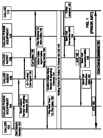
A method implemented to provide voice calls in a network.
US 8,774,380 B2 · Assignee: Verizon Patent and Licensing Inc. · Inventors: Chingon; Robert A et al.
Sheet 1 of 12 from the published document. All sheets in the USPTO PDF
Methods and systems for managing a call in real-time are disclosed. Methods and systems consistent with the present invention manage a call in real-time based on input from a user. A service center receives information pertaining to a call to the user from a service control point and sends a notification of the call to a device associated with the user. The service center receives a response to the notification from the user. Thereafter, the service center instructs the service control point to connect the call based on the response.
A wide variety of means exist for communication between users. For example, a user may conduct phone calls via a home phone, work phone, and mobile phone. In addition, users may also communicate using devices such as PC's, PDA's, pagers, etc. using manners of communicating such as email and instant messaging. Unfortunately, managing such a wide variety of communication means can be difficult. In particular, as a user changes location, communication with the user may vary. For example, while on travel, it may only be possible to reach a user by mobile phone. However, the user may best be reached by email while at work. Also, the user may wish to implement various rules for receiving and controlling communications. For example, to be reached at home, the user may want the home phone to ring three times before forwarding the call to a mobile phone. As another example, the user may wish to b
1 of 12 drawing sheets so far from the published document, cropped to the drawing. Every sheet is in the USPTO PDF.
What the patent claimed, word for word. All of it is now free to use.
The present invention relates generally to data processing systems and, more particularly, to a method and system for managing calls in real-time with user intervention.
A wide variety of means exist for communication between users. For example, a user may conduct phone calls via a home phone, work phone, and mobile phone. In addition, users may also communicate using devices such as PC's, PDA's, pagers, etc. using manners of communicating such as email and instant messaging.
Unfortunately, managing such a wide variety of communication means can be difficult. In particular, as a user changes location, communication with the user may vary. For example, while on travel, it may only be possible to reach a user by mobile phone. However, the user may best be reached by email while at work. Also, the user may wish to implement various rules for receiving and controlling communications. For example, to be reached at home, the user may want the home phone to ring three times before forwarding the call to a mobile phone. As another example, the user may wish to be paged each time an email is received from a particular person while away from the office.
A user may also wish to treat a phone call differently dependent on who is calling the user. For example, if a user receives a call from a caller that the user does not want to speak to at the moment, the user may want to send that call directly to voice mail. Also, if a user receives a call from a number that displays no caller ID information or that the user otherwise does not recognize, the user may wish to somehow specially treat the call because the caller is a potential telemarketer.
Current call management systems make it possible for a user to receive notification of a call on a communications device, and then to either take the call or divert it to voice mail to the user's discretion. Current call management systems also make it possible to automatically intercept and specially treat a call that displays no caller ID information.
Current call management systems, however, do not enable a user to perform other functions as a call is being received, such as forwarding a phone call received on one device to another device, manually initiating protection from telemarketers, or otherwise managing a call in real-time. Accordingly, there is a need for a method and system for a method and system for managing calls in real-time with user intervention.
Methods and systems consistent with the principles of the invention manage a call. A service center receives information pertaining to a call to a customer from a service control point, the service control point being operable to determine how a call is connected. The service center also sends a notification of the call to a device associated with the customer and receives a response to the notification from the customer. Thereafter, the service center instructs the service control point to connect the call based on the response.
Other methods and systems consistent with the principles of the invention also manage a call. A service center receives information pertaining to a call to a customer from a service control point, the service control point being operable to determine how a call is connected. The service center also retrieves data corresponding to the customer using the information pertaining to the call, sends a notification of the call to a device associated with the customer, and receives a response to the notification from the customer. Thereafter, the service center instructs the service control point to connect the call based on the response.
Other methods and systems consistent with the principles of the invention manage a call in real-time based on input from a user. A service center receives information pertaining to a call to the user. The service center also sends a notification of the call to a first device associated with the user and receives a response to the notification from the user. Thereafter, a service control point forwards the call to a second device based on the response. The user provides a telephone number for the second device.
Other methods and systems consistent with the principles of the invention also manage a call in real-time based on input from a user. A service center receives information pertaining to a call to the user. The service center also retrieves data corresponding to the user using the information pertaining to the call and selects a device associated with the user to receive a notification of the call based on the retrieved data corresponding to the user. Additionally, the service center provides the notification to the selected device for display on the selected device and receives a response to the notification from the user. Thereafter, a service control point initiates a call screening process based on the response.
Other methods and systems consistent with the principles of the invention also manage a call. A service center receives information pertaining to a call to a customer from a service control point, the service control point being operable to determine how a call is connected. The service center also retrieves data corresponding to the customer using the information pertaining to the call, determines features enabled for the customer based on the information pertaining to the call, selects a device associated with the customer to receive a notification of the call based on the retrieved data, provides the notification to the selected device, and receives a response to the notification from the customer. Thereafter, the service center instructs the service control point to connect the call based on the response.
Other methods and systems consistent with the principles of the invention also manage a call. A device associated with a customer receives a notification of a call to the customer, wherein the device is determined based on retrieved data corresponding to the customer and the retrieved data was retrieved using information pertaining to the call. The device also receives input from the customer indicative of a response to the notification and sends response information to a server reflective of the response to the notification. Thereafter, the server instructs a service control point to connect the call based on the response to the notification.
Other methods and systems consistent with the principles of the invention also manage a call. A service control point sends information to a service center pertaining to a call to a customer. The service center is operable to retrieve data corresponding to the customer using the information pertaining to the call; send a notification of the call to a device associated with the customer, wherein the device is determined based on the retrieved data, and the device is one of a plurality of devices associated with the customer; and provide response information reflective of a response to the notification from the customer. The service control point receives the response information from the service center and connects the call based on the response information.
The accompanying drawings, which are incorporated in and constitute a part of this specification, illustrate one embodiment of the invention and, together with the description, serve to explain the principles of the invention.
FIG. 1 is a diagram of an exemplary data processing and telecommunications environment in which features and aspects consistent with the principals of the present invention may be implemented;
FIG. 2 is a diagram of an exemplary user terminal, consistent with the principals of the present invention;
FIG. 3 is a diagram of a voice network, consistent with the principles of the present invention;
FIG. 4 is a block diagram of a service center, consistent with the principles of the present invention;
FIG. 5 illustrates a logical architecture of an exemplary system, consistent with the present invention;
FIG. 6 is a diagram of an exemplary network access server consistent with the principles of the present invention;
FIG. 7 is a diagram of an exemplary application server consistent with the principles of the present invention;
FIG. 8 is a diagram of an exemplary flowchart of a method for real-time call management in a manner consistent with the present invention;
FIGS. 9A and 9B comprise another diagram of an exemplary flowchart of a method for real-time call management in a manner consistent with the present invention;
FIG. 10 is a diagram of an exemplary user interface including customer-selectable real-time call management options consistent with the present invention; and
FIG. 11 is a diagram of an exemplary user interface that enables a customer to change preferences consistent with the present invention.
Reference will now be made in detail to exemplary embodiments of the present invention, examples of which are illustrated in the accompanying drawings. Wherever possible, the same reference numbers will be used throughout the drawings to refer to the same or like parts. While the description includes exemplary embodiments, other embodiments are possible, and changes may be made to the embodiments described without departing from the spirit and scope of the invention. The following detailed description does not limit the invention. Instead, the scope of the invention is defined by the appended claims and their equivalents.
Overview
Methods and systems consistent with the present invention manage a call in real-time based on input from a user. A service center receives information pertaining to a call to the user from a service control point. The service center also retrieves data corresponding to the user using the information pertaining to the call and sends a notification of the call to a device associated with the user. The device is determined based on the retrieved data. Based on a response to the notification from the user, the service center instructs the service control point to connect the call by providing the service control point with response information reflective of the response. The service control point thereafter receives the response information from the service center and connects the call based on the response information.
Network Environment
FIG. 1 is a block diagram of a data processing and telecommunications environment 100, in which features and aspects consistent with the present invention may be implemented. The number of components in environment 100 is not limited to what is shown and other variations in the number of arrangements of components are possible, consistent with embodiments of the invention. The components of FIG. 1 may be implemented through hardware, software, and/or firmware. Data processing and telecommunications environment 100 may include a data network 102, a voice network 104, and a service center 106. A user 110 may use a user terminal 112 to interface with data network 102 and may use phones 114, 116, and 118 to interface with voice network 104. Calling party 120 may use phone 122 to call a user, such as user 110, at anyone of phones 114, 116, and 118.
Data network 102 provides communications between the various entities depicted in environment 100 of FIG. 1, such as user terminal 112 and service center 106. Data network 102 may be a shared, public, or private network and encompass a wide area or local area. Data network 102 may be implemented through any suitable combination of wired and/or wireless communication networks. By way of example, data network 102 may be implemented through a wide area network (WAN), local area network (LAN), an intranet and/or the Internet. Further, the service center 106 may be connected to multiple data networks 102, such as, for example, to a wireless carrier network and to the Internet.
Voice network 104 may provide telephony services to allow a calling party, such as calling party 120, to place a telephone call to user 110. In one embodiment, voice network 104 may be implemented using a network, such as the Public Switched Telephone Network ("PSTN"). Alternatively, voice network 104 may be implemented on a voice over broadband network, such as a network using voice-over Internet Protocol ("VoIP") technology. Additionally, in other embodiments, the voice network may be a video over broadband network, such as, for example, a network for providing 2-way video communications. In another example, the voice network may be a wireless broadband network, such as, for example, a network using WiFi (i.e., IEEE 802.11(b) and/or (g)). In yet another example, the voice network 104 may be a wireless voice network(s), such as, for example, a cellular or third-generation cellular network). In addition, voice network 104 may be implemented using any single or combination of the above-described technologies consistent with the principles of the present invention. Further, service center 106 may be connected to multiple voice networks 104, such as for example, Verizon's.TM. Voice Network, voice networks operated by other carriers, and wireless carrier networks.
Service center 106 provides a platform for managing communications over data network 102 and voice network 104. Service center 106 also provides gateway functions, such as code and protocol conversions, to transfer communications between data network 102 and voice network 104. Service center 106 may be implemented using a combination of hardware, software, and/or firmware. For example, service center 106 may be implemented using a plurality of general purpose computers or servers coupled by a network (not shown). Although service center 106 is shown with direct connections to data network 102 and voice network 104, any number and type of network elements may be interposed between service center 106, data network 102, and voice network 104.
User terminal 112 provides user 110 an interface to data network 102. For example, user terminal 112 may be implemented using any device capable of accessing the Internet, such as a general purpose computer or personal computer equipped with a modem. User terminal 112 may also be implemented in other devices, such as the Blackberry.TM., and Ergo Audrey.TM.. Furthermore, user terminal 112 may be implemented in wireless devices, such as pagers, mobile phones (with data access functions), and Personal Digital Assistants ("PDA") with network connections.
User terminal 112 also allows user 110 to communicate with service center 106. For example, user 110 may use instant messaging ("IM") to communicate with service center 106. In addition, user terminal 112 may use other aspects of TCP/IP including the hypertext transfer protocol ("HTTP"); the user datagram protocol ("UDP"); the file transfer protocol ("FTP"); the hypertext markup language ("HTML"); and the extensible markup language ("XML").
Furthermore, user terminal 112 may communicate directly with service center 106. For example, a client application may be installed on user terminal 112, which directly communicates with service center 106. Also, user terminal 112 may communicate with service center 106 via a proxy.
Phones 114, 116, 118, and 122 interface with voice network 104. Phones 114, 116, 118, and 122 may be implemented using known devices, including wireline phones and mobile phones. Although phones 114, 116, 118, and 122 are shown directly connected to voice network 104, any number of intervening elements, such as a private branch exchange ("PBX"), may be interposed between phones 114, 116, 118, and 122 and voice network 104.
FIG. 2 is a block diagram of a user terminal consistent with the present invention. User terminal 112 may include a central processing unit (CPU) 200, a memory 202, a storage module 204, a network interface 206, an input interface 208, an output interface 210, an input device 216, and an output device 218.
CPU 200 provides control and processing functions for user terminal 112. Although FIG. 2 illustrates a single CPU, user terminal 112 may include multiple CPUs. CPU 200 may also include, for example, one or more of the following: a co-processor, memory, registers, and other processing devices and systems as appropriate. CPU 200 may be implemented, for example, using a Pentium.TM. processor provided from Intel Corporation.
Memory 202 provides a primary memory for CPU 200, such as for program code. Memory 202 may be embodied with a variety of components of subsystems, including a random access memory ("RAM") and a read-only memory ("ROM"). When user terminal 112 executes an application installed in storage module 204, CPU 200 may download at least a portion of the program code from storage module 204 into memory 202. As CPU 200 executes the program code, CPU 200 may also retrieve additional portions of program code from storage module 204.
Storage module 204 may provide mass storage for user terminal 112. Storage module 204 may be implemented with a variety of components or subsystems including, for example, a hard drive, an optical drive, CD ROM drive, DVD drive, a general-purpose storage device, a removable storage device, and/or other devices capable of storing information. Further, although storage module 204 is shown within user terminal 112, storage module 204 may be implemented external to user terminal 112.
Storage module 204 includes program code and information for user terminal 112 to communicate with service center 106. Storage module 204 may include, for example, program code for a calendar application, such as GroupWise provided by Novell Corporation or Outlook provided by Microsoft Corporation; a client application, such as a Microsoft Network Messenger Service (MSNMS) client or America Online Instant Messenger (AIM) client; and an Operating System (OS), such as the Windows Operation System provided by Microsoft Corporation. In addition, storage module 204 may include other program code and information, such as program code for TCP/IP communications; kernel and device drivers; configuration information, such as a Dynamic Host Configuration Protocol (DHCP) configuration; a web browser, such as Internet Explorer provided by Microsoft Corporation, or Netscape Communicator provided by Netscape Corporation; and any other software that may be installed on user terminal 112.
Network interface 206 provides a communications interface between user terminal 112 and data network 102. Network interface 206 may receive and transmit communications for user terminal 112. For example, network interface 206 may be a modem, or a local area network ("LAN") port.
Input interface 208 receives input from user 110 via input device 212 and provides the input to CPU 200. Input device 212 may include, for example, a keyboard, a microphone, and a mouse. Other types of input devices may also be implemented consistent with the principles of the present invention.
Output interface 210 provides information to user 110 via output device 214. Output device 214 may include, for example, a display, a printer, and a speaker. Other types of output devices may also be implemented consistent with the principles of the present invention.
FIG. 3 is a diagram of a voice network, consistent with the principles of the present invention. As shown, voice network 104 includes an intelligent service control point (ISCP) 302, service transfer points (STP) 304 and 306, service switching points (SSP) 308 and 310, a line information database (LIDB) 312, an ISCP Service Provisioning And Creation Environment (SPACE) 314, a Recent Change Environment 316, an Intelligent Peripheral (IP) 320, and a switch access 322. Although this embodiment of a voice network 104 is described as a PSTN, as discussed above in other embodiments, the voice network 104 may be, for example, a voice or video over broadband network a wireless broadband, a wireless voice network, etc.
Voice network 104 may be implemented using the PSTN and SS7 as a signaling protocol. The SS7 protocol allows voice network 104 to provide features, such as call forwarding, caller-ID, three-way calling, wireless services such as roaming and mobile subscriber authentication, local number portability, and toll-free/toll services. The SS7 protocol provides various types of messages to support the features of voice network 104. For example, these SS7 messages may include Transaction Capabilities Applications Part ("TCAP") messages to support event "triggers," and queries and responses between ISCP 302 and SSPs 308 and 310.
ISCP 302 may also be, for example, a standard service control point (SCP), an Advanced Intelligent Network (AIN) SCP, a soft switch, or any other network call controller. ISCP 302 provides translation and routing services of SS7 messages to support the features of voice network 104, such as call forwarding. In addition, ISCP 302 may exchange information with the service center 106 using TCP/IP or SS7. ISCP 302 may include service logic used to provide a switch, such as SSP 308 or 310, with specific call processing instructions. ISCP 302 may also store data related to various features that a user may activate. Such features may include, for example, call intercept and voice mail. ISCP 302 may be implemented using a combination of known hardware and software. ISCP 302 is shown with a direct connection to service center 106 and a connection to ISCP SPACE 314, however, any number of network elements including routers, switches, hubs, etc., may be used to connect ISCP 302, ISCP SPACE 314, and service center 106. Further, information exchanged between the ISCP 302 and service center 106 may use, for example, the SR-3389 General Data Interface (GDI) for TCP/IP.
STPs 304 and 306 relay SS7 messages within voice network 104. For example, STP 304 may route SS7 messages between SSPs 308 and 310. STP 304 or 306 may be implemented using known hardware and software from manufacturers such as NORTEL.TM. and LUCENT Technologies.TM..
SSPs 308 and 310 provide an interface between voice network 104 and phones 114 and 120, respectively, to setup, manage, and release telephone calls within voice network 104. SSPs 308 and 310 may be implemented as a voice switch, an SS7 switch, or a computer connected to a switch. SSPs 308 and 310 exchange SS7 signal units to support a telephone call between calling party 120 and user 110. For example, SSPs 308 and 310 may exchange SS7 messages, such as TCAP messages, within message signal units ("MSU") to control calls, perform database queries to configuration database 312, and provide maintenance information.
Line Information Database (LIDB) 312 comprises one or more known databases to support the features of voice network 104. For example, LIDB 312 may include subscriber information, such as a service profile, name and address, and credit card validation information. Although, in this figure, LIDB 312 is illustrated as directly connected to ISCP 302, LIDB 312 may be connected to ISCP 302 through an STP (e.g., 304 and 306). Additionally, this communication link may use, for example, the GR-2838 General Dynamic Interface (GDI) for SS7.
ISCP Service Provisioning and Creation Environment (SPACE) 314 may be included as part of the ISCP 302 or be separate from the ISCP 302. For example, the Telcordia.TM. ISCP may include an environment similar to SPACE 314 as part of the product. Further, ISCP SPACE 314 may include one or more servers. ISCP SPACE 314 is the point in the ISCP platform where customer record updates may be made.
In one embodiment, customer records may be stored in the ISCP SPACE 314 such that the records may be updated and sent to the ISCP 302. These records may include information regarding how to handle calls directed to the customer. For example, these customer records may include information regarding whether or not calls for the customer are to be forwarded to a different number, and/or whether or not the call should be directed to an IP, such as a voice mail system, after a certain number of rings. Additionally, one ISCP SPACE 314 may provide updates to one or more ISCPs 302 via an ISCP network (not shown).
Additionally, the voice network 104 may include one or more recent change engines 316 such as, for example, an Enterprise Recent Change engine (eRC); an Assignment, Activation, and Inventory System (AAIS); or a multi-services platform (MSP). As an example, the eRC and AAIS may be used in voice networks 104 located in the western part of the United States, while an MSP may be used in networks in the eastern part. The recent change engines may be used to update switch and ISCP databases. For example, a recent change engine may deliver database updates to SSPs and to ISCPs, such that when updating databases, these recent change engines emulate human operators. Additionally, if the instructions are to be sent to an ISCP 302, the recent change engine may first send the instructions to the ISCP SPACE 314, which then propagates the instructions to the ISCP 302 as discussed above. Further, an MSP or eRC may be used, for example, for providing updates to both the SSPs 308 or 310 and the ISCPs 302. Or, for example, an eRC may be used for providing updates to the SSPs 308 or 310, while an AAIS is used for providing updates to the ISCPs 302.
Updates sent to the SSPs 308 or 310 may be sent from the recent change engine 316 via a switch access 322 that may, for example, convert the updates into the appropriate protocol for the SSP 308 or 310. For example, recent change engine 316 may send updates to the SSPs 308 or 310 via TCP/IP. The switch access 322 may then convert the updates from TCP/IP to X.25. This switch access 322 may be implemented using hardware and/or software. These connections may include any number of elements, such as, for example, switches, routers, hubs, etc. and may be, for example, an internal data network for the voice network 104.
The voice network 104 may also include one or more intelligent peripherals (IP). For example, in FIG. 3, an IP 320 is illustrated as being connected to SSP 308. These IPs may be used for providing functions for interaction between users and the voice network, such as voice mail services, digit collection, customized announcements, voice recognition, etc. Moreover, the communications between the SSP 308 and IP 320 may use the Primary Rate interface (PRi) (e.g., the 1129 protocol) protocol. Additionally, the IP 320 may be capable of sending and receiving information to/from the Service Center 106. These communications may use, for example, the SR-3511 protocol. Further, although FIG. 3 illustrates this connection as a direct connection, this connection may include any number of elements including routers, switches, hubs, etc., and may be via, for example, an internal data network for the voice network 104.
FIG. 4 is a block diagram of a service center, consistent with the principles of the present invention. As shown, service center 106 may include firewalls 402 and 404, one or more digital companion servers 406, one or more communication portal servers 408, one or more network access servers 410, and a voice portal 412. The voice portal 412 may include a voice portal application server 414 and a voice recognition server 416. A network 418 may be used to interconnect the firewalls and servers. Additionally, back end server(s) 420 may be provided between the service center 106 and the voice network 104.
Firewalls 402 and 404 provide security services for communications between service center 106, data network 102, and voice network 104, respectively. For example, firewalls 402 and 404 may restrict communications between user terminal 112 and one or more servers within service center 106. Any appropriate security policy may be implemented in firewalls 402 and 404 consistent with the principles of the present invention. Firewalls 402 and 404 may be implemented using a combination of known hardware and software, such as the Raptor Firewall provided by the Axent Corporation. Further, firewalls 402 and 404 may be implemented as separate machines within service center 106, or implemented on one or more machines external to service center 106.
Network 418 may be any type of network, such as an Ethernet or FDDI network. Additionally, network 418 may also include switches and routers as appropriate without departing from the scope of the invention. Further, additional firewalls may be present in the network 418, for example, to place one or more of servers 406, 408, 410, or voice portal 412 behind additional firewalls.
Each server (406, 408, 410, 414, 416, 420) may be any appropriate type of server or computer, such as a Unix or DOS-based server or computer. The servers may implement various logical functions, such as those described below. In FIG. 4, a different server is illustrated as being used for each logical function. In other embodiments, the logical functions may be split across multiple servers, multiple servers may be used to implement a single function, all functions may be performed by a single server, etc.
In general, a digital companion server 406 may provide the software and hardware for providing specific services of the service center. Exemplary services include, for example, permitting a customer to add contacts to their address book from a history of calls made or received by the customer, permitting a customer to make calls directly from their address book, scheduling a call to be placed at a specific time, or permitting the customer to look at the name and/or address associated with a phone number. Additionally, these services may include permitting the customer to listen to their voice mail on-line, forwarding their calls based on a scheduler and/or the calling parties number, setting up conference calls on-line, real-time call management, etc. In one embodiment, real-time call management enables a user to perform several functions as a call is being received, such as sending a call to voice mail, sending a call received on one device to another device, manually initiating protection from telemarketers, playing an announcement for the caller, scheduling a call back, bridging a caller onto a current call, etc.
A communication portal server 408 may provide the hardware and software for managing a customer's account and interfacing with customer account information stored by the provider of customer's voice network 104. The network access servers 410 may provide the hardware and software for sending and receiving information to the voice network 104 in processing the applications provided by the service center. For example, the network access servers 410 may be used for transmitting and/or receiving information from/to an ISCP 302 or an SSP 308 or 310 of the voice network 104.
The voice portal 412 includes software and hardware for receiving and processing instructions from a customer via voice. For example, a customer may dial a specific number for the voice portal 412. Then the customer using speech may instruct the service center 105 to modify the services to which the customer subscribes. The voice portal 412 may include, for example, a voice recognition function 416 and an application function 414. The voice recognition function 416 may receive and interpret dictation, or recognize spoken commands. The application function 414 may take, for example, the output from the voice recognition function 416, convert it to a format suitable for the service center 106 and forward the information to one or more servers (406, 408, 410) in the service center 106.
FIG. 5 illustrates a logical architecture of an exemplary system, consistent with the present invention. As illustrated, the logical architecture may be split into four planes: client side 602, application service 504, network access 506, and the voice network 508.
Client side 502 includes user terminals 112_A and 112_B that a user may use to send and/or receive information to/from the service center 106. Additionally; client side 502 includes the user's phone(s) 114. As discussed above, user terminals 112 may be any type of device a user may use for communicating with Service Center 106. For example, user terminal 112_A may be a PDA running a program for communicating with the Service Center 106, while user terminal 112_B may be a desktop type computer running a web browser for communicating with the Service Center 106 via the Internet. Additionally, the user may have one or more phones 114, such as, for example, one or more standard landline telephones and/or wireless phones.
The application service plane 504 includes the digital companion server(s) 406, communication portal server(s) 408, and the voice portal 412. These entities may communicate between one another using, for example, web services or any other suitable protocols. Web services are a standardized way of integrating Web-based applications using the Extensible Markup Language (XML), Simple Object Access Protocol (SOAP), Web Services Description Language (WSDL) and Universal Description, Discovery and Integration (UDDI) open standards over an Internet protocol (IP) backbone.
As illustrated, a digital companion server 406 may provide the following functions: a client proxy 512, a web server 514, an application server function 516, a calendar server function 518, a notification server function 520, and a database function 522. Each of these functions may be performed in hardware, software, and/or firmware. Further, these functions may each be executed by a separate server, split across multiple servers, included on the same server functions, or any other manner.
The client proxy function 512 provides a proxy function for the digital companion that may be used for security purposes. This client proxy function 512 may be included in a separate server such that all communications sent from the other digital companion functions/servers to a user terminal 112 via the data network 102 go through the client proxy 512. Also, if the client proxy 512 is included on a separate server, for example, an additional firewall may be provided between the client proxy 512 and the other digital companion servers to provide additional security.
Web server 514 provides functionality for receiving traffic over the data network 102 from a customer. For example, web server 514 may be a standard web server that a customer may access using a web browser program, such as Internet Explorer or Netscape Communicator.
Application server function 516 encompasses the general functions performed by the digital companion server(s) 406. For example, these functions may include interfacing with the various other digital companion functions to perform specific services provided by the service center. These services may include, for example, interfacing with other function(s), software, and/or hardware to provide a customer with the capability of managing their calls online. For example, permitting a customer to add contacts to their address book from a history of calls made or received by the customer, permitting a customer to make calls directly from their address book, scheduling a call to be placed at a specific time, or permitting the customer to look at the name and/or address associated with a phone number. Additionally, these services may include permitting the customer to listen to their voice mail on-line, forwarding their calls based on a scheduler and/or the calling parties number, setting up conference calls on-line, enabling call management with user intervention in real-time, etc.
Additionally, the application server function 516 may interface with one or more external devices, such as an external web server, for retrieving or sending information. For example, the application server function 516 may interface with a voice network's data center 556 (e.g., verizon.com) to determine the services to which the customer subscribes (e.g., call waiting, call forwarding, voice mail, etc.).
Calendar server function 518 may provide the capability of scheduling events, logging when certain events occurred, triggering the application-functions to perform a function at a particular time, etc.
Notification server function 520 provides the capability to send information from the service center 106 to a user terminal 112. For example, the notification server function 520 at the direction of the application server function 516 may send a notification to the user terminal 112 that the user is presently receiving a phone call at the user's phone 114. This notification may be, for example, an instant message pop-up window that provides an identification of the caller as well as the number being called. The notification may also have a number of user-selectable buttons or items associated with it that enable the user to manage a call in real-time.
Database function 522 provides the storage of information useable by the various applications executed by the digital companion servers. These databases may be included in, for example, one or more external storage devices connected to the digital companion servers. Alternatively, the databases may be included in storage devices within the digital companion servers themselves. The storage devices providing the database function 522 may be any type of storage device, such as for example, CD-ROMs, DVD's, disk drives, magnetic tape, etc.
As discussed above, the communication portal server(s) 408 provide the hardware and software for managing a customer's account and interfacing with customer account information stored by the provider of customer's voice network 104. As illustrated in FIG. 5, a communication portal server 408 may provide the following functions: a web server function 526, an application server function 528, a contacts database function 530, and/or a customer profile function 532. Each of these functions may be performed by a separate server, split across multiple servers, included on the same server functions, or any other manner.
Web server function 526, as with web server function 514 of the digital companion servers, provides functionality for receiving traffic over the data network 102 from a customer. For example, the web server may be a standard web server that a customer may access using a web browser, such as Internet Explorer or Netscape Communicator.
The application server function 528 encompasses the general functions performed by the communication portal servers 408. For example, these functions may include interfacing with the voice network to retrieve and/or modify customer profile information, and creating and editing an address book for the user. Additionally, the application server function 528 may include the functionality of sending and/or receiving information to/from external servers and/or devices. For example, the communication portal servers 408 may be connected to a network, such as, the Internet. The application server function 528 may then provide connectivity over the Internet to external servers 552 that provide web services, such as the Superpages web page. The application server function 528 could then contact these external services 552 to retrieve information, such as an address for a person in the user's address book.
In another example, the application server function 528 of the communication portal 408 may interface a single sign on (SSO) server 554. SSO 554 may be used to allow users to access all services to which the user subscribes, on the basis of a single authentication that is performed when they initially access the network.
The description continues in the full USPTO document.
About 6,329 words. The USPTO PDF has it with every drawing.
Fees are due 3.5, 7.5 and 11.5 years after grant. This patent expired on July 8, 2026, so the fee marked "not paid" was the one that went unpaid.
METHODS AND SYSTEMS FOR CALL MANAGEMENT WITH USER INTERVENTION
Filed Oct 2008 · published Mar 2009Methods and systems for call management with user intervention
Filed Oct 2008 · granted Jul 2014Earlier publications, parents and continuations. None of them can still be enforced, or this patent would not be listed.
Prior art cited by the examiner or applicant. Useful when you check your own idea for novelty.
Everything on this page comes from the documents linked above.


