Technical field
This invention relates to video coding, and more particularly to methods and apparatuses for providing improved encoding/decoding and/or prediction techniques associated with different types of video data.
Background
There is a continuing need for improved methods and apparatuses for compressing/encoding data and decompressing/decoding data, and in particular image and video data. Improvements in coding efficiency allow for more information to be processed, transmitted and/or stored more easily by computers and other like devices. With the increasing popularity of the Internet and other like computer networks, and wireless communication systems, there is a desire to provide highly efficient coding techniques to make full use of available resources.
Rate Distortion Optimization (RDO) techniques are quite popular in video and image encoding/decoding systems since they can considerably improve encoding efficiency compared to more conventional encoding methods.
The motivation for increased coding efficiency in video coding continues and has recently led to the adoption by a standard body known as the Joint Video Team (JVT), for example, of more refined and complicated models and modes describing motion information for a given macroblock into the draft international standard known as H.264/AVC. Here, for example, it has been shown that Direct Mode, which is a mode for prediction of a region of a picture for which motion parameters for use in the prediction process are predicted in some defined way based in part on the values of data encoded for the representation of one or more of the pictures used as references, can considerably improve coding efficiency of B pictures within the draft H.264/AVC standard, by exploiting the statistical dependence that may exist between pictures.
In the draft H.264/AVC standard as it existed prior to July of 2002, however, the only statistical dependence of motion vector values that was exploited was temporal dependence which, unfortunately, implies that timestamp information for each picture must be available for use in both the encoding and decoding logic for optimal effectiveness. Furthermore, the performance of this mode tends to deteriorate as the temporal distance between video pictures increases, since temporal statistical dependence across pictures also decreases. Problems become even greater when multiple picture referencing is enabled, as is the case of H.264/AVC codecs.
Consequently, there is continuing need for further improved methods and apparatuses that can support the latest models and modes and also possibly introduce new models and modes to take advantage of improved coding techniques.
Summary
Improved methods and apparatuses are provided that can support the latest models and modes and also new models and modes to take advantage of improved coding techniques.
The above stated needs and others are met, for example, by a method for use in encoding video data. The method includes establishing a first reference picture and a second reference picture for each portion of a current video picture to be encoded within a sequence of video pictures, if possible, and dividing each current video pictures into at least one portion to be encoded or decoded. The method then includes selectively assigning at least one motion vector predictor (MVP) to a current portion of the current video picture (e.g., in which the current picture is a coded frame or field). Here, a portion may include, for example, an entire frame or field, or a slice, a macroblock, a block, a subblock, a sub-partition, or the like within the coded frame or field. The MVP may, for example, be used without alteration for the formation of a prediction for the samples in the current portion of the current video frame or field. In an alternative embodiment, the MVP may be used as a prediction to which is added an encoded motion vector difference to form the prediction for the samples in the current portion of the current video frame or field.
For example, the method may include selectively assigning one or more motion parameter to the current portion. Here, the motion parameter is associated with at least one portion of the second reference frame or field and based on at least a spatial prediction technique that uses a corresponding portion and at least one collocated portion of the second reference frame or field. In certain instances, the collocated portion is intra coded or is coded based on a different reference frame or field than the corresponding current portion. The MVP can be based on at least one motion parameter of at least one portion adjacent to the current portion within the current video frame or field, or based on at least one direction selected from a forward temporal direction and a backward temporal direction associated with at least one of the portions in the first and/or second reference frames or fields. In certain implementations, the motion parameter includes a motion vector that is set to zero when the collocated portion is substantially temporally stationary as determined from the motion parameter(s) of the collocated portion.
The method may also include encoding the current portion using a Direct Mode scheme resulting in a Direct Mode encoded current portion, encoding the current portion using a Skip Mode scheme resulting in a Skip Mode encoded current portion, and then selecting between the Direct Mode encoded current frame and the Skip Mode encoded current frame. Similarly, the method may include encoding the current portion using a Copy Mode scheme based on a spatial prediction technique to produce a Copy Mode encoded current portion, encoding the current portion using a Direct Mode scheme based on a temporal prediction technique to produce a Direct Mode encoded current portion, and then selecting between the Copy Mode encoded current portion and the Direct Mode encoded current portion. In certain implementations, the decision process may include the use of a Rate Distortion Optimization (RDO) technique or the like, and/or user inputs.
The MVP can be based on a linear prediction, such as, e.g., an averaging prediction. In some implementations the MV is based on non-linear prediction such as, e.g., a median prediction, etc. The current picture may be encoded as a B picture (a picture in which some regions are predicted from an average of two motion-compensated predictors) or a P picture (a picture in which each region has at most one motion-compensated prediction), for example and a syntax associated with the current picture configured to identify that the current frame was encoded using the MVP.
Brief description of the drawings
The present invention is illustrated by way of example and not limitation in the figures of the accompanying drawings. The same numbers are used throughout the figures to reference like components and/or features.
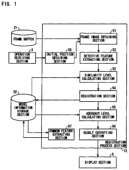
FIG. 1 is a block diagram depicting an exemplary computing environment that is suitable for use with certain implementations of the present invention.
FIG. 2 is a block diagram depicting an exemplary representative device that is suitable for use with certain implementations of the present invention.
FIG. 3 is an illustrative diagram depicting Direct Prediction in B picture coding, in accordance with certain exemplary implementations of the present invention.
FIG. 4 is an illustrative diagram depicting handling of collocated Intra within existing codecs wherein motion is assumed to be zero, in accordance with certain exemplary implementations of the present invention.
FIG. 5 is an illustrative diagram demonstrating that Direct Mode parameters need to be determined when the reference picture index of the collocated block in the backward reference P picture is other than zero, in accordance with certain exemplary implementations of the present invention.
FIG. 6 is an illustrative diagram showing a scene change and/or the situation wherein the collocated block is intra-coded, in accordance with certain exemplary implementations of the present invention.
FIG. 7 is an illustrative diagram depicting a scheme wherein MV.sub.FW and MV.sub.BW are derived from spatial prediction (e.g., Median MV of surrounding Macroblocks) and wherein if either one is not available (e.g., no predictors) then one-direction may be used, in accordance with certain exemplary implementations of the present invention.
FIG. 8 is an illustrative diagram depicting how spatial prediction may be employed to solve the problem of scene changes and/or that Direct Mode need not be restricted to being Bidirectional, in accordance with certain exemplary implementations of the present invention.
FIG. 9 is an illustrative diagram depicting Timestamp Independent SpatioTemporal Prediction for Direct Mode, in accordance with certain exemplary implementations of the present invention.
FIGS. 10a-b are illustrative diagrams showing how Direct/Skip Mode decision can be performed either by an adaptive picture level RDO decision and/or by user scheme selection, in accordance with certain exemplary implementations of the present invention.
FIG. 11 is a table listing some syntax changes that can be used in header information, in accordance with certain exemplary implementations of the present invention.
FIG. 12 is an illustrative diagram depicting different frames which signal the use of a different type of prediction for their corresponding Direct (B) and Skip (P) modes. P.sub.Z, P.sub.T, and P.sub.M, define for example zero, temporal and spatial prediction, and B.sub.T, B.sub.SP, define temporal and spatial prediction for Direct Mode, in accordance with certain exemplary implementations of the present invention.
FIG. 13 is a table showing modifications to modes for 8.times.8 blocks in B pictures/slices applicable to the H.264/AVC coding scheme, in accordance with certain exemplary implementations of the present invention.
FIG. 14 is an illustrative diagram depicting median prediction of motion vectors, in accordance with certain exemplary implementations of the present invention.
FIG. 15 is a table showing P-Picture Motion Vector prediction (e.g., Non-Skip, non-8.times.16, non-16.times.8 MBs), in accordance with certain exemplary implementations of the present invention.
FIG. 16 is an illustrative diagram depicting median prediction of motion vectors, in accordance with certain exemplary implementations of the present invention.
FIG. 17 is an illustrative diagram showing replacement of Intra subblock predictors with adjacent Inter subblock predictors, in accordance with certain exemplary implementations of the present invention.
FIG. 18 is an illustrative diagram depicting how Motion Vector Prediction of current block (C) may consider the reference frame information of the predictor macroblocks (Pr) and perform the proper adjustments (e.g., scaling of the predictors), in accordance with certain exemplary implementations of the present invention.
FIG. 19 is an illustrative diagram depicting certain exemplary predictors for 8.times.8 partitioning, in accordance with certain exemplary implementations of the present invention.
FIG. 20 is a table showing the relationship between previous .lamda. and current .lamda., in accordance with certain exemplary implementations of the present invention.
FIG. 21 is a table showing the performance difference of exemplary proposed schemes and proposed RDO versus conventional software (i.e., H.264/AVC JM3.3), in accordance with certain exemplary implementations of the present invention.
FIG. 22 is a table showing a comparison of encoding performance for different values of .lamda., in accordance with certain exemplary implementations of the present invention.
FIG. 23 is an illustrative timeline showing a situation wherein reference pictures of a macroblock partition temporally precede a current picture, in accordance with certain exemplary implementations of the present invention.
Detailed description
While various methods and apparatuses are described and illustrated herein, it should be kept in mind that the techniques of the present invention are not limited to the examples described and shown in the accompanying drawings, but are also clearly adaptable to other similar existing and future video coding schemes, etc.
Before introducing such exemplary methods and apparatuses, an introduction is provided in the following section for suitable exemplary operating environments, for example, in the form of a computing device and other types of devices/appliances.
Exemplary Operational Environments:
Turning to the drawings, wherein like reference numerals refer to like elements, the invention is illustrated as being implemented in a suitable computing environment. Although not required, the invention will be described in the general context of computer-executable instructions, such as program modules, being executed by a personal computer.
Generally, program modules include routines, programs, objects, components, data structures, etc. that perform particular tasks or implement particular abstract data types. Those skilled in the art will appreciate that the invention may be practiced with other computer system configurations, including hand-held devices, multi-processor systems, microprocessor based or programmable consumer electronics, network PCs, minicomputers, mainframe computers, portable communication devices, and the like.
The invention may also be practiced in distributed computing environments where tasks are performed by remote processing devices that are linked through a communications network. In a distributed computing environment, program modules may be located in both local and remote memory storage devices.
FIG. 1 illustrates an example of a suitable computing environment 120 on which the subsequently described systems, apparatuses and methods may be implemented. Exemplary computing environment 120 is only one example of a suitable computing environment and is not intended to suggest any limitation as to the scope of use or functionality of the improved methods and systems described herein. Neither should computing environment 120 be interpreted as having any dependency or requirement relating to any one or combination of components illustrated in computing environment 120.
The improved methods and systems herein are operational with numerous other general purpose or special purpose computing system environments or configurations. Examples of well known computing systems, environments, and/or configurations that may be suitable include, but are not limited to, personal computers, server computers, thin clients, thick clients, hand-held or laptop devices, multiprocessor systems, microprocessor-based systems, set top boxes, programmable consumer electronics, network PCs, minicomputers, mainframe computers, distributed computing environments that include any of the above systems or devices, and the like.
As shown in FIG. 1, computing environment 120 includes a general-purpose computing device in the form of a computer 130. The components of computer 130 may include one or more processors or processing units 132, a system memory 134, and a bus 136 that couples various system components including system memory 134 to processor 132.
Bus 136 represents one or more of any of several types of bus structures, including a memory bus or memory controller, a peripheral bus, an accelerated graphics port, and a processor or local bus using any of a variety of bus architectures. By way of example, and not limitation, such architectures include Industry Standard Architecture (ISA) bus, Micro Channel Architecture (MCA) bus, Enhanced ISA (EISA) bus, Video Electronics Standards Association (VESA) local bus, and Peripheral Component Interconnects (PCI) bus also known as Mezzanine bus.
Computer 130 typically includes a variety of computer readable media. Such media may be any available media that is accessible by computer 130, and it includes both volatile and non-volatile media, removable and non-removable media.
In FIG. 1, system memory 134 includes computer readable media in the form of volatile memory, such as random access memory (RAM) 140, and/or non-volatile memory, such as read only memory (ROM) 138. A basic input/output system (BIOS) 142, containing the basic routines that help to transfer information between elements within computer 130, such as during start-up, is stored in ROM 138. RAM 140 typically contains data and/or program modules that are immediately accessible to and/or presently being operated on by processor 132.
Computer 130 may further include other removable/non-removable, volatile/non-volatile computer storage media. For example, FIG. 1 illustrates a hard disk drive 144 for reading from and writing to a non-removable, non-volatile magnetic media (not shown and typically called a "hard drive"), a magnetic disk drive 146 for reading from and writing to a removable, non-volatile magnetic disk 148 (e.g., a "floppy disk"), and an optical disk drive 150 for reading from or writing to a removable, non-volatile optical disk 152 such as a CD-ROM/R/RW, DVD-ROM/R/RW/+R/RAM or other optical media. Hard disk drive 144, magnetic disk drive 146 and optical disk drive 150 are each connected to bus 136 by one or more interfaces 154.
The drives and associated computer-readable media provide nonvolatile storage of computer readable instructions, data structures, program modules, and other data for computer 130. Although the exemplary environment described herein employs a hard disk, a removable magnetic disk 148 and a removable optical disk 152, it should be appreciated by those skilled in the art that other types of computer readable media which can store data that is accessible by a computer, such as magnetic cassettes, flash memory cards, digital video disks, random access memories (RAMs), read only memories (ROM), and the like, may also be used in the exemplary operating environment.
A number of program modules may be stored on the hard disk, magnetic disk 148, optical disk 152, ROM 138, or RAM 140, including, e.g., an operating system 158, one or more application programs 160, other program modules 162, and program data 164.
The improved methods and systems described herein may be implemented within operating system 158, one or more application programs 160, other program modules 162, and/or program data 164.
A user may provide commands and information into computer 130 through input devices such as keyboard 166 and pointing device 168 (such as a "mouse"). Other input devices (not shown) may include a microphone, joystick, game pad, satellite dish, serial port, scanner, camera, etc. These and other input devices are connected to the processing unit 132 through a user input interface 170 that is coupled to bus 136, but may be connected by other interface and bus structures, such as a parallel port, game port, or a universal serial bus (USB).
A monitor 172 or other type of display device is also connected to bus 136 via an interface, such as a video adapter 174. In addition to monitor 172, personal computers typically include other peripheral output devices (not shown), such as speakers and printers, which may be connected through output peripheral interface 175.
Computer 130 may operate in a networked environment using logical connections to one or more remote computers, such as a remote computer 182. Remote computer 182 may include many or all of the elements and features described herein relative to computer 130.
Logical connections shown in FIG. 1 are a local area network (LAN) 177 and a general wide area network (WAN) 179. Such networking environments are commonplace in offices, enterprise-wide computer networks, intranets, and the Internet.
When used in a LAN networking environment, computer 130 is connected to LAN 177 via network interface or adapter 186. When used in a WAN networking environment, the computer typically includes a modem 178 or other means for establishing communications over WAN 179. Modem 178, which may be internal or external, may be connected to system bus 136 via the user input interface 170 or other appropriate mechanism.
Depicted in FIG. 1, is a specific implementation of a WAN via the Internet. Here, computer 130 employs modem 178 to establish communications with at least one remote computer 182 via the Internet 180.
In a networked environment, program modules depicted relative to computer 130, or portions thereof, may be stored in a remote memory storage device. Thus, e.g., as depicted in FIG. 1, remote application programs 189 may reside on a memory device of remote computer 182. It will be appreciated that the network connections shown and described are exemplary and other means of establishing a communications link between the computers may be used.
Attention is now drawn to FIG. 2, which is a block diagram depicting another exemplary device 200 that is also capable of benefiting from the methods and apparatuses disclosed herein. Device 200 is representative of any one or more devices or appliances that are operatively configured to process video and/or any related types of data in accordance with all or part of the methods and apparatuses described herein and their equivalents. Thus, device 200 may take the form of a computing device as in FIG. 1, or some other form, such as, for example, a wireless device, a portable communication device, a personal digital assistant, a video player, a television, a DVD player, a CD player, a karaoke machine, a kiosk, a digital video projector, a flat panel video display mechanism, a set-top box, a video game machine, etc. In this example, device 200 includes logic 202 configured to process video data, a video data source 204 configured to provide video data to logic 202, and at least one display module 206 capable of displaying at least a portion of the video data for a user to view. Logic 202 is representative of hardware, firmware, software and/or any combination thereof. In certain implementations, for example, logic 202 includes a compressor/decompressor (codec), or the like. Video data source 204 is representative of any mechanism that can provide, communicate, output, and/or at least momentarily store video data suitable for processing by logic 202. Video reproduction source is illustratively shown as being within and/or without device 200. Display module 206 is representative of any mechanism that a user might view directly or indirectly and see the visual results of video data presented thereon. Additionally, in certain implementations, device 200 may also include some form or capability for reproducing or otherwise handling audio data associated with the video data. Thus, an audio reproduction module 208 is shown.
With the examples of FIG. 1 and FIG. 2 in mind, and others like them, the next sections focus on certain exemplary methods and apparatuses that may be at least partially practiced using with such environments and with such devices.
Conventional Direct Mode coding typically considerably improves coding efficiency of B frames by exploiting the statistical dependence that may exist between video frames. For example, Direct Mode can effectively represent block motion without having to transmit motion information. The statistical dependence that has been exploited thus far has been temporal dependence, which unfortunately implies that the timestamp information for each frame has to be available in both the encoder and decoder logic. Furthermore, the performance of this mode tends to deteriorate as the distance between frames increases since temporal statistical dependence also decreases. Such problems become even greater when multiple frame referencing is enabled, for example, as is the case of the H.264/AVC codec.
In this description improved methods and apparatuses are presented for calculating direct mode parameters that can achieve significantly improved coding efficiency when compared to current techniques. The improved methods and apparatuses also address the timestamp independency issue, for example, as described above. The improved methods and apparatuses herein build upon concepts that have been successfully adopted in P frames, such as, for example, for the encoding of a skip mode and exploiting the Motion Vector Predictor used for the encoding of motion parameters within the calculation of the motion information of the direct mode. An adaptive technique that efficiently combines temporal and spatial calculations of the motion parameters has been separately proposed.
In accordance with certain aspects of the present invention, the improved methods and apparatuses represent modifications, except for the case of the adaptive method, that do not require a change in the draft H.264/AVC bitstream syntax as it existed prior to July of 2002, for example. As such, in certain implementations the encoder and decoder region prediction logic may be the only aspects in such a standards-based system that need to be altered to support the improvements in compression performance that are described herein.
In terms of the use of these principles in a coding scheme such as the draft H.264/AVC standard, for example, other possible exemplary advantages provided by the improved methods and apparatuses include: timestamp independent calculation of direct parameters; likely no syntax changes; no extensive increase in complexity in the encoder logic and/or decoder logic; likely no requirement for (time-consuming/processor intensive) division in the calculations; considerable reduction of memory needed for storing motion parameters; relatively few software changes (e.g., when the motion vector prediction for 16.times.16 mode is reused); the overall compression-capability performance should be very close or considerably better than the direct mode in the H.264/AVC standard (software) as it existed prior to July of 2002; and enhanced robustness to unconventional temporal relationships with reference pictures since temporal relationship assumptions (e.g., such as assumptions that one reference picture for the coding of a B picture is temporally preceding the B picture and that the other reference picture for the coding of a B picture is temporally following the B picture) can be avoided in the MV prediction process.
In accordance with certain other aspects of the present invention, improvements on the current Rate Distortion Optimization (RDO) for B frames are also described herein, for example, by conditionally considering the Non-Residual Direct Mode during the encoding process, and/or by also modifying the Lagrangian .lamda. parameter of the RDO. Such aspects of the present invention can be selectively combined with the improved techniques for Direct Mode to provide considerable improvements versus the existing techniques/systems.
Attention is drawn now to FIG. 3, which is an illustrative diagram depicting Direct Prediction in B frame coding, in accordance with certain exemplary implementations of the present invention.
The introduction of the Direct Prediction mode for a Macroblock/block within B frames, for example, is one of the main reasons why B frames can achieve higher coding efficiency, in most cases, compared to P frames. According to this mode as in the draft H.264/AVC standard, no motion information is required to be transmitted for a Direct Coded Macroblock/block, since it can be directly derived from previously transmitted information. This eliminates the high overhead that motion information can require. Furthermore, the direct mode exploits bidirectional prediction which allows for further increase in coding efficiency. In the example shown in FIG. 3, a B frame picture is coded with use of two reference pictures, a backward reference picture that is a P frame at a time t+2 that is temporally subsequent to the time t+1 of the B frame and a forward reference picture that is a P frame at a time t that is temporally previous to the B frame. It shall be appreciated by those familiar with the art that the situation shown in FIG. 3 is only an example, and in particular that the terms "forward" and "backward" may be used to apply to reference pictures that have any temporal relationship with the picture being coded (i.e., that a "backward" or "forward" reference picture may be temporally prior to or temporally subsequent to the picture being coded).
Motion information for the Direct Mode as in the draft H.264/AVC standard as it existed prior to July 2002 is derived by considering and temporally scaling the motion parameters of the collocated macroblock/block of the backward reference picture as illustrated in FIG. 3. Here, an assumption is made that an object captured in the video picture is moving with constant speed. This assumption makes it possible to predict a current position inside a B picture without having to transmit any motion vectors. By way of example, the motion vectors ({right arrow over (MV)}.sub.fw,{right arrow over (MV)}.sub.bw) of the Direct Mode versus the motion vector {right arrow over (MV)} the collocated block in the first backward reference frame can be calculated by:
.times..times..times..times..times..times. ##EQU00001##
where TR.sub.B is the temporal distance between the current B frame and the reference frame pointed by the forward MV of the collocated MB, and TR.sub.D is the temporal distance between the backward reference frame and the reference frame pointed by the forward MV of the collocated region in the backward reference frame. The same reference frame that was used by the collocated block was also used by the Direct Mode block. Until recently, for example, this was also the method followed within the work on the draft H.264/AVC standard, and still existed within the latest H.264/AVC reference software prior to July of 2002 (see, e.g., H.264/AVC Reference Software, unofficial software release Version 3.7).
As demonstrated by the example in FIG. 3 and the scaling equation
above, the draft H.264/AVC standard as it existed prior to July of 2002 and other like coding methods present certain drawbacks since they usually require that both the encoder and decoder have a priori knowledge of the timestamp information for each picture. In general, and especially due to the design of H.264/AVC which allows reference pictures almost anywhere in time, timestamps cannot be assumed by the order that a picture arrives at the decoder. Current designs typically do not include precise enough timing information in the syntax to solve this problem. A relatively new scheme was also under investigation for work on H.264/AVC, however, which in a sense does not require the knowledge of time. Here, the new H.264/AVC scheme includes three new parameters, namely, direct_mv_scale_fwd, direct_mv_scale_bwd, and direct_mv_divisor to the picture header and according to which the motion vectors of the direct mode can be calculated as follows:
.times..times..times..times..times..times..times..times..times..times. ##EQU00002##
Reference is now made to FIG. 4, which is an illustrative diagram depicting handling of collocated Intra within existing codecs wherein motion is assumed to be zero, in accordance with certain exemplary implementations of the present invention.
Reference is made next to FIG. 5, which is an illustrative diagram demonstrating that Direct Mode parameters need to be determined when the reference frame used to code the collocated block in the backward reference P picture is not the most recent reference picture that precedes the B picture to be coded (e.g., when the reference index is not equal to zero if the value zero for a reference index indicates the most recent temporally-previous forward reference picture). The new H.264/AVC scheme described above unfortunately has itself several drawbacks. For example, the H.264/AVC standard allows for multiple frame referencing and long-term storage of pictures as illustrated in FIG. 5. The new H.264/AVC scheme above fails to consider that different reference frames require different scaling factors. As such, for example, a significant reduction in coding efficiency has been reported (e.g., up to 10% loss in B frame coding efficiency). It is also quite uncertain what exactly the temporal relationship might be between the current block and its collocated block in such a case since the constant motion assumption described above is no longer followed. Additionally, temporal statistical relationships are reduced even further as reference frames become more temporally distant compared to one another.
Other issues include the inefficiency of the above new H.264/AVC scheme to handle intra blocks as shown in FIG. 4, for example, and/or even intra pictures. such as, for example, in the case of a scene change as shown in FIG. 6, which is an illustrative diagram showing a scene change and/or the situation wherein the collocated block is intra-coded. Currently, for example, a typically codec would assume that motion information is zero and use the first backward and forward reference pictures to perform bidirectional motion compensation. In this example, it may be more likely that the two collocated blocks from the forward and backward references have little, if any, relationship. Therefore, the usage of intra coding in the backward reference picture (shown as picture I in FIG. 6) in this case would likely cause a significantly reduction in the coding efficiency for the coding of the B pictures neighboring the scene change.
In the case of a scene change, for example, as in FIG. 6, where there is obviously no relationship between the two reference frames, a bidirectional prediction would usually provide no benefit. This implies that the Direct Mode, as previously defined, could be completely wasted. Unfortunately, current implementations of the Direct Mode usually are defined to always perform bidirectional prediction of a Macroblock/block.
Even if temporal distance parameters were available, it is not certain that the usage of the Direct Mode as conventionally defined is the most appropriate solution. In particular, for B frames that are temporally closer to a first temporally-previous forward reference frame, the statistical dependence might be much stronger with that frame than it would be for a temporally-subsequent backward reference frame. One example is a sequence where scene A changes to scene B, and then moves back to scene A (e.g., as might be the case in a news bulletin). The resulting performance of B frame encoding would likely suffer since Direct Mode will not be effectively exploited within the encoding process.
Unlike the conventional definitions of the Direct Mode where only temporal prediction was used, in co-pending patent application Ser. No. 10/444,511, which is incorporated herein by reference, several alternative improved methods and apparatuses are described for the assignment of the Direct Mode motion parameters wherein both temporal and/or spatial prediction are considered.
With these schemes and concepts in mind, in accordance with certain aspects of the present invention, presented below are some exemplary adaptive methods and apparatuses that combine such schemes and/or improve upon them to achieve even better coding performance under various conditions.
By way of example, in certain methods and apparatuses described below a high degree of statistical dependence of the motion parameters of adjacent macroblocks is exploited in order to further improve the efficiency of the SKIP Macroblock Mode for P pictures. For example, efficiency can be increased by allowing the SKIP mode to also use motion parameters, taken as the Motion Vector Predictor parameters of a current (16.times.16) Inter Mode. The same technique may also apply for B frames, wherein one may also generate both backward and forward motion vectors for the Direct mode using the Motion Vector Predictor of the backward or forward (16.times.16) Inter modes, respectively. It is also noted, for example, that one may even refine this prediction to other levels (e.g., 8.times.8, 4.times.4, etc.), however doing so would typically complicate the design.
In accordance with certain exemplary implementations of the present invention methods and apparatuses are provided to correct at least some of the issues presented above, such as, for example, the case of the collocated region in the backward reference picture using a different reference frame than the current picture will use and/or being intra coded. In accordance with certain other exemplary implementations of the present invention methods and apparatuses are provided which use a spatial-prediction based Motion Vector Predictor (MVP) concept to provide other benefits to the direct mode, such as, for example, the removal of division processing and/or memory reduction.
Direct Mode with INTRA and Non-Zero Reference Correction:
FIG. 7 is an illustrative diagram depicting a scheme wherein MV.sub.FW and MV.sub.BW are derived from spatial prediction (e.g., Median MV of forward and/or backward motion vector values of surrounding Macroblocks that use the same reference index) and wherein if either one is not available (e.g., no predictors) then one-direction prediction (e.g., forward-only prediction or backward-only prediction) may be used, in accordance with certain exemplary implementations of the present invention.
In accordance with certain exemplary methods, if a collocated block in the backward reference picture uses a zero-reference frame index and if also its reference picture exists in the reference buffer for the decoding process of the current picture to be decoded, then a scheme, such as, demonstrated above using equation
or the like is followed. Otherwise, a spatial-prediction based Motion Vector Predictor (MVP) for both directions (forward and backward) is used instead. By way of example, in the case of a collocated block being intra-coded or having a different reference frame index than the reference frame index to be used for the block of the current picture, or even the reference frame not being available anymore, then spatial-prediction MVP is used.
The spatial-prediction MVP can be taken, for example, as the motion vector predicted for the encoding of the current (16.times.16) Inter Mode (e.g., essentially with the usage of MEDIAN prediction or the like). This method in certain implementations is further modified by using different sized block or portions. For example, the method can be refined by using smaller block sizes. However, this tends to complicate the design sometimes without as much compression gain improvement. For the case of a Direct sub-partition within a P8.times.8 structure, for example, this method may still use a 16.times.16 MVD, even though this could be corrected to consider surrounding blocks.
Unlike the case of Skip Mode in a P picture, in accordance with certain aspects of the present invention, the motion vector predictor is not restricted to use exclusively the zero reference frame index. Here, for example, an additional Reference Frame Prediction process may be introduced for selecting the reference frame that is to be used for either the forward or backward reference. Those skilled in the art will recognize that this type of prediction may also be applied in P frames as well.
If no reference exists for prediction (e.g., the surrounding Macroblocks are using forward prediction and thus there exists no backward reference), then the direct mode can be designed such that it becomes a single direction prediction mode. This consideration can potentially solve several issues such as inefficiency of the H.264/AVC scheme prior to July of 2002 in scene changes, when new objects appear within a scene, etc. This method also solves the problem of both forward and backward reference indexes pointing to temporally-future reference pictures or both pointing to temporally-subsequent reference pictures, and/or even when these two reference pictures are the same picture altogether.
The description continues in the full USPTO document.
 Lapsed, fee not paid6 drawings