Background
1.
Field
The present invention relates generally to communications, and more specifically to a wireless LAN protocol stack.
2.
Background
Wireless communication systems are widely deployed to provide various types of communication such as voice and data. A typical wireless data system, or network, provides multiple users access to one or more shared resources. A system may use a variety of multiple access techniques such as Frequency Division Multiplexing (FDM), Time Division Multiplexing (TDM), Code Division Multiplexing (CDM), and others.
Example wireless networks include cellular-based data systems. The following are several such examples:
the "TIA/EIA-95-B Mobile Station-Base Station Compatibility Standard for Dual-Mode Wideband Spread Spectrum Cellular System" (the IS-95 standard),
the standard offered by a consortium named "3rd Generation Partnership Project" (3GPP) and embodied in a set of documents including Document Nos. 3G TS 25.211, 3G TS 25.212, 3G TS 25.213, and 3G TS 25.214 (the W-CDMA standard),
the standard offered by a consortium named "3rd Generation Partnership Project 2" (3GPP2) and embodied in "TR-45.5 Physical Layer Standard for cdma2000 Spread Spectrum Systems" (the IS-2000 standard), and
the high data rate (HDR) system that conforms to the TIA/EIA/IS-856 standard (the IS-856 standard).
Other examples of wireless systems include Wireless Local Area Networks (WLANs) such as the IEEE 802.11 standards (i.e. 802.11(a), (b), or (g)). Improvements over these networks may be achieved in deploying a Multiple Input Multiple Output (MIMO) WLAN comprising Orthogonal Frequency Division Multiplexing (OFDM) modulation techniques.
As wireless system designs have advanced, higher data rates have become available. Higher data rates have opened up the possibility of advanced applications, among which are voice, video, fast data transfer, and various other applications. However, various applications may have differing requirements for their respective data transfer. Many types of data may have latency and throughput requirements, or need some Quality of Service (QoS) guarantee. Without resource management, the capacity of a system may be reduced, and the system may not operate efficiently.
Medium Access Control (MAC) protocols are commonly used to allocate a shared communication resource between a number of users. MAC protocols commonly interface higher layers to the physical layer used to transmit and receive data. To benefit from an increase in data rates, a MAC protocol must be designed to utilize the shared resource efficiently.
The high performance systems being developed support multiple rates, which may vary widely based on physical link characteristics. Given the varying demands of different data application types, and the large variance of supportable data rates to different user terminals located within a system, advances in how to queue the various traffic types and how to transmit them on the often disparate various physical links need to be developed as well. There is therefore a need in the art for MAC processing for efficient use of high throughput systems.
Summary
Embodiments disclosed herein address the need in the art for MAC processing for efficient use of high throughput systems. In one aspect, a protocol stack is disclosed comprising one or more of the following: an adaptation layer, a data link control layer, a physical layer, and a layer manager. A MAC sublayer Protocol Data Unit adaptable for including data from multiple flows is disclosed. Various features and aspects are detailed further below.
In another aspect, physical layer feedback is used for adaptation layer processing. In one embodiment, physical layer feedback is used for segmentation. In another embodiment, physical layer feedback is used for multicast mapping onto one or more unicast channels. In yet another embodiment, a combination of unicast, multicast, or broadcast channels may be selected to perform multicast transmission in response to physical layer feedback corresponding to the various channels.
In another aspect, a data unit for transmission from a first station to a second station comprises zero or more complete sub-data units, zero or one partial sub-data units from a prior transmission, and zero or one partial sub-data units to fill the data unit. In one embodiment, a pointer may be used to indicate the location of any complete sub-data units. A partial sub-data unit may be inserted at a pre-determined location. Partial sub-data units may be combined with previously stored partial sub-data units, or may be stored for later use. In one embodiment, a sub-data unit may be a MUX sublayer Protocol Data Unit (MUX PDU).
Various other aspects and embodiments are also presented. These aspects have the benefit of providing efficient media access control, and are advantageously used with physical layers comprising high data rates, as well as low data rates.
Brief description of the drawings
FIG. 1 is an example embodiment of a system including a high-speed WLAN;
FIG. 2 depicts an example embodiment of a wireless communication device, which may be configured as an access point or user terminal;
FIG. 3 depicts an example Sub-network Protocol Stack;
FIG. 4 illustrates a user data packet as it traverses through the layers of the protocol stack;
FIG. 5 illustrates an example MAC frame;
FIG. 6 depicts an example method for transmitting a forward link message transfer;
FIG. 7 depicts an example method for receiving a forward link message transfer;
FIG. 8 depicts an example method for transmitting a reverse link message transfer;
FIG. 9 depicts an example method for receiving a reverse link message transfer;
FIG. 10 depicts an example method for performing initial access and registration at a UT;
FIG. 11 depicts an example method for performing initial access and registration at the AP;
FIG. 12 depicts an example method 1200 for user data flow at the AP;
FIG. 13 depicts an example method 1300 for user data flow at the UT;
FIG. 14 depicts an example method for incorporating physical layer feedback into adaptation layer functions;
FIG. 15 depicts an example method for performing adaptation layer multicast;
FIG. 16 illustrates an example method for determining whether to use adaptation layer multicast or MAC layer multicast;
FIG. 17 depicts an example method for performing segmentation in response to physical layer feedback;
FIG. 18 illustrates segmenting in response to a transmission rate;
FIG. 19 depicts an example method for transmitting multiple flows and commands in a single MAC frame;
FIG. 20 illustrates sequential MAC frames, including examples of transmitting various partial MUX PDUs;
FIG. 21 illustrates an example method for preparing a MAC frame using a MUX pointer;
FIG. 22 illustrates an example method for receiving a MAC frame comprising a MUX pointer;
FIG. 23 illustrates example MUX PDU formats.
FIG. 24 illustrates an example system configured for Ethernet adaptation;
FIG. 25 illustrates an example system configured for IP adaptation;
FIG. 26 illustrates example Ethernet protocol stacks; and
FIG. 27 illustrates example IP protocol stacks.
Detailed description
A sub-network protocol stack is disclosed herein that supports highly efficient, low latency, high throughput operation in conjunction with very high bit rate physical layers for the wireless LAN (or similar applications that use newly emerging transmission technologies). The example WLAN supports bit rates in excess of 100 Mbps (million bits per second) in bandwidths of 20 MHz.
Described along with the protocol stack is a method for multiplexing Protocol Data Units (PDUs) from multiple user data streams and sub-network control entities (MUX PDUs) into a single byte stream. The byte stream is formatted into MAC protocol data units (MAC PDUs), each of which may be transmitted in a burst that is contained within a single MAC frame. This may support a high performance wireless LAN sub-network for highly efficient, low latency, high throughput operation in conjunction with very high bit rate physical layers.
The sub-network protocol stack supports high data rate, high bandwidth physical layer transport mechanisms in general, including, but not limited to, those based on OFDM modulation, single carrier modulation techniques, systems using multiple transmit and multiple receive antennas (Multiple Input Multiple Output (MIMO) systems, including Multiple Input Single Output (MISO) systems) for very high bandwidth efficiency operation, systems using multiple transmit and receive antennas in conjunction with spatial multiplexing techniques to transmit data to or from multiple user terminals during the same time interval, and systems using code division multiple access (CDMA) techniques to allow transmissions for multiple users simultaneously.
One or more exemplary embodiments described herein are set forth in the context of a wireless data communication system. While use within this context is advantageous, different embodiments of the invention may be incorporated in different environments or configurations. In general, the various systems described herein may be formed using software-controlled processors, integrated circuits, or discrete logic. The data, instructions, commands, information, signals, symbols, and chips that may be referenced throughout the application are advantageously represented by voltages, currents, electromagnetic waves, magnetic fields or particles, optical fields or particles, or a combination thereof. In addition, the blocks shown in each block diagram may represent hardware or method steps. Method steps can be interchanged without departing from the scope of the present invention. The word "exemplary" is used herein to mean "serving as an example, instance, or illustration." Any embodiment described herein as "exemplary" is not necessarily to be construed as preferred or advantageous over other embodiments.
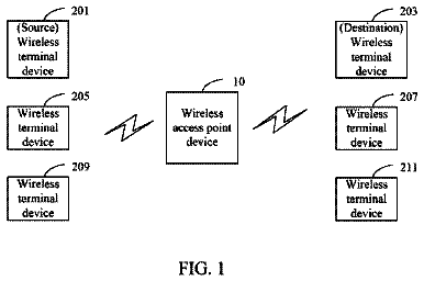
FIG. 1 is an example embodiment of system 100, comprising an Access Point (AP) 104 connected to one or more User Terminals (UTs) 106A-N. The AP and the UTs communicate via Wireless Local Area Network (WLAN) 120. In the example embodiment, WLAN 120 is a high speed MIMO OFDM system. However, WLAN 120 may be any wireless LAN. Access point 104 communicates with any number of external devices or processes via network 102. Network 102 may be the Internet, an intranet, or any other wired, wireless, or optical network. Connection 110 carries the physical layer signals from the network to the access point 104. Devices or processes may be connected to network 102 or as UTs (or via connections therewith) on WLAN 120. Examples of devices that may be connected to either network 102 or WLAN 120 include phones, Personal Digital Assistants (PDAs), computers of various types (laptops, personal computers, workstations, terminals of any type), video devices such as cameras, camcorders, webcams, and virtually any other type of data device. Processes may include voice, video, data communications, etc. Various data streams may have varying transmission requirements, which may be accommodated by using varying Quality of Service (QoS) techniques.
System 100 is deployed with a centralized AP 104. All UTs 106 communicate with the AP in the example embodiment. In an alternate embodiment, direct peer-to-peer communication between two UTs may be accommodated, with modifications to the system, as will be apparent to those of skill in the art. For clarity of discussion, in the example embodiment, access to the physical layer transport mechanism is controlled by the AP.
In one embodiment, AP 104 provides Ethernet adaptation, an example of which is illustrated in FIG. 24 In this case, an IP router 2410 may be deployed with the AP 104 to provide connection (via Ethernet connection 110) to network 102. Illustrative example UTs 106 are shown, for example, cell phone 106A, Personal Digital Assistant (PDA) 106B, laptop 106C, workstation 106D, personal computer 106E, video camcorder 106F, and video projector 106G. Ethernet frames may be transferred between the router and the UTs 106 over the WLAN sub-network 120 (detailed below).
Ethernet adaptation and connectivity are well known in the art. FIG. 26 illustrates Ethernet adaptation protocol stacks 2640 and 2650 for an example UT 106 and AP 104, respectively, as integrated with example layers detailed further below. UT protocol stack 2640 comprises upper layers 2610, IP layer 2615, Ethernet MAC layer 2620A, adaptation layer 310A, data link layer 320A, and physical layer (PHY) 240A. AP protocol stack 2650 comprises PHY 240B (connected to UT PHY 240A via RF link 120), data link layer 320B, and adaptation layer 310B. Ethernet MAC 2620B connects adaptation layer 310B to Ethernet PHY 2625, which is connected 110 with wired network 102.
In an alternate embodiment, AP 104 provides IP Adaptation, an example of which is illustrated in FIG. 25. In this case, the AP 104 acts as a gateway router for the set of connected UTs (as described with respect to FIG. 24). In this case, IP datagrams may be routed by the AP 104 to and from the UTs 106.
IP adaptation and connectivity are well known in the art. FIG. 27 illustrates IP adaptation protocol stacks 2740 and 2750 for an example UT 106 and AP 104, respectively, as integrated with example layers detailed further below. UT protocol stack 2740 comprises upper layers 2710, IP layer 2720A, adaptation layer 310A, data link layer 320A, and physical layer (PHY) 240A. AP protocol stack 2750 comprises PHY 240B (connected to UT PHY 240A via RF link 120), data link layer 320B, and adaptation layer 310B. IP layer 2720B connects adaptation layer 310B to Ethernet MAC 2725 which is connected to Ethernet PHY 2730. Ethernet PHY 2730 is connected 110 with wired network 102.
FIG. 2 depicts an example embodiment of a wireless communication device, which may be configured as an access point 104 or user terminal 106. An access point 104 configuration is shown in FIG. 2. Transceiver 210 receives and transmits on connection 110 according to the physical layer requirements of network 102. Data from or to devices or applications connected to network 102 are delivered to MAC processor 220. These data are referred to herein as flows 260. Flows may have different characteristics and may require different processing based on the type of application associated with the flow. For example, video or voice may be characterized as low-latency flows (video generally having higher throughput requirements than voice). Many data applications are less sensitive to latency, but may have higher data integrity requirements (i.e., voice may be tolerant of some packet loss, file transfer is generally intolerant of packet loss).
MAC processor 220 receives flows 260 and processes them for transmission on the physical layer. MAC processor 220 also receives physical layer data and processes the data to form packets for outgoing flows 260. Internal control and signaling is also communicated between the AP and the UTs. MAC Protocol Data Units (MAC PDUs) are delivered to and received from wireless LAN transceiver 240 on connection 270. Conversion from flows and commands to MAC PDUs, and vice versa, is detailed below. Feedback 280 corresponding to the various MAC IDs is returned from the physical layer (PHY) 240 to MAC processor 220 for various purposes, detailed further below. Feedback 280 may comprise any physical layer information, including supportable rates for channels (including multicast as well as unicast channels), modulation format, and various other parameters.
In an example embodiment, the Adaptation layer (ADAP) and Data Link Control layer (DLC) are performed in MAC processor 220. The physical layer (PHY) is performed on wireless LAN transceiver 240. Those of skill in the art will recognize that the segmentation of the various functions may be made in any of a variety of configurations. MAC processor 220 may perform some or all of the processing for the physical layer. A wireless LAN transceiver may include a processor for performing MAC processing, or subparts thereof. Any number of processors, special purpose hardware, or combination thereof may be deployed.
MAC processor 220 may be a general-purpose microprocessor, a digital signal processor (DSP), or a special-purpose processor. MAC processor 220 may be connected with special-purpose hardware to assist in various tasks (details not shown). Various applications may be run on externally connected processors, such as an externally connected computer or over a network connection, may run on an additional processor within access point 104 (not shown), or may run on MAC processor 220 itself. MAC processor 220 is shown connected with memory 255, which may be used for storing data as well as instructions for performing the various procedures and methods described herein. Those of skill in the art will recognize that memory 255 may be comprised of one or more memory components of various types, that may be embedded in whole or in part within MAC processor 220.
In addition to storing instructions and data for performing functions described herein, memory 255 may also be used for storing data associated with various queues (detailed further below). Memory 255 may include UT proxy queues (described below).
Wireless LAN transceiver 240 may be any type of transceiver. In an example embodiment, wireless LAN transceiver 240 is an OFDM transceiver, which may be operated with a MIMO or MISO interface. OFDM, MIMO, and MISO are known to those of skill in the art. Various example OFDM, MIMO and MISO transceivers are detailed in co-pending U.S. patent application Ser. No. 10/650,295, entitled "FREQUENCY-INDEPENDENT SPATIAL-PROCESSING FOR WIDEBAND MISO AND MIMO SYSTEMS," filed Aug. 27, 2003, assigned to the assignee of the present invention.
Wireless LAN transceiver 240 is shown connected with antennas 250 A-N. Any number of antennas may be supported in various embodiments. Antennas 250 are used to transmit and receive on WLAN 120.
Wireless LAN transceiver 240 may comprise a spatial processor connected to each of the one or more antennas 250. The spatial processor may process the data for transmission independently for each antenna. Examples of the independent processing may be based on channel estimates, feedback from the UT, channel inversion, or a variety of other techniques known in the art. The processing is performed using any of a variety of spatial processing techniques. Various transceivers of this type may use beam forming, beam steering, eigen-steering, or other spatial techniques to increase throughput to and from a given user terminal. In an example embodiment, in which OFDM symbols are transmitted, the spatial processor may comprise sub-spatial processors for processing each of the OFDM subchannels, or bins.
In an example system, the AP may have N antennas, and an example UT may have M antennas. There are thus M.times.N paths between the antennas of the AP and the UT. A variety of spatial techniques for improving throughput using these multiple paths are known in the art. In a Space Time Transmit Diversity (STTD) system (also referred to herein as "diversity"), transmission data is formatted and encoded and sent across all the antennas as a single stream of data. With M transmit antennas and N receive antennas there may be MIN (M, N) independent channels that may be formed. Spatial multiplexing exploits these independent paths and may transmit different data on each of the independent paths, to increase the transmission rate.
Various techniques are known for learning or adapting to the characteristics of the channel between the AP and a UT. Unique pilots may be transmitted from each transmit antenna. The pilots are received at each receive antenna and measured. Channel feedback may then be returned to the transmitting device for use in transmission. Channel inversion is one technique, allowing for pre-processing and transmission, although it may be computationally intensive. Eigen decomposition may be performed, and a lookup table may be employed to determine a rate. An alternate technique, to avoid channel decomposition, is to use eigen-steering of a pilot to simplify spatial processing. Pre-distortion techniques are also known for simplification of processing at the receiver.
Thus, depending on the current channel conditions, varying data rates may be available for transmission to various user terminals throughout the system. In particular, the specific link between the AP and each UT may be higher performance than a link that may be shared by more than one UT. Examples of this are detailed further below. The wireless LAN transceiver 240 may determine the supportable rate based on whichever spatial processing is being used for the physical link between the AP and the UT. This information may be fed back on connection 280 for use in MAC processing, detailed further below.
The number of antennas may be deployed depending on the UT's data needs. For example, a high definition video display may comprise, for example, four antennas, due to its high bandwidth requirements, while a PDA may be satisfied with two. An example access point may have four antennas.
A user terminal 106 may be deployed in similar fashion to the access point 104 depicted in FIG. 2. Rather than having flows 260 connect with a LAN transceiver (although a UT may include such a transceiver, either wired or wireless), flows 260 are generally received from or delivered to one or more applications or processes operating on the UT or a device connected therewith. The higher levels connected to either AP 104 or UT 106 may be of any type. The layers described herein are illustrative only.
Protocol Stack
FIG. 3 depicts an example sub-network protocol stack 300. Sub-network protocol stack 300 may serve as the interface between a very high bit rate wireless LAN physical layer, and the network layer or MAC layer of some other network, such as an Ethernet MAC layer or a TCP/IP network layer. Various features of the protocol stack 300 may be deployed to take full advantage of a very high performance wireless LAN physical layer. The example protocol stack may be designed to provide various benefits, examples include (a) minimizing the amount of throughput overhead consumed by the protocol; (b) maximizing the efficiency of packing subnet data units into physical layer frames; (c) minimizing the contribution of latency to end-to-end round trip delay for delay-sensitive transport mechanisms such as TCP; (d) providing highly reliable, in order, delivery of subnet data units; (e) providing support for existing network layers and applications, and sufficient flexibility to accommodate future networks and applications; and (f) integrating transparently with existing network technologies.
Protocol stack 300 has several thin sublayers, several operating modes, and the facility to support interfaces to multiple external networks. FIG. 3 depicts adaptation layer 310, data link control layer 320, and physical layer 240. Layer manager 380 interconnects with each sublayer to provide communication and control for various functions, detailed below.
In FIG. 3, an example configuration of protocol stack 300 is depicted. A dashed line indicates an example configuration of components that may be deployed in a MAC processor 220, as described above. The adaptation layer 310, data link control layer 320, and layer manager 380 are included. In this configuration, a physical layer 240, as described above, receives and transmits MAC Protocol Data Units (PDUs) on connection 270. Feedback connection 280 is directed to layer manager 380 to provide physical layer information for use in various functions detailed below. This example is illustrative only. Those of skill in the art will recognize that any number of components, configured to encompass any combination of the stack functions described, including subsets thereof, may be deployed within the scope of the present invention.
Adaptation layer 310 offers an interface to higher layers. For example, the adaptation layer may interface with an IP stack (for IP adaptation), an Ethernet MAC (for Ethernet adaptation), or various other network layers. Flows 260 are received from one or more higher layers for MAC processing and transmission on the physical layer 240. Flows 260 are also received via the physical layer, processed, and reassembled for delivery to one or more higher layers.
Adaptation layer 310 comprises the following functions: segmentation and reassembly 312, flow classification 314, and multicast mapping 316. The flow classification function 314 examines the headers packets received from higher layers (from one or more flows 260), maps each packet to a user terminal or a multicast group MAC identifier (MAC ID), and classifies the packets for appropriate Quality of Service (QoS) treatment. The multicast mapping function 316 determines if multicast user data is to be transported using a multicast MAC ID (referred to as "MAC layer multicast"), or through multiple unicast MAC IDs (referred to as "adaptation layer multicast"), examples of which are detailed below. The Segmentation and Reassembly (SAR) function 312 adapts each higher layer packet to a Protocol Data Unit (PDU) size appropriate for the Logical Link (LL) mode. The SAR function 312 is performed separately for each MAC ID. The flow classification function 314 is common.
Data link control layer 320 comprises Logical Link (LL) layer 330, Radio Link Control (RLC) layer 340, system configuration control 350, MUX function 360, and common MAC function 370. Various sub blocks for each of these layers are depicted in FIG. 3, and will be described further below. The blocks shown are illustrative only. Subsets of these functions, as well as additional functions may be deployed in various alternate embodiments.
The physical layer 240 may be any type of physical layer, examples of which are detailed above. An example embodiment uses a MIMO OFDM physical layer. Example parameters of this embodiment are included in the description below.
The Layer Manager (LM) 380 interfaces to the adaptation layer 310, data link control layer 320 and the physical layer 240 to manage QoS, admission control and control of physical layer transmitter and receiver parameters. Note that feedback 280 from the physical layer may be used in performing various functions described herein. For example, supportable rates for various UTs may be used in multicast mapping 316 or segmentation and reassembly 312.
Adaptation Layer
The Flow Classification (FLCL) function 314 examines packet header fields of incoming packets to map them into flows. In an example embodiment, in which IP adaptation is performed, the following fields may be used for flow classification: (a) IP source and destination addresses; (b) IP source and destination ports; (c) IP DiffServ Code Point (DSCP); (d) Resource Reservation Protocol (RSVP) messages; and (e) Real-time Transport Control Protocol (RTCP) messages and Real-time Transport Protocol (RTP) headers. In an alternate embodiment, in which Ethernet adaptation is performed, the flow classification may use 802.1p and 802.1q header fields. It is also possible for Ethernet adaptation to use IP flow classification, although this would be a layer violation. Those of skill in the art will appreciate various other types of flow classification may alternatively be deployed.
The FLCL 314 determines if an identified flow 260 maps to an existing MAC ID, Logical Link (LL) mode and stream ID (detailed further below). If an incoming packet maps to an existing flow, the FLCL forwards the packet for further processing to the Segmentation and Reassembly (SAR) function 312. If a new MAC ID is required, a request is forwarded to the association control function 344 in the Radio Link Control (RLC) 340.
If a new flow is identified for an existing MAC ID, the QoS Manager function 382 in layer manager 380 determines the type of logical link mode required for the flow. If a new LL mode is to be initialized, the request is forwarded to the LLC function 338 corresponding to the MAC ID to handle mode negotiation. If a new stream is to be established within an existing LL mode, the request is forwarded to the LLC function 338. One embodiment for maintaining QoS queues is detailed in co-pending U.S. patent application Ser. No. 10/723,346, entitled "QUALITY OF SERVICE SCHEDULER FOR A WIRELESS NETWORK," filed Nov. 26, 2003, assigned to the assignee of the present invention.
In the examples of IP or Ethernet multicast, the multicast mapping function 316 determines if the packet is to be handled using MAC layer multicast, by mapping to a multicast MAC ID, or whether the packet is to be handled as multiple unicast transmissions, referred to herein as "Adaptation Layer Multicast." In the latter case, the multicast mapping function 316 makes multiple copies of the packet, one for each unicast MAC ID to which it is to be transmitted, and forwards the packets to the Segmentation and Reassembly (SAR) function 312. This aspect is detailed further below with respect to FIGS. 15-16.
As just described, the flow classification function 314 maps a packet to a MAC ID, LL mode and stream ID, if any. The segmentation and reassembly function 312 segments the higher layer packet (i.e., an IP datagram or an Ethernet frame) into segments suitable for transport over the logical link mode. An example embodiment of this aspect is detailed further below with respect to FIGS. 17-18. In this example, a one-byte adaptation layer header per segment is added, which permits reassembly when the segments are delivered in order to a corresponding SAR function in the receiver. The adaptation layer Protocol Data Unit (PDU) is then passed on to the data link control layer 320 for processing along with the classification parameters: MAC ID, LL mode, and stream ID.
Data Link Control Layer
FIG. 4 illustrates a user data packet 410 (i.e. an IP datagram, Ethernet frame, or other packet) as it traverses through various layers. Example sizes and types of fields are described in this illustration. Those of skill in the art will recognize that various other sizes, types, and configurations are contemplated within the scope of the present invention.
As shown, the data packet 410 is segmented at the adaptation layer 310. Each adaptation sublayer PDU 430 carries one of these segments 420. In this example, data packet 410 is segmented into N segments 420A-N. An adaptation sublayer PDU 430 comprises a payload 434 containing the respective segment 420. A type field 432 (one byte in this example) is attached to the adaptation sublayer PDU 430.
At the Logical Link (LL) layer 330, a LL header 442 (4 bytes in this example) is attached to the payload 444, which comprises the adaptation layer PDU 430. Example information for LL header 442 includes a stream identifier, control information, and sequence numbers. A CRC 446 is computed over the header 442 and the payload 444, and appended to form a logical link sublayer PDU (LL PDU) 440. Logical Link Control (LLC) 338 and Radio Link Control (RLC) 340, described further below, form LLC PDUs and RLC PDUs in similar fashion. LL PDUs 440, as well as LLC PDUs and RLC PDUs, are placed in queues (i.e. high QoS queue 362, best effort queue 364, or control message queue 366) for service by MUX function 360.
The MUX function 360 attaches a MUX header 452 to each LL PDU 440. An example MUX header 452 may comprise a length and a type (the header 452 is two bytes in this example). A similar header may be formed for each control PDU (i.e. LLC and RLC PDUs). The LL PDU 440 (or LLC or RLC PDU) forms the payload 454. The header 452 and payload 454 form the MUX sublayer PDU (MPDU) 450 (MUX sublayer PDUs are also referred to herein as MUX PDUs).
Communication resources on the shared medium are allocated by the MAC protocol in a series of MAC frames. The MAC scheduler 376 determines the size of physical layer bursts allocated for one or more MAC IDs in each MAC frame, indicated as MAC frame f, where f indicates a particular MAC frame. Note that not every MAC ID with data to be transmitted will necessarily be allocated space in any particular MAC frame. Any access control or scheduling scheme may be deployed within the scope of the present invention. When an allocation is made for a MAC ID, the respective MUX function 360 for that MAC ID will form a MAC PDU 460, including one or more MUX PDUs 450 for inclusion in the MAC frame f. One or more MUX PDUs 460, for one or more allocated MAC IDs will be included in a MAC frame (i.e. MAC frame 500, detailed with respect to FIG. 5, below).
In an example embodiment, one aspect allows for a partial MPDU 450 to be transmitted, allowing for efficient packing in a MAC PDU 460. This aspect is detailed further below. In this example, the MUX function 360 maintains a count of the untransmitted bytes of any partial MPDUs 450 left over from a previous transmission, identified by partial MPDU 464. These bytes 464 will be transmitted ahead of any new PDUs 466 (i.e. LL PDUs or control PDUs) in the current frame. Header 462 (two bytes in this example) includes a MUX pointer, which points to the start of the first new MPDU (MPDU 466A in this example) to be transmitted in the current frame. Header 462 may also include a MAC address.
The MAC PDU 460 comprises the MUX pointer 462, a possible partial MUX PDU 464 at the start (left over from a previous allocation), followed by zero or more complete MUX PDUs 466A-N, and a possible partial MUX PDU 468 (from the current allocation) or other padding, to fill the allocated portion of the physical layer burst. The MAC PDU 460 is carried in the physical layer burst allocated to the MAC ID.
Common MAC, MAC Frame, and Transport Channels
An example MAC frame 500 is illustrated in FIG. 5. The common MAC function 370 manages allocation of the MAC frame 500 among the following transport channel segments: broadcast, control, forward and reverse traffic (referred to as the downlink phase and uplink phase, respectively), and random access. MAC framing function 372 may form the frame using the various constituent components, described further below. Example functions, coding, and durations of the transport channels are described below.
In the example embodiment, a MAC frame is Time Division Duplexed (TDD) over a 2 ms time interval. MAC frame 500 is divided into five transport channel segments 510-550 that appear in the order shown. Alternate orders and differing frame sizes may be deployed in alternate embodiments. Durations of allocations on the MAC frame 500 may be quantized to some small common time interval. In an example embodiment, durations of allocations on the MAC frame are quantized in multiples of 800 ns (which is also the duration of the cyclic prefix for either the short or the long OFDM symbol, detailed further below). A short OFDM symbol is 4.0 .mu.s or 5 times 800 ns.
The example MAC provides five transport channels within a MAC frame: (a) the Broadcast Channel (BCH) 510, which carries the Broadcast Control Channel (BCCH); (b) the Control Channel (CCH) 520, which carries the Frame Control Channel (FCCH) and the Random Access Feedback Channel (RFCH) on the forward link; (c) the Traffic Channel (TCH), which carries user data and control information, and is subdivided into (i) the Forward Traffic Channel (F-TCH) 530 on the forward link and (ii) the Reverse Traffic Channel (R-TCH) 540 on the reverse link; and (d) the Random Access Channel (RCH) 550, which carries the Access Request Channel (ARCH) (for UT access requests). A pilot beacon is transmitted as well in segment 510.
The downlink phase of frame 500 comprises segments 510-530. The uplink phase comprises segments 540-550. Segment 560 indicates the beginning of a subsequent MAC frame.
Broadcast Channel (BCH)
The Broadcast Channel (BCH) and beacon 510 is transmitted by the AP. The first portion of the BCH 510 contains common physical layer overhead, such as pilot signals, including timing and frequency acquisition pilot. In an example embodiment, the beacon consists of 2 short OFDM symbols used for frequency and timing acquisition by the UTs followed by 8 short OFDM symbols of common MIMO pilot used by the UTs to estimate the channel.
The second portion of the BCH 510 is the data portion. The BCH data portion defines the allocation of the MAC frame with respect to the transport channel segments: CCH 520, F-TCH 530, R-TCH 540 and RCH 550, and also defines the composition of the CCH with respect to subchannels. In this example, the BCH 510 defines the coverage of the wireless LAN 120, and so is transmitted in the most robust data transmission mode available. The length of the entire BCH is fixed. In an example embodiment, the BCH defines the coverage of a MIMO-WLAN, and is transmitted in Space Time Transmit Diversity (STTD) mode using rate 1/4 coded Binary Phase Shift Keying (BPSK). In this example, the length of the BCH is fixed at 10 short OFDM symbols.
Control Channel (CCH)
The Control Channel (CCH) 520, transmitted by the AP, defines the composition of the remainder of the MAC frame. Control channel function 374 of common MAC 370 generates the CCH. An example embodiment of a CCH is detailed further below. The CCH 520 is transmitted using highly robust transmission modes in multiple subchannels, each subchannel with a different data rate. The first subchannel is the most robust and is expected to be decodable by all the UTs. In an example embodiment, rate 1/4 coded BPSK is used for the first CCH sub-channel. Several other subchannels with decreasing robustness (and increasing efficiency) are also available. In an example embodiment, up to three additional sub-channels are used. Each UT attempts to decode all subchannels in order until a decoding fails. The CCH transport channel segment in each frame is of variable length, the length depending on the number of CCH messages in each subchannel. Acknowledgments for reverse link random access bursts are carried on the most robust (first) subchannel of the CCH.
The CCH contains assignments of physical layer bursts on the forward and reverse links. Assignments may be for transfer of data on the forward or reverse link. In general, a physical layer burst assignment comprises: (a) a MAC ID; (b) a value indicating the start time of the allocation within the frame (in the F-TCH or the R-TCH); (c) the length of the allocation; (d) the length of the dedicated physical layer overhead; (e) the transmission mode; and (f) the coding and modulation scheme to be used for the physical layer burst. A MAC ID identifies a single UT for unicast transmissions or a set of UTs for multicast transmissions. In the example embodiment, a unique broadcast MAC ID is also assigned for transmission to all the UTs. In an example embodiment, the physical layer overhead includes a dedicated MIMO pilot comprised of 0, 4, or 8 short OFDM symbols. In this example, the transmission mode is alternatively STTD or spatial multiplexing.
Other example types of assignments on the CCH include: an assignment on the reverse link for the transmission of a dedicated pilot from a UT, or an assignment on the reverse link for the transmission of buffer and link status information from a UT. The CCH may also define portions of the frame that are to be left unused. These unused portions of the frame may be used by UTs to make noise floor (and interference) estimates as well as to measure neighbor system beacons. An example embodiment of a control channel is detailed further below.
Random Access Channel (RCH)
The Random Access Channel (RCH) 550 is a reverse link channel on which a UT may transmit a random access burst. The variable length of the RCH is specified for each frame in the BCH. In an example embodiment, the random access bursts are transmitted using the principal eigenmode with rate 1/4 coded BPSK.
The description continues in the full USPTO document.
 Lapsed, fee not paid5 drawings