 Lapsed, fee not paid6 drawings
Cameras, Displays & Optics · US 8,773,760 B2
Multi-point scan architecture
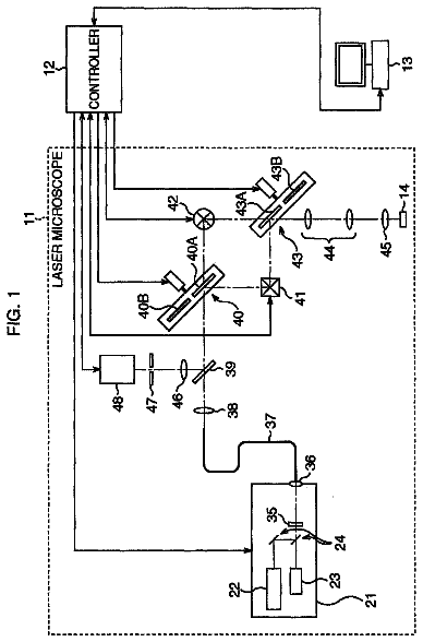
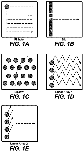
The embodiments of this invention use a multi-point scanning geometry.
US 8,773,771 B2 · Assignee: Olympus Corporation · Inventors: Abe; Kenichiro
Sheet 1 of 22 from the published document. All sheets in the USPTO PDF
An image pickup optical system having four lenses includes in order from an object side, a first lens having a biconvex shape, and a positive refractive power, a second lens having a biconcave shape, and a negative refractive power, a third lens having a meniscus shape with a concave surface thereof directed toward the object side, and a positive refractive power, and a fourth lens having a biconcave shape, and a negative refractive power, and a diaphragm is disposed nearest to the object side, and the surface on the object side of the fourth lens does not have a point of inflection as well as the optical system satisfying the recited numerical conditions.
In recent years, with a thinning of equipments such as a mobile telephone, a portable terminal, and a personal computer, a camera module in which, a length of an optical system in an optical axial direction is thinned to the minimum has been sought. In order to fulfill the requirement, a large number of optical systems with a single focal length, which include about two to three aspheric lenses, have been proposed. Moreover, in recent years, with the technological development of an image pickup element and the increasing needs of the market, a camera module which is small as well as has a large number of pixels, wide angle, and low-cost, has been sought. As an optical system in which, shortening of an overall length of the optical system is facilitated while improving an image forming performance, an optical system proposed in Japanese Patent No. 4317933 and optical systems proposed in J
1 of 22 drawing sheets so far from the published document, cropped to the drawing. Every sheet is in the USPTO PDF.
What the patent claimed, word for word. All of it is now free to use.
The present application is based upon and claims the benefit of priority from the prior Japanese Patent Application No. 2010-94000 filed on Apr. 15, 2010; the entire contents of which are incorporated herein by reference.
The present invention relates to an image pickup optical system and an image pickup apparatus using the same.
In recent years, with a thinning of equipments such as a mobile telephone, a portable terminal, and a personal computer, a camera module in which, a length of an optical system in an optical axial direction is thinned to the minimum has been sought. In order to fulfill the requirement, a large number of optical systems with a single focal length, which include about two to three aspheric lenses, have been proposed.
Moreover, in recent years, with the technological development of an image pickup element and the increasing needs of the market, a camera module which is small as well as has a large number of pixels, wide angle, and low-cost, has been sought. As an optical system in which, shortening of an overall length of the optical system is facilitated while improving an image forming performance, an optical system proposed in Japanese Patent No. 4317933 and optical systems proposed in Japanese Patent Application Laid-open Publication Nos. 2008-268946 and 2009-169005, in which, the number of lenses is let to be four, are available.
These optical systems use four lenses and correct a chromatic aberration favorably for improving a resolution for a large number of pixels while having a small size.
An image pickup optical system according to the present invention having four lenses, includes in order from an object side
a first lens having a biconvex shape, and a positive refractive power,
a second lens having a biconcave shape, and a negative refractive power,
a third lens having a meniscus shape with a concave surface thereof directed toward the object side, and a positive refractive power, and
a fourth lens having a biconcave shape, and a negative refractive power, and
a diaphragm is disposed nearest to the object side, and
the image pickup optical system satisfies the following conditional expressions -0.9<f4/f<0
-0.04<(r8+r9)/(r8-r9)<1.3
where,
f4 denotes a focal length at a near-axis of the fourth lens,
f denotes a focal length of the overall image pickup optical system,
r8 denotes a radius of curvature of a surface on the object side of the fourth lens, and
r9 denotes a radius of curvature of a surface on an image side of the fourth lens.
FIG. 1 is a cross-sectional view along an optical axis showing an optical arrangement at the time of infinite object point focusing of an image pickup optical system according to a first embodiment of the present invention;
FIG. 2 is a diagram showing a spherical aberration (SA) an astigmatism (AS), a distortion (DT), and a chromatic aberration of magnification (CC) at the time of infinite object point focusing of the image pickup optical system according to the first embodiment;
FIG. 3 is a cross-sectional view along an optical axis showing an optical arrangement at the time of infinite object point focusing of an image pickup optical system according to a second embodiment of the present invention;
FIG. 4 is a diagram showing a spherical aberration (SA), an astigmatism (AS), a distortion (DT), and a chromatic aberration of magnification (CC) at the time of infinite object point focusing of the image pickup optical system according to the second embodiment;
FIG. 5 is a cross-sectional view along an optical axis showing an optical arrangement at the time of infinite object point focusing of an image pickup optical system according to a third embodiment of the present invention;
FIG. 6 is a diagram showing a spherical aberration (SA), an astigmatism (AS), a distortion (DT), and a chromatic aberration of magnification (CC) at the time of infinite object point focusing of the image pickup optical system according to the third embodiment;
FIG. 7 is a cross-sectional view along an optical axis showing an optical arrangement at the time of infinite object point focusing of an image pickup optical system according to a fourth embodiment of the present invention;
FIG. 8 is a diagram showing a spherical aberration (SA), an astigmatism (AS), a distortion (DT), and a chromatic aberration of magnification (CC) at the time of infinite object point focusing of the image pickup optical system according to the fourth embodiment;
FIG. 9 is a cross-sectional view along an optical axis showing an optical arrangement at the time of infinite object point focusing of an image pickup optical system according to a fifth embodiment of the present invention;
FIG. 10 is a diagram showing a spherical aberration (SA), an astigmatism (AS), a distortion (DT), and a chromatic aberration of magnification (CC) at the time of infinite object point focusing of the image pickup optical system according to the fifth embodiment;
FIG. 11 is a cross-sectional view along an optical axis showing an optical arrangement at the time of infinite object point focusing of an image pickup optical system according to a sixth embodiment of the present invention;
FIG. 12 is a diagram showing a spherical aberration (SA), an astigmatism (AS), a distortion (DT), and a chromatic aberration of magnification (CC) at the time of infinite object point focusing of the image pickup optical system according to the sixth embodiment;
FIG. 13 is a cross-sectional view along an optical axis showing an optical arrangement at the time of infinite object point focusing of an image pickup optical system according to a seventh embodiment of the present invention;
FIG. 14 is a diagram showing a spherical aberration (SA), an astigmatism (AS), a distortion (DT), and a chromatic aberration of magnification (CC) at the time of infinite object point focusing of the image pickup optical system according to the seventh embodiment;
FIG. 15 is a cross-sectional view along an optical axis showing an optical arrangement at the time of infinite object point focusing of an image pickup optical system according to an eighth embodiment of the present invention;
FIG. 16 is a diagram showing a spherical aberration (SA), an astigmatism (AS), a distortion (DT), and a chromatic aberration of magnification (CC) at the time of infinite object point focusing of the image pickup optical system according to the eighth embodiment;
FIG. 17 is a cross-sectional view along an optical axis showing an optical arrangement at the time of infinite object point focusing of an image pickup optical system according to a ninth embodiment of the present invention;
FIG. 18 is a diagram showing a spherical aberration (SA), an astigmatism (AS), a distortion (DT), and a chromatic aberration of magnification (CC) at the time of infinite object point focusing of the image pickup optical system according to the ninth embodiment;
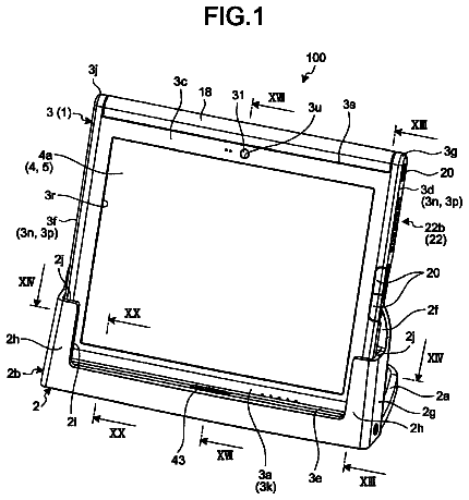
FIG. 19 is a front perspective view of a state in which, a cover of a personal computer 300 which is an example of an information processing apparatus in which, the image pickup optical system of the present invention has been built-in as an objective optical system, is opened;
FIG. 20 is a cross-sectional view of a photographic optical system 303 of the personal computer 300;
FIG. 21 is a side view of the personal computer 300; and
FIG. 22A is a front perspective view of a mobile telephone 400 which is an example of an information processing apparatus in which, the image pickup optical system of the present invention has been built-in as a photographic optical system, FIG. 22B is a side view of the mobile telephone 400, and FIG. 22C is a cross-sectional view of a photographic optical system 405.
First of all, prior to description of embodiments, an action and an effect of an image pickup optical system according to the present invention will be described below.
An image pickup optical system having four lenses, includes in order from an object side
a first lens having a biconvex shape, and a positive refractive power,
a second lens having a biconcave shape, and negative refractive power,
a third lens having a meniscus shape with a concave surface thereof directed toward the object side, and a positive refractive power, and
a fourth lens having a biconcave shape, and a negative refractive power, and
a diaphragm is disposed nearest to the object side, and
the image pickup optical system satisfies the following conditional expressions -0.9<f4/f<0
-0.04<(r8+r9)/(r8-r9)<1.3
where,
f4 denotes a focal length at a near-axis of the fourth lens,
f denotes a focal length of the overall image pickup optical system,
r8 denotes a radius of curvature of a surface on the object side of the fourth lens, and
r9 denotes a radius of curvature of a surface on an image side of the fourth lens.
By disposing a position of a principal point on the object side of the image pickup optical system, since it is possible to make an overall length of the image pickup optical system sufficiently small with respect to a focal length, and shortening of the overall length can be realized.
Moreover, by disposing the diaphragm nearest to the object side, it is possible to keep an exit pupil away from an image plane. Accordingly, it is possible to make small an angle of light rays which are incident on a peripheral portion of an image pickup element. As a result, it becomes possible to avoid degradation of (decrease in) an oblique incident light in the peripheral area of the image pickup element.
Conditional expression
regulates a favorable condition for securing sufficient back focal length while shortening the overall length.
When an upper limit value in conditional expression
is surpassed, since the negative refractive power of the fourth lens becomes weak, and it becomes difficult to position the position of the principal point on the object side of the image pickup optical system. Therefore, shortening of the overall length of the image pickup optical system becomes difficult.
When a lower limit value in conditional expression
is surpassed, since the negative refractive power of the fourth lens becomes large, and it becomes difficult to secure the back focal length sufficiently when an angle of field of the image pickup optical system is widened.
Conditional expression
regulates a condition which is favorable for avoiding decrease in peripheral light amount and for widening an angle of field. Further, by suppressing an exit angle of light rays from a surface on the image side of the fourth lens, degradation of peripheral light amount could be avoided. Accordingly, conditional expression
regulates a condition which is favorable for suppressing an exit angle of light rays from a surface on the image side of the fourth lens and for widening an angle of field. Further, an avoidance of peripheral light amount includes a state where degradation of peripheral light amount could be reduced even when an F value (F-number) of the lens is made brighter.
When a lower limit value in conditional expression
is surpassed, a curvature on the image side of the fourth lens becoming excessively large. In this case, an exit angle of off-axis light beam from the surface on the image side of the fourth lens becomes steep. As a result, since an angle of light rays which are incident on a peripheral portion of the image pickup element becomes large, and it becomes difficult to avoid degradation of the peripheral light amount. Furthermore, when a lower limit value in conditional expression
is surpassed, correction of a coma aberration becomes difficult.
When an upper limit value in conditional expression
is surpassed, a principal point of the fourth lens is positioned toward the object side, since a negative curvature on the object side of the fourth lens becoming excessively large. Therefore, widening of the angle of field and shortening of combined focal length of the overall image pickup optical system becomes difficult.
Moreover, it is preferable that the image pickup optical system of the present invention satisfies the following conditional expression (1') instead of conditional expression (1). -0.72<f4/f<-0.22 (1')
Furthermore, it is more preferable that the image pickup optical system of the present invention satisfies the following conditional expression (1'') instead of conditional expression (1). -0.62<f4/f<-0.31 (1'')
Moreover, it is preferable that the image pickup optical system of the present invention satisfies the following conditional expression (2') instead of conditional expression (2). 0.38<(r8+r9)/(r8-r9)<1.1 (2')
Furthermore, it is more preferable that the image pickup optical system of the present invention satisfies the following conditional expression (2'') instead of conditional expression (2). 0.55<(r8+r9)/(r8-r9)<0.9 (2'')
In the image pickup optical system of the present invention, it is desirable that the surface on the object side of the fourth lens does not have a point of inflection. By suppressing a change in curvature of a lens surface at an off-axis, it is possible to suppress a variation in a curvature of field due to an image pickup distance, and moreover, it is possible to suppress degradation of performance due to a manufacturing error.
In the image pickup optical system of the present invention, it is desirable that the surface on the object side of the fourth lens is a spherical surface. Accordingly, since it is possible to make small an angle of incidence of the off-axis light beam on the surface on the object side of the fourth lens, and to minimize an occurrence of the coma aberration. Moreover, by making the curvature constant from axial to peripheral area, it is possible to minimize degradation of performance due to a manufacturing error.
In the image pickup optical system of the present invention, it is desirable that a half angle of field .omega. is in the following range. 30.degree.<.omega.<60.degree. (A)
It is desirable that the image pickup optical system of the present invention satisfies the following conditional expression. 0.08<(r2+r3)/(r2-r3)<0.42
where,
r2 denotes a radius of curvature of a surface on the object side of the first lens, and
r3 denotes a radius of curvature of a surface on the image side of the first lens.
Conditional expression
regulates a preferable shape of the first lens.
When a lower limit value in conditional expression
is surpassed, the radius of curvature on the object side of the first lens becomes small. In this case, since an angle of incidence of light rays on the surface on the object side of the first lens becomes steep, correction of coma aberration becomes difficult. Particularly, when an attempt is made to maintain the half angle of field in the range in conditional expression (A), the correction of coma aberration becomes difficult.
When an upper limit value in conditional expression
is surpassed, the radius of curvature on the object side of the first lens becomes large, and conversely, curvature on the image side becomes strong. Therefore, it becomes difficult to position the principal point toward the object side in the overall image pickup optical system. As a result, shortening of the overall image pickup optical system becomes difficult.
It is preferable that the image pickup optical system of the present invention satisfies the following conditional expression (3') instead of conditional expression (3). 0.11<(r2+r3)/(r2-r3)<0.31 (3')
Furthermore, it is more preferable that the image pickup optical system of the present invention satisfies the following conditional expression (3'') instead of conditional expression (3). 0.14<(r2+r3)/(r2-r3)<0.27 (3'')
Moreover, in the image pickup optical system of the present invention, it is desirable that an Fno (F value) is in the following range. 2.0<Fno<2.8 (B)
It is desirable that the image pickup optical system of the present invention satisfies the following conditional expression (C). 0.01<1/.nu.2-1/.nu.1<0.03 (C)
where,
.nu.1 denotes Abbe's number (nd1-1)/(nF1-nC1) for the first lens,
.nu.2 denotes Abbe's number (nd2-1)/(nF2-nC2) for the second lens,
where,
nd1, nC1, nF1, and ng1 denote refractive indices for a d-line, a C-line, an F-line, and a g-line respectively of the first lens, and
nd2, nC2, nF2, and ng2 denote refractive indices for the d-line, the C-line, the F-line, and the g-line respectively of the second lens.
Conditional expression (C) is a relational expression relating Abbe's number for the first lens and Abbe's number for the second lens. By satisfying conditional expression (C), it is possible to correct a chromatic aberration favorably.
Moreover, it is desirable that the image pickup optical system of the present invention satisfies the following conditional expression. -0.03<(r4+r5)/(r4-r5)<0.55
where,
r4 denotes a radius of curvature of a surface on the object side of the second lens, and
r5 denotes a radius of curvature of a surface on the image side of the second lens.
Conditional expression
regulates a shape of the second lens.
When a lower limit value in conditional expression
is surpassed, the radius of curvature on the image side of the second lens becomes large. In this case, it is not possible to make large an exit angle of light rays from the second lens when light rays are emerged from the second lens. As a result, it becomes difficult to achieve the shortening of the image pickup optical system and securing of the telecentricity simultaneously. Particularly, when an attempt is made to satisfy conditional expression (C) upon maintaining the half angle of field in the range of conditional expression (A), it becomes difficult to achieve the shortening of the image pickup optical system and securing of the telecentricity simultaneously.
When an upper limit value in conditional expression
is surpassed, the radius of curvature on the object side of the second lens becomes large. Therefore, correction of a spherical aberration which has occurred at the first lens becomes insufficient. Particularly, when an attempt is made to maintain the F value in the range of conditional expression (B), correction of the coma aberration becomes difficult.
It is preferable that the image pickup optical system of the present invention satisfies the following conditional expression (4') instead of conditional expression (4). 0.10<(r4+r5)/(r4-r5)<0.41 (4')
Furthermore, it is more preferable that the image pickup optical system of the present invention satisfies the following conditional expression (4'') instead of conditional expression (4). 0.16<(r4+r5)/(r4-r5)<0.36 (4'')
Moreover, it is desirable that the image pickup optical system of the present invention satisfies the following conditional expression. 0.97<(r6+r7)/(r6-r7)<1.52
where,
r6 denotes a radius of curvature of a surface on the object side of the third lens, and
r7 denotes a radius of curvature of a surface on the image side of the third lens.
Conditional expression
regulates a condition which is favorable for suppressing an angle of incidence of light rays on the surface on the object side and the image side of the third lens, and corrects the coma aberration favorably, as well as, regulates a condition for realizing shortening the overall length of the image pickup optical system while maintaining the telecentricity of the image pickup optical system.
Further, by suppressing the angle of incidence of light rays on the surface on the object side and the image side of the third lens, the coma aberration could be corrected favorably.
Accordingly, conditional expression
regulates a condition which is favorable for the angle of incidence of light rays on the surface on the object side and the image side of the third lens and for realizing shortening the overall length of the image pickup optical system while maintaining the telecentricity of the image pickup optical system.
When an upper limit value in conditional expression
is surpassed, the negative curvature on the object side and the image side of the third lens becomes excessively small. In this case, when an off-axis light ray is incident on the surface on the object side and the image side of the third lens, since an angle of incidence of an off-axis light beam becomes steep, correction of the coma aberration becomes difficult.
When a lower limit value in conditional expression
is surpassed, since the negative curvature on the image side of the third lens becoming excessively large, when light beam is emerged from the third lens, an exit angle from the third lens becomes small. Therefore, it becomes difficult to achieve the shortening of the overall length of the image pickup optical system and securing of the telecentricity simultaneously.
It is preferable that the image pickup optical system of the present invention satisfies the following conditional expression (5') instead of conditional expression (5). 1.10<(r6+r7)/(r6-r7)<1.47 (5')
It is more preferable that the image pickup optical system of the present invention satisfies the following conditional expression (5'') instead of conditional expression (5). 1.34<(r6+r7)/(r6-r7)<1.40 (5'')
Moreover, in the image pickup optical system of the present invention, it is desirable that the first lens, the second lens, the third lens, and the fourth lens are formed of a resin.
By using a resin, it is possible to provide a low-cost image pickup optical system.
According to another preferable aspect of the present invention, an image pickup apparatus of the present invention includes
an image pickup optical system which has been described above, and
an electronic image pickup element having an image pickup surface, and
the image pickup apparatus satisfies the following conditional expression. 15.degree.<.alpha.i<30.degree.
where,
.alpha. denotes an angle of incidence of a principal light ray on the image pickup surface, at the maximum image height.
In a case of using a CCD (charge coupled device) for a solid image pickup element, when off-axis light beam (off-axis chief ray) emerged from an optical system is incident on an image pickup surface making a large angle, brightness of image changes in a central portion and a peripheral portion of the image. Moreover, when the angle of incidence on the image pickup surface is small, the problem of change in brightness is solved but the overall length of the optical system becomes long. Therefore, it is desirable that the image pickup optical system satisfies conditional expression (6).
Moreover, according still another preferable aspect of the present invention, it is desirable that the image pickup apparatus includes an auto-focus mechanism which is integrated with the image pickup optical element.
By installing the auto-focus mechanism, it is possible to focus at any object distance.
Moreover, according to still another preferable aspect of the present invention, it is desirable that in the image pickup apparatus, the image pickup optical system and the electronic image pickup element are integrated.
By integrating the image pickup optical system and the electronic image pickup element, it is possible to convert an optical image captured by the image pickup optical system to an electric signal. Moreover, by selecting an electronic image pickup element which is capable of reducing a change (difference) in a brightness of an image in a central portion and a peripheral portion of the image by .alpha.i, it is possible to provide an image pickup apparatus having a small size and an improved performance.
Exemplary embodiments of an image pickup optical system and an image pickup apparatus according to the present invention will be described below in detail by referring to the accompanying diagrams. However, the present invention is not restricted to the embodiments described below.
To start with, an image pickup optical system according to a first embodiment of the present invention will be described below. FIG. 1 is a cross-sectional view along an optical axis showing an optical arrangement at the time of infinite object point focusing of the image pickup optical system according to the first embodiment.
FIG. 2 is a diagram showing a spherical aberration (SA), an astigmatism (AS), a distortion (DT), and a chromatic aberration of magnification (CC) at the time of infinite object point focusing of the image pickup optical system according to the first embodiment. Moreover, FIY denotes an image height. Symbols in aberration diagrams are same in the embodiments that will be described later.
The image pickup optical system of the first embodiment, as shown in FIG. 1, includes in order from an object side, an aperture stop S, a first lens L1 having a positive refractive power, a second lens L2 having a negative refractive power, a third lens L3 having a positive refractive power, and a fourth lens L4 having a negative refractive power. In all the embodiments that will be described below, in lens cross-sectional views, CG denotes a cover glass, and I denotes an image pickup surface of an electronic image pickup element.
The first lens L1 is a biconvex positive lens. The second lens L2 is a biconcave negative lens. The third lens L3 is a positive meniscus lens having a concave surface directed toward the object side. The fourth lens L4 is a biconcave negative lens.
An aspheric surface is provided to seven surfaces namely, both surfaces of each of the first lens L1, the second lens L2, and the third lens L3, and a surface on an image side of the fourth lens L4.
Next, an image pickup optical system according to a second embodiment of the present invention will be described below. FIG. 3 is a cross-sectional view along an optical axis showing an optical arrangement at the time of infinite object point focusing of the image pickup optical system according to the second embodiment.
FIG. 4 is a diagram showing a spherical aberration (SA), an astigmatism (AS), a distortion (DT), and a chromatic aberration of magnification (CC) at the time of infinite object point focusing of the image pickup optical system according to the second embodiment.
The image pickup optical system of the second embodiment, as shown in FIG. 3, includes in order from an object side, an aperture stop S, a first lens L1 having a positive refractive power, a second lens L2 having a negative refractive power, a third lens L3 having a positive refractive power, and a fourth lens L4 having a negative refractive power.
The first lens L1 is a biconvex positive lens. The second lens L2 is a biconcave negative lens. The third lens L3 is a positive meniscus lens having a concave surface directed toward the object side. The fourth lens L4 is a biconcave negative lens.
An aspheric surface is provided to seven surfaces namely, both surfaces of each of the first lens L1, the second lens L2, and the third lens L3, and a surface on an image side of the fourth lens L4.
Next, an image pickup optical system according to a third embodiment of the present invention will be described below. FIG. 5 is a cross-sectional view along an optical axis showing an optical arrangement at the time of infinite object point focusing of the image pickup optical system according to the third embodiment.
FIG. 6 is a diagram showing a spherical aberration (SA), an astigmatism (AS), a distortion (DT), and a chromatic aberration of magnification (CC) at the time of infinite object point focusing of the image pickup optical system according to the third embodiment.
The image pickup optical system of the third embodiment, as shown in FIG. 5, includes in order from an object side, an aperture stop S, a first lens L1 having a positive refractive power, a second lens L2 having a negative refractive power, a third lens L3 having a positive refractive power, and a fourth lens L4 having a negative refractive power.
The first lens L1 is a biconvex positive lens. The second lens L2 is a biconcave negative lens. The third lens L3 is a positive meniscus lens having a concave surface directed toward the object side. The fourth lens L4 is a biconcave negative lens.
An aspheric surface is provided to seven surfaces namely, both surfaces of each of the first lens L1, the second lens L2, and the third lens L3, and a surface on an image side of the fourth lens L4.
Next, an image pickup optical system according to a fourth embodiment of the present invention will be described below. FIG. 7 is a cross-sectional view along an optical axis showing an optical arrangement at the time of infinite object point focusing of the image pickup optical system according to the fourth embodiment.
FIG. 8 is a diagram showing a spherical aberration (SA), an astigmatism (AS), a distortion (DT), and a chromatic aberration of magnification (CC) at the time of infinite object point focusing of the image pickup optical system according to the fourth embodiment.
The image pickup optical system of the fourth embodiment, as shown in FIG. 7, includes in order from an object side, an aperture stop S, a first lens L1 having a positive refractive power, a second lens L2 having a negative refractive power, a third lens L3 having a positive refractive power, and a fourth lens L4 having a negative refractive power.
The first lens L1 is a biconvex positive lens. The second lens L2 is a biconcave negative lens. The third lens L3 is a positive meniscus lens having a concave surface directed toward the object side. The fourth lens L4 is a biconcave negative lens.
An aspheric surface is provided to seven surfaces namely, both surfaces of each of the first lens L1, the second lens L2, and the third lens L3, and a surface on an image side of the fourth lens L4.
Next, an image pickup optical system according to a fifth embodiment of the present invention will be described below. FIG. 9 is a cross-sectional view along an optical axis showing an optical arrangement at the time of infinite object point focusing of the image pickup optical system according to the fifth embodiment.
FIG. 10 is a diagram showing a spherical aberration (SA), an astigmatism (AS), a distortion (DT), and a chromatic aberration of magnification (CC) at the time of infinite object point focusing of the image pickup optical system according to the fifth embodiment.
The image pickup optical system of the fifth embodiment, as shown in FIG. 9, includes in order from an object side, an aperture stop S, a first lens L1 having a positive refractive power, a second lens L2 having a negative refractive power, a third lens L3 having a positive refractive power, and a fourth lens L4 having a negative refractive power.
The first lens L1 is a biconvex positive lens. The second lens L2 is a biconcave negative lens. The third lens L3 is a positive meniscus lens having a concave surface directed toward the object side. The fourth lens L4 is a biconcave negative lens.
An aspheric surface is provided to seven surfaces namely, both surfaces of each of the first lens L1, the second lens L2, and the third lens L3, and a surface on an image side of the fourth lens L4.
Next, an image pickup optical system according to a sixth embodiment of the present invention will be described below. FIG. 11 is a cross-sectional view along an optical axis showing an optical arrangement at the time of infinite object point focusing of the image pickup optical system according to the sixth embodiment.
FIG. 12 is a diagram showing a spherical aberration (SA), an astigmatism (AS), a distortion (DT), and a chromatic aberration of magnification (CC) at the time of infinite object point focusing of the image pickup optical system according to the sixth embodiment.
The image pickup optical system of the sixth embodiment, as shown in FIG. 11, includes in order from an object side, an aperture stop S, a first lens L1 having a positive refractive power, a second lens L2 having a negative refractive power, a third lens L3 having a positive refractive power, and a fourth lens L4 having a negative refractive power.
The first lens L1 is a biconvex positive lens. The second lens L2 is a biconcave negative lens. The third lens L3 is a positive meniscus lens having a concave surface directed toward the object side. The fourth lens L4 is a biconcave negative lens.
An aspheric surface is provided to seven surfaces namely, both surfaces of each of the first lens L1, the second lens L2, and the third lens L3, and a surface on an image side of the fourth lens L4.
Next, an image pickup optical system according to a seventh embodiment of the present invention will be described below. FIG. 13 is a cross-sectional view along an optical axis showing an optical arrangement at the time of infinite object point focusing of the image pickup optical system according to the seventh embodiment.
FIG. 14 is a diagram showing a spherical aberration (SA), an astigmatism (AS), a distortion (DT), and a chromatic aberration of magnification (CC) at the time of infinite object point focusing of the image pickup optical system according to the seventh embodiment.
The image pickup optical system of the seventh embodiment, as shown in FIG. 13, includes in order from an object side, an aperture stop S, a first lens L1 having a positive refractive power, a second lens L2 having a negative refractive power, a third lens L3 having a positive refractive power, and a fourth lens L4 having a negative refractive power.
The first lens L1 is a biconvex positive lens. The second lens L2 is a biconcave negative lens. The third lens L3 is a positive meniscus lens having a concave surface directed toward the object side. The fourth lens L4 is a biconcave negative lens.
An aspheric surface is provided to seven surfaces namely, both surfaces of each of the first lens L1, the second lens L2, and the third lens L3, and a surface on an image side of the fourth lens L4.
Next, an image pickup optical system according to an eighth embodiment of the present invention will be described below. FIG. 15 is a cross-sectional view along an optical axis showing an optical arrangement at the time of infinite object point focusing of the image pickup optical system according to the eighth embodiment.
FIG. 16 is a diagram showing a spherical aberration (SA), an astigmatism (AS), a distortion (DT), and a chromatic aberration of magnification (CC) at the time of infinite object point focusing of the image pickup optical system according to the eighth embodiment.
The image pickup optical system of the eighth embodiment, as shown in FIG. 15, includes in order from an object side, an aperture stop S, a first lens L1 having a positive refractive power, a second lens L2 having a negative refractive power, third lens L3 having a positive refractive power, and a fourth lens L4 having a negative refractive power.
The first lens L1 is a biconvex positive lens. The second lens L2 is a biconcave negative lens. The third lens L3 is a positive meniscus lens having a concave surface directed toward the object side. The fourth lens L4 is a biconcave negative lens.
An aspheric surface is provided to seven surfaces namely, both surfaces of each of the first lens L1, the second lens L2, and the third lens L3, and a surface on an image side of the fourth lens L4.
Next, an image pickup optical system according to a ninth embodiment of the present invention will be described below. FIG. 17 is a cross-sectional view along an optical axis showing an optical arrangement at the time of infinite object point focusing of the image pickup optical system according to the ninth embodiment.
FIG. 18 is a diagram showing a spherical aberration (SA), an astigmatism (AS), a distortion (DT), and a chromatic aberration of magnification (CC) at the time of infinite object point focusing of the image pickup optical system according to the ninth embodiment.
The image pickup optical system of the ninth embodiment, as shown in FIG. 17, includes in order from an object side, an aperture stop S, a first lens L1 having a positive refractive power, a second lens L2 having a negative refractive power, a third lens L3 having a positive refractive power, and a fourth lens L4 having a negative refractive power.
The first lens L1 is a biconvex positive lens. The second lens L2 is a biconcave negative lens. The third lens L3 is a positive meniscus lens having a concave surface directed toward the object side. The fourth lens L4 is a biconcave negative lens.
An aspheric surface is provided to eight surfaces namely, both surfaces of each of the first lens L1, the second lens L2, the third lens L3, and the fourth lens L4.
Numerical data of each embodiment described above is shown below. Apart from symbols described above, each of r1, r2, . . . denotes radius of curvature of each lens surface, each of d1, d2, . . . denotes a distance between two lenses, each of nd1, nd2, . . . denotes a refractive index of each lens for a d-line, each of .nu.d1, .nu.d2, denotes an Abbe constant for each lens, F.sub.NO denotes an F number, f denotes a focal length of the entire zoom lens system, .omega. denotes a half angle of field, and further, * denotes an aspheric data, S denotes an aperture stop.
When z is let to be an optical axis with a direction of traveling of light as a positive (direction), and y is let to be in a direction orthogonal to the optical axis, a shape of the aspheric surface is described by the following expression. z=(y.sup.2/r)/[1+{1-(K+1)(y/r).sup.2}.sup.1/2]+A.sub.4y.sup.4+A6y.sup.6+A- 8y.sup.8+A.sup.10y.sup.10+A12y.sup.12
where, r denotes a paraxial radius of curvature, K denotes a conical coefficient, A4, A6, A8, A10, and A12 denote aspherical surface coefficients of a fourth order, a sixth order, an eight order, a tenth order, and a twelfth order respectively. Moreover, in the aspherical surface coefficients, `e-n` (where, n is an integral number) indicates `10.sup.-n`.
These symbols are used in common in the following examples.
TABLE-US-00001 Unit mm Surface data Surface no. r d nd .nu.d Object plane .infin. .infin. 1(S) .infin. -0.03 2* 2.235 0.80 1.53368 55.90 3* -1.459 0.05 4* -3.364 0.40 1.58366 30.31 5* 2.059 0.45 6* -3.775 0.74 1.53368 55.90 7* -0.622 0.11 8 -7.340 0.40 1.53368 55.90 9* 0.798 0.68 10 .infin. 0.30 1.51633 64.14 11 .infin. 0.28 Image plane(Light receiving surface) .infin. 0. Aspherical surface data 2nd surface K = 1.770 A4 = -7.72783e-02, A6 = -3.40091e-02, A8 = -2.24696e-01, A10 = 1.05804e-01, A12 = -2.34225e-02 3rd surface K = -11.405 A4 = -3.61371e-01, A6 = 3.50779e-01, A8 = -2.23847e-01, A10 = -2.79617e-02, A12 = -1.79443e-02 4th surface K = -61.495 A4 = -2.53722e-01, A6 = 1.57749e-01, A8 = 2.04292e-01, A10 = -1.70411e-01, A12 = 4.74592e-03 5th surface K = -11.082 A4 = 5.92593e-02, A6 = -7.04438e-02, A8 = 4.27171e-0, A10 = 2.71522e-02, A12 = -1.99514e-02 6th surface K = -3.776 A4 = -1.32189e-01, A6 = 3.49062e-01, A8 = -2.80220e-01, A10 = 7.07615e-02, A12 = 3.45995e-03, A14 = 2.84433e-03, A16 = -6.71436e-03 7th surface K = -3.363 A4 = -2.96456e-01, A6 = 3.31692e-01, A8 = -1.08811e-01, A10 = 1.25186e-02, A12 = 3.50852e-04, A14 = -7.12411e-05, A16 = 1.32893e-04 9th surface K = -7.403 A4 = -8.01002e-02, A6 = 2.17325e-02, A8 = -4.96820e-03, A10 = 4.13531e-04, A12 = -5.04269e-06, A14 = -2.26260e-07, A16 = -9.99010e-07 Various data Focal length 3.00 Fno. 2.5 Image angle .omega. 37.39 Image height 2.291 BF (in air) 1.13 Total lens length (in air) 4.08
The description continues in the full USPTO document.
About 6,523 words. The USPTO PDF has it with every drawing.
Fees are due 3.5, 7.5 and 11.5 years after grant. This patent expired on July 8, 2026, so the fee marked "not paid" was the one that went unpaid.
Image pickup optical system and image pickup apparatus using the same
Filed Apr 2011 · published Oct 2011Image pickup optical system and image pickup apparatus using the same
Filed Apr 2011 · granted Jul 2014Earlier publications, parents and continuations. None of them can still be enforced, or this patent would not be listed.
Prior art cited by the examiner or applicant. Useful when you check your own idea for novelty.
Everything on this page comes from the documents linked above.