Lapsed, fee not paid10 drawings
Cameras, Displays & Optics · US 8,767,308 B2
Negative add liquid meniscus lens
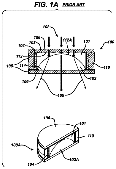
The present invention relates generally to an arcuate liquid meniscus lens with a meniscus wall.
US 8,767,310 B2 · Assignee: Olympus Imaging Corp. · Inventors: Ogata; Yasuji et al.
Sheet 1 of 25 from the published document. All sheets in the USPTO PDF
The invention provides a zoom lens, characterized by comprising, a zoom lens, which comprises, in order from an object side thereof: a first lens group of negative refracting power, a second lens group of positive refracting power, a third lens group of negative refracting power, and a fourth lens group of positive refracting power, wherein: upon zooming from a wide-angle end to a telephoto end of the zoom lens, a separation between the respective lens groups changes, upon focusing from a focusing-on-infinity state to a close-range focusing state, the third lens group moves in an optical axis direction, and the conditions (1) and (2) are satisfied at the wide-angle end.
So far, some digital camera products have been known to be capable of taking moving images. In recent years, interchangeable type digital cameras, especially an interchangeable lens compatible with the function of the camera body of taking moving images have also been under study. Only the requirement for conventional cameras designed to take still images has been that they are in focus on target subjects in the moment of image shooting after determination of the composition, because their object has been not to miss blink-of-an-eye shutter chances. For instance, the so-called autofocus (AF) function has been adopted because of its combined high speed/accuracy. In the taking of moving images with some video cameras designed for professional use, on the other hand, a skilled cameraman has implemented focusing operation in the manual focus (MF) mode. For many consumer-oriented video camera
1 of 25 drawing sheets so far from the published document, cropped to the drawing. Every sheet is in the USPTO PDF.
What the patent claimed, word for word. All of it is now free to use.
So far, some digital camera products have been known to be capable of taking moving images. In recent years, interchangeable type digital cameras, especially an interchangeable lens compatible with the function of the camera body of taking moving images have also been under study.
Only the requirement for conventional cameras designed to take still images has been that they are in focus on target subjects in the moment of image shooting after determination of the composition, because their object has been not to miss blink-of-an-eye shutter chances. For instance, the so-called autofocus (AF) function has been adopted because of its combined high speed/accuracy.
In the taking of moving images with some video cameras designed for professional use, on the other hand, a skilled cameraman has implemented focusing operation in the manual focus (MF) mode. For many consumer-oriented video cameras, however, it is required to put the AF system constantly in operation thereby keeping an in-focus state depending on object distances. To this end, the contrast AF mode (the so-called climbing mode) relying upon an imaging device has been adopted.
Further, to keep the in-focus state, the focus lens is constantly subjected to back-and-fore, minute movement (called wobbling) in the optical axis direction to measure contrast changes. As the in-focus state is judged as being changing, it causes the focus lens to be properly moved for re-focusing operation. This wobbling function requires very fast operation depending on frame rates; so there is still mounting demand for reducing the weight of a lens used for wobbling.
The range of movement of the constantly moving focus lens remains within the depth of focus. Accordingly, it is controlled such that any out-of-focus state during wobbling cannot be recognized; however, when there is a large image magnification change, images look quite unnatural because they look as if they were always waving. Accordingly, it is still a vital requirement to reduce or minimize the magnification changes during wobbling.
Further, as there is a large change in the focus sensitivity (the amount of movement of the image plane per unit amount of movement of the lens) of the wobbling lens during zooming, it gives rise to a large difference in the amount of movement required for the wobbling lens at the wide-angle and telephoto ends, resulting in difficulty in control of fast and minute movement. It is therefore desired that the amount of change in the focus sensitivity of the wobbling lens be reduced as much as possible.
Patent Publication 1 has come up with a design example for small-format, less costly telephoto zoom lenses. According to the teachings, a positive-negative-positive three-groups zoom type is adopted and focusing is implemented at the second lens group, thereby making it possible to set up a small-format, less costly telephoto zoom lens with fewer lenses.
Patent Publication 2, and Patent Publication 3 has proposed a zoom lens finding an interchangeable lens system application for digital cameras with the taking of moving image in mind. With the zoom lens proposed in Patent Publication 2, focusing is implemented with fewer lenses.
For the negative power-leadoff type zoom lenses designed typically for size and cost reductions, on the other hand, such zoom lenses as set forth in Patent Publications 4, 5 and 6 have been known so far in the art. These are zoom lenses that are well fit for compact cameras and achieve a zoom ratio of the order of 3 with fewer lenses. They are operated in the rear focusing mode involving movement of one lens.
However, the zoom lens set forth in Patent Publication 1 is far away from being suitable for the taking of moving images because of too large image magnification changes during wobbling. In the zoom lenses set forth in Patent Publications 2 and 3, there is a fairly large number of lens groups used, which is apt to result not only in the need for using a lot more lenses, but also in bulkier size and higher costs.
The first aspect of the invention has been achieved with the above problems in mind, and has for its object to provide a negative-positive-negative-positive four-groups zoom lens favorable for small-format telephoto zoom lenses and having a screen easy to view during wobbling. Another object of the first aspect of the invention is to provide a zoom lens making it easy for an operator to view images during wobbling operation.
It is thus possible to provide a zoom lens that finds applications as an interchangeable lens system for digital cameras, is well compatible with the function of taking moving images, enables wobbling, and works more in favor of size and cost reductions. Yet another object of the first aspect of the invention is to provide an imaging apparatus equipped with such a zoom lens.
Referring again to the zoom lens disclosed in Patent Publication 2, its size is apt to grow large because it is a telephoto zoom lens of the positive power-leadoff type.
Referring again to the zoom lenses disclosed in Patent Publications 4 and 5, the taking of moving images is factored out, so intentional wobbling would result in large magnification changes and the inability to take moving images.
The second aspect of the invention has been figured out with the aforesaid problems in mind. One object of the second aspect of the invention is to provide a zoom lens working more in favor of size reductions and having a screen easier to view upon focusing, and another object is to provide a zoom lens easier to view images during wobbling operation. [Patent Publication 1] U.S. Pat. No. 7,450,319 [Patent Publication 2] JP(A) 2000-122620 [Patent Publication 3] U.S. patent application Ser. No. 2009/0251781 [Patent Publication 4] U.S. Pat. No. 7,212,351 [Patent Publication 5] U.S. Pat. No. 7,339,745 [Patent Publication 6] U.S. Pat. No. 7,652,826
To achieve the aforesaid objects, the zoom lens, and the imaging apparatus, according to the first aspect of the invention is carried out in any one of the following embodiments.
According to the first aspect of the invention, there is a zoom lens provided, which comprises, in order from an object side thereof,
a first lens group of positive refracting power,
a second lens group of negative refracting power,
a third lens group of positive refracting power, and
a fourth lens group of negative refracting power,
wherein:
upon zooming from a wide-angle end to a telephoto end of the zoom lens, a separation between the respective lens group changes,
a separation between the first lens group and the second lens group becomes wide, and
a separation between the second lens group and the third lens group grows narrow;
upon focusing from a focusing-on-infinity state to a close-range focusing state,
the fourth lens group moves in an optical axis direction; and
the following Conditions
and
are satisfied at the wide-angle end: |(100*(y1'-y1)/y1)|/.DELTA.s<1.2
|(100*(y0.7'-y0.7)/y0.7)|/.DELTA.s<1.2
where y1 is the maximum image height on an imaging plane,
y0.7 is seven-tenth of the maximum image height,
y1' is a ray height at a position where, when there is a defocus quantity of .DELTA.s from time of focusing on infinity as the fourth lens group is moved to an object at infinity, a chief ray having the same angle of view as an image-taking angle of view reaching the image height y1 upon focusing on infinity intersects the imaging plane,
y0.7' is a ray height at a position where, when there is a defocus quantity of .DELTA.s from time of focusing on infinity as the fourth lens group is moved to an object at infinity, a chief ray having the same angle of view as an image-taking angle of view reaching the image height y0.7 upon focusing on infinity intersects the imaging plane, and
.DELTA.s is 8*the maximum image height y1/1000, provided that y1, y0.7, y1', y0.7' and .DELTA.s are all given in mm.
The requirements for, and the advantages of, the aforesaid arrangement for the zoom lens according to the first aspect of the invention are now explained.
By adoption of the positive power-leadoff type zoom lens where the lens group of positive refracting power is located on the most object side, it is possible to design a lens arrangement preferable as a telephoto zoom lens because it works in favor of making sure the desired zoom ratio and the desired brightness at the telephoto end. Substantial zooming takes place by a separation change between the first and the second lens group and a separation change between the second and the third lens group. In addition, the provision of the fourth lens group of negative refracting power allows the size of the first, second and third lens groups to remain small, working in favor of setting up a small-format, less costly zoom lens.
The first aspect of the invention is well fit for a small-format telephoto zoom lens. With a conventional zoom lens having a positive-negative-positive refracting power layout in order from its object side with the second lens group used as a focusing lens group, it is easy to correct aberration fluctuations in near distances. However, it is difficult to control driving mechanisms because the weight of the focusing lens group is heavy, the sensitivity of the second lens group to focusing changes largely, etc.
There is thus the need for achieving any focusing mode that takes care of the fast driving (plus wobbling in the taking of moving images) of the focusing lens group in the zoom lens; so there is mounting demand for further size reductions of the focusing group. Moreover, to reduce changes in the sensitivity of the focusing lens group to focusing as zooming takes place, it has been found that the focusing lens group should preferably be located on an image side with respect to the third lens group. In the first aspect of the invention, therefore, the fourth lens group of negative refracting power is located on the image side of the third lens group of positive refracting power so that focusing (plus wobbling) is implemented with the fourth lens group. Upon zooming, the third and the fourth lens group may be moved in unison. However, if the separation between these lens groups is made variable, it is then possible to reduce field curvature changes in association with zooming.
The zoom lens of the first aspect of the invention, because of having such an arrangement, enables image magnification changes to be much more reduced than a conventional zoom lens upon focusing (plus wobbling during the taking of moving images). The amount of image magnification changes differs with image heights; that amount cannot fully be reduced only with specific image heights, so it must be reduced throughout the screen.
Conditions
and
are provided for that purpose: they are the ones for determining the amount of image magnification changes relative to the defocus quantity. It is here noted that although differing with the value of defocus quantity .DELTA.s, calculation is made in terms of a defocus quantity equivalent to an allowed depth. Generally, the allowed depth may be represented by F-number*allowed diameter of circle of confusion. In the first aspect of the invention, however, the F-number is supposed to be equal to 8, and the allowed diameter of circle of confusion is supposed to be equal to the maximum image height (y1)/1000.
It may be relatively easy to satisfy either one of Conditions
and (2), but there is the need for satisfying both Conditions
and
so as to reduce the amount of image magnification changes throughout the screen, as contemplated herein. It has now been found that by satisfying both conditions, image magnification changes can be kept small even in other image height states and focal length states. Exceeding the upper limits to Conditions
and
is not preferable because the amount of image magnification changes grows large.
FIG. 1 is illustrative in schematic of the definitions of Conditions
and
for the zoom lens according to the first aspect of the invention. For convenience of illustration, the shape and number of lenses in each of the first to fourth lens groups are simplified, while the amount of movement of, and the optical path through, the fourth lens group supposed to wobble are exaggerated.
The zoom lens according to the first aspect of the invention is built up of, in order from its object side to its image side (imaging plane), a first lens group of positive refracting power, a second lens group of negative refracting power, a third lens group of positive refracting power, and a fourth lens group of negative refracting power.
In FIG. 1, a light ray A is indicative of a chief ray incident on the position of the maximum image height (y1) at the imaging plane upon focusing on infinity, and a light ray B is indicative of a chief ray incident on the position (y0.7) seven-tenth of the maximum image height (y1) at the imaging plane upon focusing on infinity.
The zoom lens according to the first aspect of the invention is characterized in that the fourth lens group is moved for focusing or wobbling. In FIG. 1, a light ray A'is indicative of a displacement of the chief ray A as the fourth lens group is moved by focusing or wobbling to form an image at a position separate away from the imaging plane by the defocus quantity .DELTA.s.
In FIG. 1, a light ray B' is indicative of a displacement of the chief ray B as the fourth lens group is moved by focusing or wobbling to form an image at a position separate away from the imaging plane by the defocus quantity .DELTA.s. It is here noted that the defocus quantity .DELTA.s is supposed to be 8*the maximum image height (y1)/1000.
An image height where the ray A' is imaged at the imaging plane is defined by y1', and an image height where the ray B' is imaged at the imaging plane is defined by y0.7'.
The fourth lens group of negative refracting power works in favor of making sure weight reductions and sensitivity to focusing. In addition, although the separation between the fourth lens group and the image plane grows wide as the fourth lens group is let out, the height of incidence of the chief ray on the fourth lens group off the optical axis becomes so low that magnification changes at the imaging plane are canceled out. Therefore, it is easy to reduce magnification changes in association with the movement of the fourth lens group, and reduce magnification changes upon focusing (plus wobbling) operation. This favors especially the taking of moving images. Thus, the fourth lens group may be set up in the form of not only the focusing group but also the wobbling group that wobbles in the axial direction prior to focusing.
To obtain moving images of high quality on a large-screen TV or the like with stricter conditions imposed thereon, the following conditions (1-1) and (2-1) should more preferably be satisfied at the telephoto end: |(100*(y1'-y1)/y1)|/.DELTA.s<1.0 (1-1) |(100*(y0.7'-y0.7)/y0.7)|/.DELTA.s<1.0 (2-1)
It is preferable that upon zooming from the wide-angle end to the telephoto end,
the first lens group moves to the object side;
the second lens group moves to the image side before it moves to the object side;
the third lens group moves to the object side; and
the fourth lens group moves to the object side.
By adoption of such an arrangement, the whole zoom lens length at the wide-angle end can be curtailed and, accordingly, its diametrical size can be curtailed as well, working in favor of making sure any desired zoom ratio. Such movement of the second lens group as mentioned above works more in favor of optical performance because of the ability to adjust balance when substantial zooming is shared by the second lens group and the third lens group.
Preferably, the fourth lens group consists of, in order from the object side:
a positive lens, and
a negative lens.
While the weight of the fourth lens group is reduced, aberrations are canceled out mutually on the positive lens and the negative lens, which works in favor of recuing various aberrations at the fourth lens group.
Preferably, the third lens group consists of, in order from the objet side,
an object-side lens subgroup of positive refracting power, and
an image-side lens subgroup of positive refracting power, and
an axial air separation between the object-side lens subgroup and the image-side lens subgroup becomes the greatest among air separations in the third lens group, with satisfaction of the following Conditions
and (4): 0.8<f3f/f3r<1.8
0.1<dA/f3<0.6
where f3f is the focal length of the object-side lens subgroup in the third lens group,
f3r is the focal length of the image-side lens subgroup in the third lens group,
dA is an air separation sandwiched between the object-side lens subgroup and the image-side lens subgroup, and
f3 is the focal length of the third lens group.
Condition
relates to the preferable ratio between the focal length of the object-side lens subgroup and the focal length of the image-side lens subgroup. The refracting power of the third lens group is properly shared by the object-side lens subgroup and the image-side lens subgroup so that spherical aberrations and off-axis aberrations can be corrected in a well-balanced state. As the lower limit to Condition
is set at not less than 0.8, it enables the sharing of refracting power by the object-side lens subgroup to become reasonable, facilitating prevention of occurrence of spherical aberrations. As the upper limit to Condition
is set at not greater than 1.8, it facilitates prevention of occurrence of off-axis coma.
Condition
relates to the preferable air separation distance between the object-side lens subgroup and the image-side lens subgroup. Preferably, Condition
cooperated with Condition
to provide a proper determination of the air separation distance between the object-side lens subgroup and the image-side lens subgroup. As the lower limit to Condition
is set at not less than 0.1, it makes sure the proper air separation distance, making it easy for the object-side lens subgroup and the image-side lens subgroup to provide aberration correction sharing, working in favor of off-axis coma in particular. It is preferable to set the upper limit to Condition
at not greater than 0.6, because of the ability to prevent the full length of the third lens group from growing too long.
Preferably, the respective lens groups satisfy the following Conditions (5), (6),
and (8): 2.0<f1/fw<4.0
-1.0<f2/fw<-0.5
0.5<f3/fw<1.0
-1.5<f4/fw<-0.5
where fw is the focal length of the whole zoom lens system upon focusing on infinity at the wide-angle end,
f1 is the focal length of the first lens group,
f2 is the focal length of the second lens group,
f3 is the focal length of the third lens group, and
f4 is the focal length of the fourth lens group.
Condition
relates to the preferable refracting power of the first lens group. As the lower limit to Condition
is set at not less than 2.0, it enables the refracting power of the first lens group to be properly kept so that aberration correction can easily be made with the first lens group made up of fewer lenses. As the upper limit to Condition
is set at not greater than 4.0, it makes sure the first lens group has refracting power, helping reduce the amount of movement of the first lens group in association with zooming and, hence, curtailing the full length on the telephoto end side.
Condition
relates to the preferable refracting power of the second lens group. As the lower limit to Condition
is set at not less than -1.0, it makes sure the second lens group has refracting power, helping reduce the amount of movement of the first and second lens groups in association with zooming and, hence, working in favor of size reductions. As the upper limit to Condition
is set at not greater than -0.5, it enables the refracting power of the second lens group to be properly reduced, facilitating aberration correction at the second lens group.
Condition
relates to the preferable refracting power of the third lens group. As the lower limit to Condition
is set at not less than 0.5, it enables the refracting power of the third lens group to be properly kept, working in favor of aberration correction. As the upper limit to Condition
is set at not greater than 1.0, it makes sure the third lens group has refracting power, working in favor of size reductions.
Condition
relates to the preferable refracting power of the fourth lens group. As the lower limit to Condition
is set at not less than -1.5, it makes sure the fourth lens group has refracting power, helping reduce the amount of focusing movement and, hence, working in favor of size reductions. As the upper limit to Condition
is set at not greater than -0.5, it enables the refracting power of the fourth lens group to be properly kept, helping hold back the occurrence of aberrations at the fourth lens group and, hence, enabling correction of aberrations even with fewer lenses.
Preferably, the third lens group includes an aperture stop on an object side with respect to the position where the axial air separation becomes the widest.
Such an arrangement enables aberration correction to be shared on the front and rear sides of that air separation in the third lens group. In addition, if the aperture stop is located at that position, there is then a light ray state (such as the height of incidence of an off-axis chief ray on the fourth lens group or the angle which the off-axis chief ray forms with the optical axis) created, which is preferable for implementing focusing or wobbling at the fourth lens group.
Preferably, the aperture stop moves in unison with the third lens group during zooming. Such an arrangement works in favor of size reductions of the third lens group in the diametrical direction.
Preferably, the fourth lens group consists of, in order from the object side:
a meniscus lens of positive refracting power, and
a lens of negative refracting power. Such an arrangement provides the minimum number of lenses necessary for correction of chromatic aberrations at the fourth lens group, and locating the two lenses at a space works for correction of coma, etc.
It is here preferable that the fourth lens group satisfies the following Conditions
and (10): 0<n4n-n4p
15<.nu.4n-.nu.4p
where n4p is the d-line refractive index of the meniscus lens of positive refracting power in the fourth lens group,
n4n is the d-line refractive index of the lens of negative refracting power in the fourth lens group,
.nu.4p is the Abbe constant of the meniscus lens of positive refracting power in the fourth lens group, and
.nu.4n is the Abbe constant of the lens of negative refracting power in the fourth lens group.
As the refractive index of the negative lens is set high enough to satisfy Condition (9), it provides satisfactory correction of aberrations such as field curvature. As the Abbe constant of the negative lens is set large enough to satisfy Condition (10), it allows for satisfactory correction of chromatic aberrations.
Preferably, the following Condition
is satisfied: 8.0<y1<25.0
where y1 is the maximum image height at the imaging plane throughout the zoom lens system.
As the lower limit to Condition
is set at not less than 8.0, it makes sure the desired imaging area, facilitating prevention of signal noises upon high-sensitivity image shooting. In addition, this leads to an increase in the amount of movement for focusing (plus wobbling), facilitating control. As the upper limit to Condition
is set at not greater than 25.0, it results in prevention of any increase in the imaging area, facilitating prevention of the zoom lens from getting bulkier. In addition, this also helps reduce the size of the lens for carrying out focusing (plus wobbling), resulting in power savings.
This also works in favor of making sure the positive lens group-leadoff type zoom lens according to the first aspect of the invention has the desired zoom ratio. To reduce shadings, it is preferable to design the fourth lens group of negative refracting power in such a way as to be properly spaced away from the image plane; that is, it is preferable for the zoom lens to satisfy the following Conditions
and (13): 3.3<ft/fw<5.5
10.degree.<.omega.w<20.degree.
where fw is the focal length of the whole zoom lens system upon focusing on infinity at the wide-angle end,
ft is the focal length of the whole zoom lens system upon focusing on infinity at the telephoto end, and
.omega.w is the maximum half angle of view of the whole zoom lens system upon focusing on infinity at the wide-angle end.
These conditions are provided for the purpose of determining the zoom lens specifications preferable for the inventive lens arrangement. More specifically, Condition
is provided for the purpose of determining the preferable zoom ratio. It is preferable to set the lower limit to Condition
at not less than 3.3, because of achieving any desired zoom ratio well compatible with a variety of photographic scenes. As the upper limit to Condition
is set at not greater than 5.5, it works in favor of aberration fluctuation reductions and making sure brightness at the telephoto end.
Condition
is provided to determine the preferable half angle of view at the telephoto end. As the lower limit is set at not less than 10.degree., it makes sure any desired angle of view well compatible with a variety of photographic scenes. As the upper limit is set at not greater than 20.degree., it enables the angle of view to be properly kept, working in favor of shading reductions.
The present invention also provides an imaging apparatus equipped with any one of the zoom lenses as described above and an imaging device.
It is here noted that unless otherwise defined, the arrangements according to the first aspect of the invention are all supposed to be in the focusing-on-infinity state. It is also noted that two or more requirements for the arrangements as described above should more preferably be satisfied at the same time.
More preferably for each condition in the first aspect of the invention, further limitations should be added to the upper and lower limit values. By using such upper and lower limit values, much more enhanced advantages could be obtained.
To Conditions
and (1-1), the upper limit value should more preferably be set 0.8, especially 0.7.
To Conditions
and (2-1), the upper limit value should more preferably be set at 0.8, especially 0.7.
To Condition (3), the lower limit value should more preferably be set at 0.9, and the upper limit value should more preferably be set at 1.4, especially 1.2.
To Condition (4), the lower limit value should more preferably be set at 0.3, and the upper limit value should more preferably be set at 0.5.
To Condition (5), the lower limit value should more preferably be set at 3.0, and the upper limit value should more preferably be set at 3.5.
To Condition (6), the lower limit value should more preferably be set at -0.9, and the upper limit value should more preferably be set at -0.65.
To Condition (7), the lower limit value should more preferably be set at 0.65, and the upper limit value should more preferably be set at 0.8.
To Condition (8), the lower limit value should more preferably be set at -1.3, especially -1.0, and the upper limit value should more preferably be set at -0.7, especially -0.9.
To Condition (9), the lower limit value should more preferably be set at 0.005. In view of lens material availability, there may be an upper limit value of 0.7 provided.
To Condition (10), the lower limit value should more preferably be set at 15.2. In view of lens material availability, there may be an upper limit value of 60 provided.
To Condition (11), the lower limit value should more preferably be set at 10.0, and the upper limit value should more preferably be set at 20.0, especially 15.0.
To achieve the aforesaid objects, the zoom lens, and the imaging apparatus, according to the second aspect of the invention is set up in any one of the following embodiments.
According to the second aspect of the invention, there is a zoom lens provided, which comprises, in order from an object side thereof,
a first lens group of negative refracting power,
a second lens group of positive refracting power,
a third lens group of negative refracting power, and
a fourth lens group of positive refracting power, wherein:
upon zooming from a wide-angle end to a telephoto end,
a separation between the respective lens group changes,
a separation between the first lens group and the second lens group becomes narrow;
upon focusing from a focusing-on-infinity state to a close-range focusing state,
the third lens group moves in an optical axis direction; and
the following conditions
and
are satisfied at the wide-angle end: |(100*(y1'-y1)/y1)|/.DELTA.s<1.2
|(100*(y0.7'-y0.7)/y0.7)|/.DELTA.s<1.2
where y1 is the maximum image height on an imaging plane throughout the zoom lens, y0.7 is seven-tenth of the maximum image height, y1' is a ray height at a position where, when there is a defocus quantity of .DELTA.s from time of focusing on infinity as the fourth lens group is moved to an object at infinity, a chief ray having the same angle of view as an image-taking angle of view reaching the image height y1 upon focusing on infinity time intersects an imaging plane, y0.7' is a ray height at a position where, when there is a defocus quantity of .DELTA.s from time of focusing on infinity as the fourth lens group is moved to an object at infinity, a chief ray having the same angle of view as an image-taking angle view reaching the image height y0.7 upon focusing on infinity time intersects an imaging plane, and .DELTA.s is 8*the maximum image height y1/1000, provided that y1, y0.7, y1', y0.7' and .DELTA.s are all given in mm.
The requirements for, and the advantages of, the aforesaid arrangement for the zoom lens according to the second aspect of the invention are now explained.
By adoption of such a negative power leadoff type zoom lens having a lens group of negative refracting power located on the most object side, it is possible to set up a zoom lens that facilitates making sure an angle of view at the wide-angle end and works in favor of size and cost reductions. And the third lens group of negative refracting power is used as a focusing lens group thereby making it easy to hold back magnification changes upon defocusing as focusing (plus wobbling) takes place.
A zoom lens of such a lens-group-of-negative-refracting-power lead off type works in favor of obtaining a small-format standard zoom lens or a wide-angle zoom lens. A positive power leadoff type zoom lens is apt to grow long in full length and large in the lens diameter of the first lens group. According to the second aspect of the invention, it is possible to provide a negative power leadoff type zoom lens that has curtailed full length and a reduced lens diameter.
In the second aspect of the invention, substantial zooming is implemented by the first lens group of negative refracting power and the second lens group of positive refracting power. To achieve the focusing mode that is capable of focusing (plus wobbling), however, there is the need for reducing the weight of the focusing lens group. It has been found that for the purpose of reducing sensitivity-to-focusing changes of the focusing group in a zooming state, it is preferable to locate the focusing lens group on an image side with respect to the second lens group. Referring specifically to the second aspect of the invention, the third lens group of negative refracting power is located on an image side with respect to the second lens group of positive refracting power, and focusing (plus wobbling prior to focusing) is implemented with the third lens group thereby reducing the weight of the focusing lens group. While the second and the third lens group may be designed to move in unison, it should be understood that if the separation between the respective 1.sup.st to 4.sup.th lens groups is changed, field curvature changes in association with zooming can then be reduced.
In the second aspect of the invention, the fourth lens group of positive refracting power is located on an image side of the third lens group. This fourth lens group has a function of spacing an exit pupil away from the image plane. Generally, imaging devices such as CCDs or CMOSs impose some limitations on the angle of incidence of incident rays; as the angle of incidence of rays grows too large, it will cause shading of rays. Accordingly, the exit pupil position must be somewhat far away from the imaging plane of the imaging device. As the fourth lens group is located according to the second aspect of the invention, an optical system from the first lens group up to the third lens group can have an exit pupil located at a relatively near position, with the result that the full lens length, viz., the length from the first lens group up to the image plane can be curtailed.
The zoom lens of the second aspect of the invention, because of having such an arrangement, enables image magnification changes to be much more reduced than a conventional zoom lens upon focusing (plus wobbling during the taking of moving images). The amount of image magnification changes differs with image heights; that amount cannot fully be reduced only with specific image heights, so it must be reduced throughout the screen.
Conditions
and
are provided for that purpose: they are conditions for determining the amount of image magnification changes relative to the defocus quantity. It is here noted that although differing with the value of defocus quantity .DELTA.s, calculation is made in terms of a defocus quantity equivalent to an allowed depth. Generally, the allowed depth may be represented by F-number* allowed diameter of circle of confusion. In the second aspect of the invention, however, the F-number is supposed to be equal to 8, and the allowed diameter of circle of confusion is supposed to be equal to the maximum image height (y1)/1000.
It may be relatively easy to satisfy either one of Conditions
and (2), but there is the need for satisfying both Conditions
and
so as to reduce the amount of image magnification changes throughout the screen, as contemplated herein. It has now been found that by satisfying both conditions, image magnification changes can be kept small even in other image height states. It has also been found that if image magnification changes occurring from defocusing are reduced at the wide-angle end, it then takes effect all over the zooming range, because image magnification changes relative to the defocus quantity on the telephoto side remain small. Exceeding the upper limits to Conditions
and
is not preferable because the amount of image magnification changes grows large.
FIG. 9 is illustrative in schematic of the definitions of the conditions for the zoom lens according to the second aspect of the invention. For convenience of illustration, the shape and number of lenses in each of the first to fourth lens groups are simplified, while the amount of movement of, and the optical path through, the third lens group also supposed to wobble are exaggerated.
The zoom lens according to the second aspect of the invention is built up of, in order from its object side to its image side (imaging plane), a first lens group of negative refracting power, a second lens group of positive refracting power, a third lens group of negative refracting power, and a fourth lens group of positive refracting power.
In FIG. 9, a light ray A is indicative of a chief ray incident on the position of the maximum image height (y1) at the imaging plane upon focusing on infinity, and a light ray B is indicative of a chief ray incident on a position (y0.7) seven-tenth of the maximum image height (y1) at the imaging plane upon focusing on infinity.
The zoom lens according to the second aspect of the invention is characterized in that the third lens group is moved for focusing or wobbling. In FIG. 9, a light ray A' is indicative of a displacement of the chief ray A as the third lens group has moved for focusing or wobbling to form an image at a position separate away from the imaging plane by the defocus quantity .DELTA.s.
In FIG. 9, a light ray B' is indicative of a displacement of a chief ray B as the third lens group has moved for focusing or wobbling to form an image at a position separate away from the imaging plane by the defocus quantity .DELTA.s. It is here noted that the defocus quantity .DELTA.s is supposed to be 8*the maximum image height (y1)/1000, as already mentioned
An image height where the ray A' is imaged at the imaging plane is defined by y1', and an image height where the ray B' is imaged at the imaging plane is defined by y0.7'.
The third lens group of negative refracting power works in favor of making sure weight reductions and sensitivity to focusing. In addition, although the separation between the third and the fourth lens group grows wide as the third lens group is let out, yet the height of incidence of the chief ray on the third lens group off the optical axis becomes so low that magnification changes on the imaging plane are canceled out. Therefore, it is easy to hold back magnification changes in association with the movement of the third lens group, and hold back magnification changes upon focusing (plus wobbling) operation. This favors especially the taking of moving images. Thus, the third lens group may be set up in the form of not only the focusing group but also the wobbling group that wobbles in the axial direction prior to focusing.
To obtain moving images of high quality on a large-screen TV or the like with stricter conditions imposed thereon, the following conditions (1-1)' and (2-1)' should more preferably be satisfied at the telephoto end: |(100*(y1'-y1)/y1)|/.DELTA.s<0.7 (1-1) |(100*(y0.7'-y0.7)/y0.7)|/.DELTA.s<0.7 (2-1)
Preferably, the first lens group remains fixed in position during zooming. This enables the full length of the zoom lens to be kept constant, working in favor of prevention of dust or dirt from entering it.
Preferably, the third lens group consists of two lenses at most, with one of the two being a negative lens. This works in favor of weight reductions, easing the third lens group of excessive loads on focusing plus wobbling.
More preferably for weight reductions, the third lens group should consist of a negative lens.
Alternatively, if the third lens group is made up of two lenses: a negative lens and a positive lens, it then works in favor of correction of chromatic aberrations, etc. at the third lens group. Especially as the positive lens and the negative lens are cemented together into a cemented lens, it works more in favor of correction of chromatic aberrations, etc., and in favor of a low-profile arrangement as well.
Preferably, the following Condition
is satisfied: 0.8<fbw/fw<1.8
where fbw is the distance, as calculated on an air basis, from an image-side surface of a lens on the most image side of the zoom lens to the imaging plane upon focusing on infinity at the wide-angle end, and
fw is the focal length of the whole zoom lens system upon focusing on infinity at the wide-angle end.
Locating the fourth lens group somewhat away from the image plane allows for a further full-length reduction. By locating the fourth lens group in such a way as to satisfy Condition (14), it is possible to locate an exit pupil at a position relatively near to the image plane in an optical system from the first lens group up to the third group with the result that the full lens length, viz., the length from the first lens group to the imaging plane can favorably be curtailed.
As the lower limit to Condition
is set at not less than 0.8, it makes sure the function of moving the exit pupil position, and facilitates prevention of interference of the zoom lens with parts within the imaging apparatus. As the upper limit to Condition
The description continues in the full USPTO document.
About 6,746 words. The USPTO PDF has it with every drawing.
Fees are due 3.5, 7.5 and 11.5 years after grant. This patent expired on July 1, 2026, so the fee marked "not paid" was the one that went unpaid.
Zoom lens, and imaging apparatus incorporating the same
Filed Jul 2011 · published Jan 2012Zoom lens, and imaging apparatus incorporating the same
Filed Jul 2011 · granted Nov 2013ZOOM LENS, AND IMAGING APPARATUS INCORPORATING THE SAME
Filed Sep 2013 · published Jan 2014Zoom lens, and imaging apparatus incorporating the same
Filed Sep 2013 · granted Jul 2014Earlier publications, parents and continuations. None of them can still be enforced, or this patent would not be listed.
Prior art cited by the examiner or applicant. Useful when you check your own idea for novelty.
Everything on this page comes from the documents linked above.