Technical field
The present invention relates to a solid-state image pickup device.
Background art
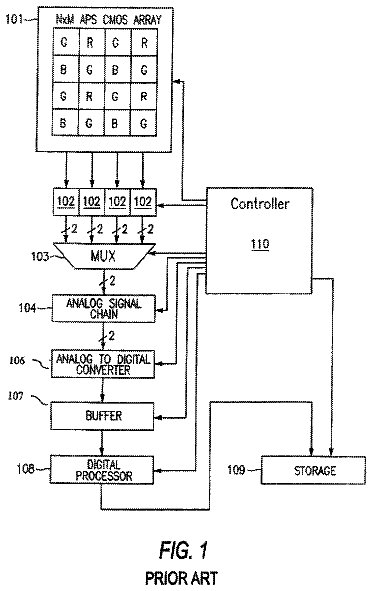
A solid-state image pickup device includes a light receiving section where M.times.N pixel units P.sub.1,1 to P.sub.M,N each including a photodiode and a charge accumulating section are two-dimensionally arrayed in M rows and N columns, a row selecting section that causes each pixel unit P.sub.m,n in a light receiving section to accumulate charge generated in its photodiode during a given period in its charge accumulating section, and to output data corresponding to an amount of the charge accumulated in each pixel unit P.sub.m,n in every row, and a readout section for which the data output from each pixel unit P.sub.m,n in the light receiving section is input and from which data corresponding to an amount of charge generated in the photodiode of each pixel unit P.sub.m,n is output. Also, in some cases, the solid-state image pickup device further includes an AD conversion section that analog/digital-converts the data output from the readout section to output a digital value.
Such a solid-state image pickup device is capable of detecting an intensity of light reaching each pixel unit P.sub.m,n in its light receiving section, to perform image pickup. Further, in recent years, not only image pickup, but an attempt has been made to perform optical communication by using such a solid-state image pickup device. For example, a solid-state image pickup device of the invention disclosed in Patent Literature 1 has a plurality of means for reading out data from each pixel unit, and is capable of performing image pickup by reading out data by every pixel unit with the first readout means among those. Further, the solid-state image pickup device adds current signals generated from photodiodes of specific one pixel unit, or two or more pixel units to output the signal with the second readout means, so that the solid-state image pickup device is capable of receiving an optical signal.
Citation list
Patent Literature
Patent Literature 1: Japanese Patent No. 3995959
Summary of invention
Technical Problem
It is necessary that the solid-state image pickup device of the invention disclosed in Patent Literature 1 include a storage section that stores data that is read out by any of the readout means, and a large number of switches for switching among output routes in order to read out data by specific readout means according to the stored content for every pixel unit. Therefore, the solid-state image pickup device of the invention disclosed in Patent Literature 1 has a larger region area per pixel unit and a smaller aperture ratio that is a ratio of an entire region area of the photodiode to a region area of the light receiving section in comparison with a conventional solid-state image pickup device.
It is necessary that the solid-state image pickup device of the invention disclosed in Patent Literature 1 include second signal readout means of a number which is the same as the number of the assumed optical signal receiving regions when it is assumed that there is a plurality of optical signal receiving regions in the light receiving section. Therefore, with this, the solid-state image pickup device of the invention disclosed in Patent Literature 1 has a larger region area per pixel unit and a smaller aperture ratio in comparison with a conventional solid-state image pickup device.
Moreover, in a case where the solid-state image pickup device of the invention disclosed in Patent Literature 1 includes K second signal readout means, when there are optical signal receiving regions of a number greater than K in the light receiving section, the solid-state image pickup device is incapable of receiving an optical signal reaching any of the optical signal receiving regions.
The present invention has been achieved in order to solve the above-described problems. An object of the present invention is to provide a solid-state image pickup device for optical communication which is capable of suppressing an increase in region area per pixel unit and a reduction in aperture ratio, and is capable of flexibly responding to a variation in the number of optical signal receiving regions in its light receiving section.
Solution to Problem
A solid-state image pickup device according to the present invention includes
a light receiving section where M.times.N pixel units P.sub.1,1 to P.sub.M,N each including a photodiode that generates charge of an amount according to an incident light amount, a charge accumulating section in which the charge is accumulated, a first switch for outputting data corresponding to an accumulated charge amount in the charge accumulating section, and a second switch for outputting data corresponding to the accumulated charge amount in the charge accumulating section are two-dimensionally arrayed in M rows and N columns,
a first row selecting section which selects any m1-th row in the light receiving section, and causes each pixel unit P.sub.m1,n of the row to accumulate the charge generated in the photodiode in the charge accumulating section, and to output data corresponding to the accumulated charge amount in the charge accumulating section to a readout signal line L1.sub.n by closing the first switch,
a second row selecting section which selects any m2-th row in the light receiving section, and causes each pixel unit P.sub.m2,n of the row to accumulate the charge generated in the photodiode in the charge accumulating section, and to output data corresponding to the accumulated charge amount in the charge accumulating section to a readout signal line L2.sub.n by closing the second switch,
a first readout section which is connected to N readout signal lines L1.sub.1 to L1.sub.N, for which data output from each pixel unit P.sub.m1,n of the m1-th row in the light receiving section selected by the first row selecting section to the readout signal line L1.sub.n is input, and from which data corresponding to an amount of the charge generated in the photodiode of each pixel unit P.sub.m1,n of the m1-th row is output, and
a second readout section which is connected to N readout signal lines L2.sub.1 to L2.sub.N, for which data output from each pixel unit P.sub.m2,n of the m2-th row in the light receiving section selected by the second row selecting section to the readout signal line L2.sub.n is input, and from which data corresponding to an amount of the charge generated in the photodiode of each pixel unit P.sub.m2,n of the m2-th row is output. Moreover, in the solid-state image pickup device according to the present invention, the first row selecting section and the second row selecting section select rows different from each other in the light receiving section, and the first row selecting section and the first readout section, and the second row selecting section and the second readout section operate in parallel with each other (provided that M and N are each an integer not less than 2, m, m1, and m2 are each an integer not less than 1 and not more than M, and n is an integer not less than 1 and not more than N).
In the solid-state image pickup device according to the present invention, any m1-th row in the light receiving section is selected by the first row selecting section, and in each pixel unit P.sub.m1,n of the row, the charge generated in the photodiode is accumulated in the charge accumulating section, and the data corresponding to the accumulated charge amount in the charge accumulating section is output to the readout signal line L1.sub.n by closing the first switch. In the first readout section which is connected to each readout signal L1.sub.n, data output from each pixel unit P.sub.m1,n of the m1-th row in the light receiving section selected by the first row selecting section to the readout signal line L1.sub.n is input, and data corresponding to the amount of charge generated in the photodiode of each pixel unit P.sub.m1,n of the m1-th row is output.
On the other hand, any m2-th row in the light receiving section is selected by the second row selecting section, and in each pixel unit P.sub.m2,n of the row, the charge generated in the photodiode is accumulated in the charge accumulating section, the data corresponding to the accumulated charge amount in the charge accumulating section is output to a readout signal line L2.sub.n by closing the second switch. In the second readout section which is connected to each readout signal line L2.sub.n, data output from each pixel unit P.sub.m2,n of the m2-th row in the light receiving section selected by the second row selecting section to the readout signal line L2.sub.n is input, and data corresponding to the amount of charge generated in the photodiode of each pixel unit P.sub.m2,n of the m2-th row is output.
Rows different from each other in the light receiving section are selected by the first row selecting section and the second row selecting section. Then, the first row selecting section and the first readout section, and the second row selecting section and the second readout section operate in parallel with each other. Thereby, for example, image data by the first row selecting section and the first readout section is obtained, and communication data by the second row selecting section and the second readout section is obtained.
In the solid-state image pickup device according to the present invention, it is preferable that (a1) in the light receiving section, a control signal line for providing control signals giving instructions for discharge from each of a junction capacitance section of the photodiode and the charge accumulating section in each pixel unit P.sub.m,n and for charge accumulation by the charge accumulating section to each pixel unit P.sub.m,n, be provided to every row, and a switch or a tri-state buffer be provided to each terminal of each control signal line, (b1) the first row selecting section output the control signal to the control signal line via the switch or the tri-state buffer provided to a first terminal of the control signal line of the m1-th row, and (c1) the second row selecting section output the control signal to the control signal line via the switch or the tri-state buffer provided to a second terminal of the control signal line of the m2-th row.
In this case, it is preferable that (b2) the first row selecting section include M latch circuits, and when data held in an m1-th latch circuit among the M latch circuits is a significant value, the first row selecting section output the control signal to the control signal line via the switch or the tri-state buffer provided to the first terminal of the control signal line of the m1-th row, and (c2) the second row selecting section include M latch circuits, and when data held in an m2-th latch circuit among the M latch circuits is a significant value, the second row selecting section output the control signal to the control signal line via the switch or the tri-state buffer provided to the second terminal of the control signal line of the m2-th row.
Alternatively, in the solid-state image pickup device according to the present invention, it is preferable that (a3) in the light receiving section, a control signal line for providing control signals giving instructions for discharge from each of a junction capacitance section of the photodiode and the charge accumulating section in each pixel unit P.sub.m,n and for charge accumulation by the charge accumulating section to each pixel unit P.sub.m,n, be provided to every row, and an OR circuit be provided to one terminal of each control signal line, (b3) the first row selecting section output the control signal to the control signal line via the OR circuit provided to the one terminal of the control signal line of the m1-th row, and (c3) the second row selecting section output the control signal to the control signal line via the OR circuit provided to the one terminal of the control signal line of the m2-th row.
In this case, it is preferable that (b4) the first row selecting section include M latch circuits, and when data held in an m1-th latch circuit among the M latch circuits is a significant value, the first row selecting section output the control signal to the control signal line via the OR circuit provided to the one terminal of the control signal line of the m1-th row, and (c4) the second row selecting section include M latch circuits, and when data held in an m2-th latch circuit among the M latch circuits is a significant value, the second row selecting section output the control signal to the control signal line via the OR circuit provided to the one terminal of the control signal line of the m2-th row.
In the solid-state image pickup device according to the present invention, it is preferable that the M latch circuits of each of the first row selecting section and the second row selecting section be cascade-connected in order of the rows, to compose a shift register, and M-bit data be serial-input to a latch circuit at the first stage in the shift register, to cause each latch circuit to hold data.
In the solid-state image pickup device according to the present invention, it is preferable that the first row selecting section sequentially output the control signals at a constant time interval to a plurality of rows corresponding to latch circuits with holding data of significant values among the M latch circuits included in the first row selecting section, and the second row selecting section sequentially output the control signals at a constant time interval to a plurality of rows corresponding to latch circuits with holding data of significant values among the M latch circuits included in the second row selecting section.
Advantageous Effects of Invention
The solid-state image pickup device according to the present invention is capable of suppressing an increase in region area per pixel unit and a reduction in aperture ratio, and is capable of flexibly responding to a variation in the number of optical signal receiving regions in its light receiving section.
Brief description of drawings
FIG. 1 is a diagram showing a schematic configuration of a solid-state image pickup device 1 according to a first embodiment.
FIG. 2 is a diagram showing configurations of a first readout section 40 and a second readout section 50 of the solid-state image pickup device 1 according to the first embodiment.
FIG. 3 is a diagram showing circuit configurations of a pixel unit P.sub.m,n and a holding section 41.sub.n of the solid-state image pickup device 1 according to the first embodiment.
FIG. 4 is a diagram showing a circuit configuration of a difference arithmetic section 43 of the solid-state image pickup device 1 according to the first embodiment.
FIG. 5 is a diagram showing a configuration of a first row selecting section 20 of the solid-state image pickup device 1 according to the first embodiment.
FIG. 6 is a diagram showing a configuration of a control signal generating circuit 21.sub.m of the first row selecting section 20 of the solid-state image pickup device 1 according to the first embodiment.
FIG. 7 is a timing chart showing an example of the operation of the solid-state image pickup device 1 according to the first embodiment.
FIG. 8 is a timing chart showing another example of the operation of the solid-state image pickup device 1 according to the first embodiment.
FIG. 9 is a timing chart showing yet another example of the operation of the solid-state image pickup device 1 according to the first embodiment.
FIG. 10 is a diagram showing a schematic configuration of a solid-state image pickup device 2 according to a second embodiment.
FIG. 11 is a diagram showing configurations of a first row selecting section 20 and a second row selecting section 30 of the solid-state image pickup device 2 according to the second embodiment.
Description of embodiments
Hereinafter, embodiments of the present invention will be described in detail with reference to the accompanying drawings. Also, the same components will be denoted with the same reference numerals in the description of the drawings, and overlapping description will be omitted.
First Embodiment
FIG. 1 is a diagram showing a schematic configuration of a solid-state image pickup device 1 according to a first embodiment.
The solid-state image pickup device 1 shown in this figure includes a light receiving section 10, a first row selecting section 20, a second row selecting section 30, a first readout section 40, a second readout section 50, and a control section 60.
The light receiving section 10 includes M.times.N pixel units P.sub.1,1 to P.sub.M,N. The M.times.N pixel units P.sub.1,1 to P.sub.M,N have a common configuration, and these are two-dimensionally arrayed in M rows and N columns. Each pixel unit P.sub.m,n is located in the m-th row and the n-th column. Here, M and N are each an integer not less than 2, and m is an integer not less than 1 and not more than M, and n is an integer not less than 1 and not more than N.
Each pixel unit P.sub.m,n has a photodiode that generates charge of an amount according to an incident light amount and a charge accumulating section in which the charge is accumulated. Each pixel unit P.sub.m,n accumulates charge generated in its photodiode in its charge accumulating section on the basis of various control signals received via control signal lines from the first row selecting section 20 or the second row selecting section 30, and outputs data corresponding to the accumulated charge amount in the charge accumulating section to a readout signal line L1.sub.n or a readout signal line L2.sub.n.
The first row selecting section 20 selects any m1-th row in the light receiving section 10, and causes each pixel unit P.sub.m1,n of the row to accumulate the charge generated in the photodiode in the charge accumulating section, and to output data corresponding to the accumulated charge amount in the charge accumulating section to the readout signal line L1.sub.n.
The second row selecting section 30 selects any m2-th row in the light receiving section 10, and causes each pixel unit P.sub.m2,n of the row to accumulate the charge generated in the photodiode in the charge accumulating section, and to output data corresponding to the accumulated charge amount in the charge accumulating section to the readout signal line L2.sub.n.
Here, m1 and m2 are each an integer not less than 1 and not more than M. The number of rows selected by each of the first row selecting section 20 and the second row selecting section 30 is arbitrary. However, the output of data is sequentially carried out with respect to every single row. Meanwhile, the first row selecting section 20 and the second row selecting section 30 select rows different from each other in the light receiving section 10.
The first readout section 40 is connected to N readout signal lines L1.sub.1 to L1.sub.N, and data output from each pixel unit P.sub.m1,n of the m1-th row in the light receiving section 10 selected by the first row selecting section 20 to the readout signal line L1.sub.n is input thereto, and data corresponding to an amount of charge generated in its photodiode of each pixel unit P.sub.m1,n of the m1-th row is output therefrom.
The second readout section 50 is connected to N readout signal lines L2.sub.1 to L2.sub.N, data output from each pixel unit P.sub.m2,n of the m2-th row in the light receiving section 10 selected by the second row selecting section 30 to the readout signal line L2.sub.n is input thereto, and data corresponding to an amount of charge generated in its photodiode of each pixel unit P.sub.m2,n of the m2-th row is output therefrom.
The control section 60 controls respective operations of the first row selecting section 20, the second row selecting section 30, the first readout section 40, and the second readout section 50, to control the entire operation of the solid-state image pickup device 1. The first row selecting section 20 and the first readout section 40, the second row selecting section 30 and the second readout section 50 are capable of operating in parallel with each other under the control of the control section 60.
FIG. 2 is a diagram showing configurations of the first readout section 40 and the second readout section 50 of the solid-state image pickup device 1 according to the first embodiment. In this figure, the pixel unit P.sub.m,n of the m-th row and the n-th column is shown as a representative of the M.times.N pixel units P.sub.1,1 to P.sub.M,N in the light receiving section 10. Further, constitutional elements relating to the pixel unit P.sub.m,n are shown in each of the first readout section 40 and the second readout section 50.
The first readout section 40 includes N holding sections 41.sub.1 to 41.sub.N, a first column selecting section 42, and a difference arithmetic section 43. The N holding sections 41.sub.1 to 41.sub.N have a common configuration. Each holding section 41.sub.n is connected to M pixel units P.sub.1,n to P.sub.M,n of the n-th column in the light receiving section 10 via the readout signal line L1.sub.n, and allows data output from the pixel unit P.sub.m1,n of the m1-th row selected by the first row selecting section 20 to the readout signal line L1.sub.n to be input thereto, to hold the data, and is capable of outputting the held data. Each holding section 41.sub.n preferably allows data of signal components superimposed with noise components to be input thereto, to hold the data, and for allowing data of only noise components to be input thereto, to hold the data.
The N holding sections 41.sub.1 to 41.sub.N are capable of sampling data at a same timing on the basis of various control signals received from the first column selecting section 42, to hold the sampled data, and sequentially output the held data. The difference arithmetic section 43 allows the data sequentially output from the respective N holding sections 41.sub.1 to 41.sub.N to be input thereto, and subtracts the data of only noise components from the data of signal components superimposed with noise components, to output data corresponding to the signal components. The difference arithmetic section 43 may output the data corresponding to the signal components as analog data, or may have an AD conversion function to output digital data. In this way, the first readout section 40 is capable of outputting data corresponding to an amount of charge generated in the photodiode of each pixel unit P.sub.m1,n of the m1-th row.
The second readout section 50 includes N holding sections 51.sub.1 to 51.sub.N, a second column selecting section 52, and a difference arithmetic section 53. The N holding sections 51.sub.1 to 51.sub.N have a common configuration. Each holding section 51.sub.n is connected to M pixel units P.sub.1,n to P.sub.M,n of the n-th column in the light receiving section 10 via the readout signal line L2.sub.n, and allows data output from the pixel unit P.sub.m2,n of the m2-th row selected by the second row selecting section 20 to the readout signal line L2.sub.n to be input thereto, to hold the data, and is capable of outputting the held data. Each holding section 51.sub.n preferably allows data of signal components superimposed with noise components to be input thereto, to hold the data, and for allowing data of only noise components to be input thereto, to hold the data.
The N holding sections 51.sub.1 to 51.sub.N are capable of sampling data at a same timing on the basis of various control signals received from the second column selecting section 52, to hold the sampled data, and sequentially output the held data. The difference arithmetic section 53 allows the data sequentially output from the respective N holding sections 51.sub.1 to 51.sub.N to be input thereto, and subtracts the data of only noise components from the data of signal components superimposed with noise components, to output data corresponding to the signal components. The difference arithmetic section 53 may output the data corresponding to the signal components as analog data, or may have an AD conversion function to output digital data. In this way, the second readout section 50 is capable of outputting data corresponding to an amount of charge generated in its photodiode of each pixel unit P.sub.m2,n of the m2-th row.
FIG. 3 is a diagram showing circuit configurations of the pixel unit P.sub.m,n and the holding section 41.sub.n of the solid-state image pickup device 1 according to the first embodiment. In this figure as well, the pixel unit P.sub.m,n of the m-th row and the n-th column is shown as a representative of the M.times.N pixel units P.sub.1,1 to P.sub.M,N in the light receiving section 10. Further, the holding section 41.sub.n relating to the pixel unit P.sub.m,n is shown in the first readout section 40. In addition, the configuration of the holding section 51.sub.n is the same as the configuration of the holding section 41.sub.n.
Each pixel unit P.sub.m,n is of the APS (Active Pixel Sensor) type, that includes a photodiode PD and 6 MOS transistors T1, T2, T3, T4.sub.1, T4.sub.2, and T5. As shown in this figure, the transistor T1, the transistor T2, and the photodiode PD are sequentially connected in series, and a reference voltage is input to the drain terminal of the transistor T1, and the anode terminal of the photodiode PD is grounded. The connection point between the transistor T1 and the transistor T2 is connected to the gate terminal of the transistor T3 via the transistor T5.
A reference voltage is input to the drain terminal of the transistor T3. The source terminal of the transistor T3 is connected to the respective drain terminals of the transistors T4.sub.1 and T4.sub.2. The source terminal of the transistor T4.sub.1 of each pixel unit P.sub.m,n is connected to the readout signal line L1.sub.n. The source terminal of the transistor T4.sub.2 of each pixel unit P.sub.m,n is connected to the readout signal line L2.sub.n. A constant current source is connected to the readout signal line L1.sub.n and the readout signal line L2.sub.n, respectively.
The gate terminal of the transistor T2 for transfer in each pixel unit P.sub.m,n is connected to a control signal line LT.sub.m, and a Trans1(m) signal output from the first row selecting section 20 or a Trans2(m) signal output from the second row selecting section 30 is input as a Trans(m) signal on the control signal line LT.sub.m. The gate terminal of the transistor T1 for reset in each pixel unit P.sub.m,n is connected to a control signal line LR.sub.m, and a Reset1(m) signal output from the first row selecting section 20 or a Reset2(m) signal output from the second row selecting section 30 is input as a Reset(m) signal on the control signal line. The gate terminal of the transistor T5 for hold in each pixel unit P.sub.m,n is connected to a control signal line LH.sub.m, and a Hold1(m) signal output from the first row selecting section 20 or a Hold2(m) signal output from the second row selecting section 30 is input as a Hold(m) signal on the control signal line.
The gate terminal of the transistor T4.sub.1 for output selection in each pixel unit P.sub.m,n is connected to a control signal line LA1.sub.m, and an Address1(m) signal output from the first row selecting section 20 is input thereto. The gate terminal of the transistor T4.sub.2 for output selection in each pixel unit P.sub.m,n is connected to a control signal line LA2.sub.m, and an Address2(m) signal output from the second row selecting section 30 is input thereto. These control signals (a Reset(m) signal, a Trans(m) signal, a Hold(m) signal, an Address1(m) signal, and an Address2(m) signal) are input in common to the N pixel units P.sub.m,1 to P.sub.m,N of the m-th row.
The control signal line LT.sub.m, the control signal line LR.sub.m, and the control signal line LH.sub.m are provided to every row, and the control signals (a Reset(m) signal, a Trans(m) signal, a Hold(m) signal) giving instructions for discharge from each of the junction capacitance section of the photodiode PD in each pixel unit P.sub.m,n of the m-th row and the charge accumulating section, and for charge accumulation by the charge accumulating section are transmitted therethrough. The first terminals of these control signal lines are connected to the first row selecting section 20 via switches. Further, the second terminals of these control signal lines are connected to the second row selecting section 30 via switches. The two switches provided to the both terminals of each of these control signal lines do not close at the same time, and at least one of these is always open. In addition, tri-state buffers may be used in place of these switches. In this case, the two tri-state buffers provided to the both terminals of each of these control signal lines are not brought into a conduction state at the same time, and at least one of these is always in a high-impedance state.
The control signal line LA1.sub.m and the control signal line LA2.sub.m are provided to every row, and the control signals (an Address1(m) signal, an Address2(m) signal) for giving instructions for data output to the readout signal line L1.sub.n or the readout signal line L2.sub.n in each pixel unit P.sub.m,n of the m-th row are transmitted therethrough. Each control signal line LA1.sub.m is connected to the first row selecting section 20. Each control signal line LA2.sub.m is connected to the second row selecting section 30. The Address1(m) signal and the Address2(m) signal are not raised to a high level simultaneously, and the transistor T4.sub.1 and the transistor T4.sub.2 do not move into an on-state simultaneously.
When the Reset(m) signal, the Trans(m) signal, and the Hold(m) signal are at a high level, the junction capacitance section of the photodiode PD is discharged, and further, a diffusion region (the charge accumulating section) connected to the gate terminal of the transistor T3 is discharged. When the Trans(m) signal is at a low level, the charge generated in the photodiode PD is accumulated in the junction capacitance section. When the Reset(m) signal is at a low level and the Trans(m) signal and the Hold(m) signal are at a high level, the charge accumulated in the junction capacitance section of the photodiode PD is transferred to the diffusion region (the charge accumulating section) connected to the gate terminal of the transistor T3 to be accumulated therein.
When the Address1(m) signal is at a high level, data (data of signal components superimposed with noise components) corresponding to an amount of the charge accumulated in the diffusion region (the charge accumulating section) connected to the gate terminal of the transistor T3 is output to the readout signal line L1.sub.n via the transistor T4.sub.1, to be input to the holding section 41.sub.n of the first readout section 40. That is, the transistor T4.sub.1 operates as a first switch for outputting data corresponding to an accumulated charge amount in the charge accumulating section to the readout signal line L1.sub.n. In addition, when the charge accumulating section is in a state of discharge, data of only noise components is output to the readout signal line L1.sub.n via the transistor T4.sub.1.
When the Address2(m) signal is at a high level, data (data of signal components superimposed with noise components) corresponding to an amount of the charge accumulated in the diffusion region (the charge accumulating section) connected to the gate terminal of the transistor T3 is output to the readout signal line L2.sub.n via the transistor T4.sub.2, to be input to the holding section 51.sub.n of the second readout section 50. That is, the transistor T4.sub.2 operates as a second switch for outputting data corresponding to an accumulated charge amount in the charge accumulating section to the readout signal line L2.sub.n. In addition, when the charge accumulating section is in a state of discharge, data of only noise components is output to the readout signal line L2.sub.n via the transistor T4.sub.2.
Each holding section 41.sub.n includes two capacitive elements C.sub.1 and C.sub.2, and four switches SW.sub.11, SW.sub.12, SW.sub.21, and SW.sub.22. In this holding section 41.sub.n, the switch SW.sub.11 and the switch SW.sub.12 are connected in series to be provided between the readout signal line L1.sub.n and a wiring Hline_s1, and one terminal of the capacitive element C.sub.1 is connected to the connection point between the switch SW.sub.11 and the switch SW.sub.12, and the other terminal of the capacitive element C.sub.1 is grounded. Further, the switch SW.sub.21 and the switch SW.sub.22 are connected in series to be provided between the readout signal line L1.sub.n and a wiring Hline_n1, and one terminal of the capacitive element C.sub.2 is connected to the connection point between the switch SW.sub.21 and the switch SW.sub.22, and the other terminal of the capacitive element C.sub.2 is grounded.
In this holding section 41.sub.n, the switch SW.sub.11 opens and closes according to a level of a set_s1 signal supplied from the first column selecting section 42. The switch SW.sub.21 opens and closes according to a level of a set_n1 signal supplied from the first column selecting section 42. The set_s1 signal and the set_n1 signal are input in common to the N holding sections 41.sub.1 to 41.sub.N. The switches SW.sub.12 and SW.sub.22 open and close according to a level of an hshift1(n) signal supplied from the first column selecting section 42.
In this holding section 41.sub.n, when the set_n1 signal is shifted from a high level to a low level and the switch SW.sub.21 opens, the noise components output from the pixel unit P.sub.m,n to the readout signal line L1.sub.n are thereafter held as a voltage value out_n1(n) by the capacitive element C.sub.2. When the set_s1 signal is shifted from a high level to a low level and the switch SW.sub.11 opens, the signal components superimposed with noise components output from the pixel unit P.sub.m,n to the readout signal line L1.sub.n are thereafter held as a voltage value out_s1(n) by the capacitive element C.sub.1. Then, when the hshift1(n) signal is raised to a high level, the switch SW.sub.12 is closed to output the voltage value out_s1(n) held by the capacitive element C.sub.1 to the wiring Hline_s1, and the switch SW.sub.22 is closed to output the voltage value out_n1(n) held by the capacitive element C.sub.2 to the wiring Hlinen1. A difference between these voltage value outs 1(n) and voltage value out_n1(n) represents a voltage value corresponding to an amount of charge generated in its photodiode PD of the pixel unit P.sub.m,n.
FIG. 4 is a diagram showing a circuit configuration of the difference arithmetic section 43 of the solid-state image pickup device 1 according to the first embodiment. In addition, the configuration of the difference arithmetic section 53 is the same as the configuration of the difference arithmetic section 43. As shown in this figure, the difference arithmetic section 43 includes amplifiers A.sub.1 to A.sub.3, switches SW.sub.1 and SW.sub.2, and resistors R.sub.1 to R.sub.4. The inverting input terminal of the amplifier A.sub.3 is connected to the output terminal of the buffer amplifier A.sub.1 via the resistor R.sub.1, and is connected to its own output terminal via the resistor R.sub.3. The non-inverting input terminal of the amplifier A.sub.3 is connected to the output terminal of the buffer amplifier A.sub.2 via the resistor R.sub.2, and is connected to a grounding potential via the resistor R.sub.4. The input terminal of the buffer amplifier A.sub.1 is connected to the N holding sections 41.sub.1 to 41.sub.N via the wiring Hline_s1, and is connected to a grounding potential via the switch SW.sub.1. The input terminal of the buffer amplifier A.sub.2 is connected to the N holding sections 41.sub.1 to 41.sub.N via the wiring Hline_n1, and is connected to a grounding potential via the switch SW.sub.2.
The switches SW.sub.1 and SW.sub.2 in the difference arithmetic section 43 are controlled by an hreset1 signal supplied from the first column selecting section 42 to carry out an opening and closing operation. When the switch SW.sub.1 is closed, the voltage value input to the input terminal of the buffer amplifier A.sub.1 is reset. When the switch SW.sub.2 is closed, the voltage value input to the input terminal of the buffer amplifier A.sub.2 is reset. When the switches SW.sub.1 and SW.sub.2 are open, the voltage values out_s1(n) and out_n1(n) output to the wirings Hline_s1 and Hline_n1 from any holding section 41.sub.n among the N holding sections 41.sub.1 to 41.sub.N are input to the input terminals of the buffer amplifiers A.sub.1 and A.sub.2. Assuming that the respective gains of the buffer amplifiers A.sub.1 and A.sub.2 are 1, and the respective resistance values of the four resistors R.sub.1 to R.sub.4 are equal to one another, a voltage value output from the output terminal of the difference arithmetic section 43 represents a difference between the voltage values respectively input via the wiring Hline_s1 and the wiring Hline_n1, that is the value from which noise components are eliminated.
FIG. 5 is a diagram showing a configuration of the first row selecting section 20 of the solid-state image pickup device 1 according to the first embodiment. As shown in this figure, the first row selecting section 20 includes M control signal generating circuits 21.sub.1 to 21.sub.M composing a first shift register, and M latch circuits 22.sub.1 to 22.sub.M composing a second shift register.
The M control signal generating circuits 21.sub.1 to 21.sub.M have a common configuration, and these are cascade-connected sequentially. That is, an input terminal I of each control signal generating circuit 21.sub.m is connected to an output terminal O of a control signal generating circuit 21.sub.m-1 at the previous stage (here, m is an integer not less than 2 and not more than M). A vshift1
signal at a high level at a timing of instruction from a clock VCLK1 and at a low level thereafter is input to the input terminal I of the control signal generating circuit 21.sub.1 at the first stage.
Each control signal generating circuit 21.sub.m operates in synchronization with the clock VCLK1, and when a basic control signal 1 is input, and data row_sel1_data[m] held by a corresponding latch circuit 22.sub.m is at a high level, the control signal generating circuit 21.sub.m outputs the Reset1(m) signal, the Trans1(m) signal, the Hold1(m) signal, and the Address1(m) signal. When the data row_sel1_data[m] held by a corresponding latch circuit 22.sub.m is at a low level, each control signal generating circuit 21.sub.m does not output the Reset1(m) signal, the Trans1(m) signal, the Hold1(m) signal, and the Address1(m) signal.
The M latch circuits 22.sub.1 to 22.sub.M are each a D flip-flop, and these are sequentially cascade-connected. That is, an input terminal D of each latch circuit 22.sub.m is connected to an output terminal Q of a latch circuit 22.sub.m-1 at the previous stage (here, m is an integer not less than 2 and not more than M). M-bit data row_sel1_data[M:1] are serial-input to the input terminal D of the latch circuit 22.sub.1 at the first stage. Each latch circuit 22.sub.m operates in synchronization with a clock row_sel1_clk, to be capable of holding the data row_sel1_data[m].
Each latch circuit 22.sub.m provides the holding data row_sel1_data[m] to a corresponding control signal generating circuit 21.sub.m. Further, each latch circuit 22.sub.m provides the holding data row_sel1_data[m] to the switches provided to the respective first terminals of the control signal line LT.sub.m, the control signal line LR.sub.m, and the control signal line LH.sub.m, to control opening and closing operations of these switches. When the data row_sel1_data[m] is at a high level, these switches are closed.
The description continues in the full USPTO document.
 Lapsed, fee not paid4 drawings