Lapsed, fee not paid29 drawings
Vehicles & Drones · US 8,764,869 B2
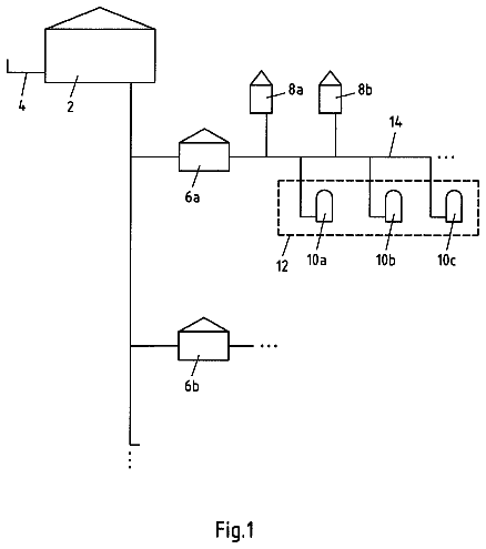
Gas cleaning separator
The present invention relates to a separator and more specifically, but not exclusively, to a centrifugal separator for the cleaning of a gaseous fluid.
US 8,766,566 B2 · Assignee: Nippon Soken, Inc. · Inventors: Baba; Hiroyasu et al.
Sheet 1 of 10 from the published document. All sheets in the USPTO PDF
A battery temperature rise causing system has a converting unit for converting voltage of electric power held in one of a rechargeable battery and an accumulator and applies the converted voltage to the other one, and a control unit controlling the converting unit to alternately perform first transfer of electric power from the battery to the accumulator and second transfer of electric power from the accumulator to the battery while changing the first transfer for the second transfer each time the battery voltage reaches a lower limit and changing the second transfer for the first transfer each time the battery voltage reaches an upper limit, and to increase temperature of the battery due to heat generated by electric current flowing through the battery during the electric power transfer.
A voltage converting device mounted on a hybrid vehicle or an electric car rapidly increases the temperature of a rechargeable secondary battery. This device is, for example, disclosed in Published Japanese Patent First Publication No. JP2005-312160. In this device of the Publication, a temperature sensor detects a temperature of a direct-current (dc) power source. When the source temperature is lower than a reference value, the device performs a temperature increasing control for the source. More specifically, a control unit controls a boost converter to repeatedly perform a voltage increasing operation and a voltage dropping operation. In the voltage increasing operation, electric power is sent from the power source to a capacitor through resistors of the power source. In the voltage dropping operation, electric power is sent from the capacitor to the power source through the resistors
8 of 10 drawing sheets so far from the published document, cropped to the drawing. Every sheet is in the USPTO PDF.
What the patent claimed, word for word. All of it is now free to use.
This application is based upon and claims the benefit of priority of the prior Japanese Patent Application 2010-283170 filed on Dec. 20, 2010 and the prior Japanese Patent Application 2011-1183864 filed on May 27, 2011, so that the contents of which are incorporated herein by reference.
The present invention relates generally to a system for rapidly causing a temperature rise in a battery of a hybrid vehicle or an electric car, and more particularly to the system for rapidly causing a temperature rise in the battery while assuring the safety of the battery and the system for rapidly causing a temperature rise in the battery while keeping the voltage of electric power, applied from the battery to an electric motor, at a value required to drive the vehicle or car at a desired speed.
A voltage converting device mounted on a hybrid vehicle or an electric car rapidly increases the temperature of a rechargeable secondary battery. This device is, for example, disclosed in Published Japanese Patent First Publication No. JP2005-312160.
In this device of the Publication, a temperature sensor detects a temperature of a direct-current (dc) power source. When the source temperature is lower than a reference value, the device performs a temperature increasing control for the source. More specifically, a control unit controls a boost converter to repeatedly perform a voltage increasing operation and a voltage dropping operation. In the voltage increasing operation, electric power is sent from the power source to a capacitor through resistors of the power source. In the voltage dropping operation, electric power is sent from the capacitor to the power source through the resistors. Therefore, the temperature of the source heated by the resistors is increased. When the source temperature exceeds the reference value, the temperature increasing control is stopped, and the control unit controls the boost converter to perform a normal operation. In this normal operation, the voltage increasing operation, the voltage dropping operation or repetition of the increasing and dropping operations is performed. The voltage of the electric power accumulated in the capacitor is applied to the motor as a driving voltage, required to drive the motor at a desired speed.
However, when a rechargeable battery such as a lithium-ion rechargeable battery or the like is used as the dc power source, the internal resistance of the battery is increased during a low temperature period of time in which the atmospheric temperature is, for example, lower than the freezing point. Therefore, when large electric current flows through the battery at a low frequency during the voltage rising and dropping operations repeatedly performed, a change in the voltage of the battery is increased. In this case, the battery voltage sometimes exceeds its upper limit or becomes lower than its lower limit. Therefore, it is difficult to rapidly increase the battery temperature while assuring the safety of the battery (first drawback of the voltage converting device).
For example, in the case of the lithium-ion rechargeable battery, when the battery is overcharged so as to exceed the upper limit of the battery voltage, electrolytic solution of the battery is sometimes oxidized near the positive electrode of the battery, the crystal structure of the positive electrode is sometimes broken or damaged, and lithium is sometimes deposited on the negative electrode of the battery. In contrast, when the battery is over-discharged so as to become lower than the lower limit of the battery voltage, copper composing the negative electrode is sometimes dissolved away by the electrolyte. In the same manner, any rechargeable battery other than the lithium-ion rechargeable battery is also damaged when being overcharged or over-discharged.
Further, the driving voltage applied from the capacitor to the motor is changeable. When the engine of the vehicle or car starts driving or when the motor is operated to run the vehicle or car at a high speed, this driving voltage is sometimes increased to the maximum value such as 650 V. In this situation, when the temperature increasing control is performed, the voltage of the capacitor is considerably decreased during the voltage drop operation to be lower than the required driving voltage, and a voltage lower than the driving voltage, which is insufficient to drive the motor, is undesirably applied to the motor. Therefore, it is difficult to generate a driving torque, required to start the running of the vehicle or car or to run the vehicle or car at a desired speed, in the motor (second drawback of the voltage converting device).
Hence it is desired to provide a system for rapidly causing a temperature rise in a battery while assuring the safety of the battery.
It is also desired to provide a system for rapidly causing a temperature rise in a battery while applying a voltage, required to drive an electric motor, to the motor.
According to a first aspect of this disclosure, the first object is achieved by the provision of a battery temperature rise causing system comprising a rechargeable battery, an accumulator, a voltage converting unit, and a control unit. The rechargeable battery holds electric power. The accumulator accumulates the electric power received from the battery. The voltage converting unit performs voltage conversion of the electric power between the battery and the accumulator. The control unit receives a battery temperature of the battery and controls the converting unit, when the received battery temperature is lower than a reference value, to increase the battery temperature while alternately transferring electric power from the accumulator to the battery and from the battery to the accumulator. Further, the control unit receives a battery voltage of the battery and controls the converting unit to change a transfer direction of the electric power between the battery and the capacitor each time the received battery voltage reaches a battery upper limit or a battery lower limit.
With this structure of the system, the control unit controls the converting unit to change the transfer of the electric power from the accumulator to the battery to the transfer of the electric power from the battery to the accumulator each time the battery voltage reaches the battery upper limit and to change the transfer of the electric power from the battery to the accumulator to the transfer of the electric power from the accumulator to the battery each time the battery voltage reaches the battery lower limit. Therefore, the control unit controls the converting unit to change the battery voltage within the range from the battery upper limit to the battery lower limit.
Accordingly, the system can prevent the battery from being overcharged or over-discharged so as to prevent the battery from being damaged or broken, and can assure the safety of the battery.
Further, because the control unit controls the converting unit to alternately transfer the electric power from the accumulator to the battery and transfer the electric power from the battery to the accumulator, electric current flows through the battery so as to generate heat in the battery. Accordingly, when the battery temperature is lower than the reference value, the system can rapidly cause a temperature rise in the battery.
According to a second aspect of this disclosure, the first object is achieved by the provision of a battery temperature rise causing system comprising the rechargeable battery, the accumulator, the voltage converting unit, and a control unit that receives a battery temperature of the battery and controls the converting unit, when the received battery temperature is lower than a reference value, to increase the battery temperature while alternately transferring electric power from the accumulator to the battery and from the battery to the accumulator. Further, the control unit stores in advance data indicating a relation between frequency in the transfer of the electric power and calorific power, generated in the battery due to the alternated transfer of the electric power, for each of levels of the battery temperature on condition that a battery voltage of the battery is lower than a battery upper limit and is higher than a battery lower limit, determines an optimum frequency at which the calorific power corresponding to the received battery temperature is maximized, and controls the converting unit to change a transfer direction of the electric power between the battery and the capacitor at the optimum frequency.
With this structure of the system, the control unit controls the converting unit to alternately transfer electric power from the battery to the accumulator and transfer electric power from the accumulator to the battery while changing the battery voltage within the range from the battery upper limit to the battery lower limit. Accordingly, the system can prevent the battery from being overcharged or over-discharged so as to prevent the battery from being damaged or broken, and can assure the safety of the battery.
Further, the control unit determines the optimum frequency, at which the calorific power is maximized, from the relation between the frequency and the calorific power corresponding to the received battery temperature and controls the converting unit to change the transfer direction of the electric power at the optimum frequency. Accordingly, when the battery temperature is lower than the reference value, the system can rapidly cause a temperature rise in the battery.
According to a third aspect of this disclosure, the first object is achieved by the provision of a battery temperature rise causing system comprising the rechargeable battery, the accumulator, the voltage converting unit, and a control unit that receives a battery temperature of the battery and controls the converting unit, when the received battery temperature is lower than a reference value, to increase the battery temperature while alternately transferring electric power from the accumulator to the battery and from the battery to the accumulator. Further, the control unit stores in advance data indicating a relation between frequency in the transfer of the electric power and battery current flowing through the battery, for each of levels of battery temperature on condition that a battery voltage of the battery is lower than a battery upper limit and is higher than a battery lower limit, determines an optimum frequency at which calorific power generated in the battery due to the alternated transfer of the electric power is maximized, by using the relation corresponding to the level of the received battery temperature, and controls the converting unit to change a transfer direction of the electric power between the battery and the capacitor at the optimum frequency.
With this structure of the system, the control unit controls the converting unit to alternately transfer electric power from the battery to the accumulator and transfer electric power from the accumulator to the battery while changing the battery voltage within the range from the battery upper limit to the battery lower limit. Accordingly, the system can prevent the battery from being overcharged or over-discharged so as to prevent the battery from being damaged or broken, and can assure the safety of the battery.
Further, the control unit knows in advance an impedance of the battery depending on the battery temperature and the frequency, and can determine the calorific power from the impedance and the battery current. Therefore, the control unit determines the optimum frequency, at which the calorific power is maximized, from the relation between the frequency and the received battery temperature and controls the converting unit to change the transfer direction of the electric power at the optimum frequency. Accordingly, when the battery temperature is lower than the reference value, the system can rapidly cause a temperature rise in the battery.
According to a fourth aspect of this disclosure, the second object is achieved by the provision of a battery temperature rise causing system comprising a rechargeable battery, an accumulator, a voltage converting unit, an inverter and a control unit. The rechargeable battery holds electric power. The accumulator accumulates the electric power received from the battery or accumulates electric power regenerated in an electric motor. The voltage converting unit performs voltage conversion of the electric power between the battery and the accumulator. The inverter converts an accumulated power voltage of the electric power accumulated in the accumulator into an alternating current voltage and applies the alternating current voltage to the electric motor to drive the electric motor during running of a vehicle. The control unit receives a battery temperature of the battery and controls the converting unit, when the received battery temperature is lower than a reference value, to increase the battery temperature while alternately transferring electric power from the accumulator to the battery and transferring electric power from the battery to the accumulator. Further, the control unit determines a driving voltage, required to drive the electric motor, according to a running condition of the vehicle, receives the accumulated power voltage of the accumulator and a battery voltage of the battery, and controls the converting unit according to the driving voltage, the accumulated power voltage and the battery voltage to alternately perform the transfers of the electric power.
With this structure of the system, the control unit controls the converting unit to alternately transfer electric power from the accumulator to the battery and transfer electric power from the battery to the accumulator. Therefore, an electric current flows through the battery so as to generate heat in the battery. Accordingly, the system can rapidly cause a temperature rise in the battery.
Further, the control of the control unit is performed according to the driving voltage. Therefore, the system can reliably apply the driving voltage, required to drive the motor, to the motor.
Accordingly, the system can rapidly causing a temperature rise in the battery while applying the driving voltage, required to drive the motor, to the motor.
Preferably, the control unit controls the converting unit to alternately perform the transfers of the electric power when the determined driving voltage is lower than a predetermined threshold value being equal to a maximum of a voltage required to drive the electric motor while the accumulated power voltage is higher than the determined driving voltage.
With this structure of the system, the driving voltage is changeable and depends on the running condition of the vehicle. When the vehicle starts running or is now running at a high speed, the motor requires the maximum driving voltage (e.g., 650V), and the driving voltage reaches the predetermined threshold value. Further, to reliably apply the driving voltage to the motor during a temperature increasing control performed under control of the control unit, the accumulated power voltage should be higher than the determined driving voltage. In this situation, when the determined driving voltage is increased to the predetermined threshold value, the accumulated power voltage is increased to a high value higher than the predetermined threshold value during the temperature increasing control, and the accumulator is sometimes damaged due to the high voltage of the electric power accumulated in the accumulator.
Because the control unit controls the converting unit to alternately perform the transfers of the electric power when the determined driving voltage is lower than the predetermined threshold value, the system can prevent the accumulator from being damaged.
FIG. 1 is a structure view of an electric current consumer driving apparatus with a battery temperature rise causing system according to the first embodiment of the present invention;
FIG. 2 is a timing chart of voltage, current and temperature in the system shown in FIG. 1;
FIG. 3 is a flow chart of a temperature increasing control performed in the system according to the first embodiment;
FIG. 4 is a view showing the relation between frequency and impedance of a battery according to the second embodiment of the present invention;
FIG. 5 is a view showing the relation between frequency and battery current according to the second embodiment;
FIG. 6 is a view showing the relation between frequency and calorific power according to the second embodiment;
FIG. 7 is a flow chart of a temperature increasing control performed in the system according to the second embodiment;
FIG. 8 is a view showing a change in a battery temperature in each of a constant optimum frequency and a changeable optimum frequency according to the second embodiment;
FIG. 9 is a structure view of an electric current consumer driving apparatus with a battery temperature rise causing system according to the third embodiment of the present invention;
FIG. 10 is a timing chart of voltage, current and temperature in the system shown in FIG. 9;
FIG. 11 is a flow chart of a temperature increasing control according to the third embodiment;
FIG. 12 shows a change of a capacitor voltage and a change of a battery current when no temperature increasing control is performed; and
FIG. 13 shows a change of a capacitor voltage and a change of a battery current when a temperature increasing control is performed according to the third embodiment.
Embodiments of the present invention will now be described with reference to the accompanying drawings, in which like reference numerals indicate like parts, members or elements throughout the specification unless otherwise indicated.
First Embodiment
FIG. 1 is a structure view of an electric current consumer driving apparatus with a battery temperature rise causing system according to the first embodiment. As shown in FIG. 1, an electric current consumer driving apparatus has a battery temperature rise causing system 10, an inverter 20, and an electric current consumer 30 such as an inverter or an electric motor.
The temperature rise causing system 10 can be used for an electric car such as a hybrid vehicle or a plug-in hybrid vehicle to rapidly warm or heat a rechargeable battery of the car. The system 10 has a rechargeable secondary battery 11 for holding electric power, an electric power accumulator 13 such as a capacitor for accumulating the electric power transferred from the battery 11, a voltage converting unit 12 for performing voltage conversion of the electric power between the battery 11 and the accumulator 13, a driving circuit 14 for outputting driving signals to the converting unit 12 and the inverter 20 to drive the converting unit 12 and the inverter 20, and a control unit 15 for controlling the circuit 14 to output the driving signals to the converting unit 12 and the inverter 20 in a normal operation and to output the driving signals to the converting unit 12 for the purpose of increasing a temperature Tb of the battery 11 in a temperature increasing control.
The battery 11 has a series of battery cells (not shown). As each cell, a lithium-ion rechargeable battery is used. The battery 11 is used as a power source for driving the current consumer 30. A battery temperature detector 16 is disposed near the battery 11 to detect the temperature of the battery 11. Data of the detected battery temperature Tb are sent to the control unit 15. A voltage detecting unit (not shown) detects a voltage Vb of the battery 11. A battery current detector 17 detects a battery current Ib flowing through the battery 11. Data of the detected battery current Ib and data of the detected battery voltage Vb are sent to the control unit 15.
The converting unit 12 acts as a boost converter for performing a voltage conversion between the battery 11 and the accumulator (hereinafter, called a capacitor) 13. Therefore, the unit 12 denotes a DC-DC (direct current to direct current) converter. The unit 12 has a reactive element 12a, a first switching element 12b (Qc1), a second switching element 12c (Qc2), a first diode 12d (D1), and a second diode 12e (D2). The reactive element 12a has an end connected with the positive electrode of the battery 11 and has the other end connected with a connection point of the switching elements 12b and 12c. A reactor current detector 18 detects a reactor current (or a conversion current) IL flowing through the element 12a, and outputs data of the current IL to the control unit 15.
Each of the switching elements 12b and 12c is formed of an insulated gate bipolar transistor (IGBT). The elements 12b and 12c are serially connected with each other between a power line Lp and a ground line Lg of the inverter 20. More specifically, the collector of the element 12b is connected with the power line Lp, and the emitter of the element 12b is connected with the collector of the element 12c. The ground line Lg is connected with the emitter of the element 12c and the negative electrode of the battery 11. The diode 12d is connected with the collector and the emitter of the element 12b such that a diode current flows from the emitter to the collector. The diode 12e is connected with the collector and the emitter of the element 12c such that a diode current flows from the emitter to the collector. Each of the diodes 12d and 12e acts as a free wheeling diode (FWD).
The capacitor 13 has ends, respectively, connected with the power line Lp and the ground line Lg. The capacitor 13 disposed on the input side of the inverter 20 smoothes a direct-current voltage applied from the converting unit 12 and applies the smoothed voltage to the inverter 20. A voltage detecting unit (not shown) detects the electric potential difference between the ends of the capacitor 13 as a capacitor voltage (or an accumulated power voltage) Vc and outputs the capacitor voltage Vc to the control unit 15.
The driving circuit 14 outputs driving signals to the switching elements 12b and 12c of the unit 12 and the inverter 20 according to instructions of the control unit 15 to drive the unit 12 and the inverter 20. The circuit 14 and the unit 15 may be integrally formed.
The control unit 15 receives an instruction, indicating a driving of the current consumer 30, from an electronic control unit (not shown) disposed on the outside of the driving apparatus. In response to this instruction, the control unit 15 controls the circuit 14 to drive the converting unit 12 and the inverter 20. In the electronic control unit, a microcomputer with a central processing unit (CPU), a read only memory (ROM), an electrically erasable and programmable ROM (EEPROM), a random access memory (RAM) and the like executes predetermined functions according to software programs stored in ROM and the like.
The control unit 15 has a function for causing a rise of the temperature Tb in the battery 11. More specifically, a reference value Tth is, for example, preset at the freezing point (i.e., zero degree Celsius). When the battery 11 is located in the environment lower than the freezing point, it is difficult to start running the vehicle or car or to run the vehicle or car at a desired speed. Therefore, the battery 11 should be warmed up. The reference value Tth can be appropriately set according to characteristics of the battery cells composing the battery 11.
When the battery temperature Tb is equal to or higher than the reference value Tth, it is not required to warm the battery 11. Therefore, the control unit 15 controls the driving circuit 14 to drive the converting unit 12 and the inverter 20 in the normal operation. In contrast, when the battery temperature Tb is lower than the reference value Tth, the control unit 15 performs a temperature increasing control. That is, the unit 15 controls the converting unit 12 through the driving circuit 14 to increase the battery temperature Tb while alternately performing a first transfer of the electric power from the capacitor 13 to the battery 11 and a second transfer of the electric power from the battery 11 to the capacitor 13 in the electric power transfer between the battery 11 and the capacitor 13. During the electric power transfer, an electric current flows through the battery 11, and the battery 11 is warmed.
Further, in this temperature increasing control, the control unit 15 controls the converting unit 12 while preventing the battery voltage Vb from exceeding a battery upper limit Vbu and preventing the battery voltage Vb from falling below a battery lower limit Vbd. In other words, the control unit 15 controls the transfer of electric power between the battery 11 and the capacitor 13 while placing the battery voltage Vb in the range from the upper limit Vbu to the lower limit Vbd. Therefore, the control unit 15 can prevent the battery 11 from being overcharged or over-discharged.
Then, when the battery temperature Tb is increased to the reference value Tth, the control unit 15 controls the driving circuit 14 to drive the converting unit 12 and the inverter 20, and the unit 12 and the inverter 20 perform the normal operation according to signals sent from the circuit 14 to drive the electric consumer 30. In this normal operation, the converting unit 12 alternately performs a voltage increasing operation and a voltage dropping operation. In the increasing operation, electric power of the battery 11 is transferred to the capacitor 13 to increase the capacitor voltage Vc. In the dropping operation, electric power of the capacitor 13 is returned to the battery 11 to drop the capacitor voltage Vc.
In response to signals sent from the driving circuit 14, the inverter 20 converts the capacitor voltage Vc denoting a direct current (dc) voltage into an alternating current (ac) voltage and applies this ac voltage to the consumer 30 to drive the consumer 30. Further, the inverter 20 can convert an ac voltage of electric power regenerated in the consumer 30 into a do voltage to supply the regenerated electric power of this dc voltage to the capacitor 13 or the battery 11 through the converting unit 12.
The inverter 20 has a u-phase arm 21, a v-phase arm 22 and a w-phase arm 23. The u-phase arm 21 has switching elements 21a and 21b serially connected with each other. The v-phase arm 22 has switching elements 22a and 22b serially connected with each other. The w-phase arm 23 has switching elements 23a and 23b serially connected with each other. Bases of the elements 21a, 21b, 22a, 22b, 23a and 23b are connected with the driving circuit 14 to receive signals of the circuit 14. Collectors of the switching elements 21a, 22a and 23a are connected with, the power line Lp, and emitters of the switching elements 21a, 22a and 23a are connected with collectors of the switching elements 21b, 22b and 23b, respectively. Emitters of the switching elements 21b, 22b and 23b are connected with, the ground line Lg. Therefore, the arms 21 to 23 are disposed in parallel to one another. The u-phase arm 21 further has a diode 21c connected with the element 21a and a diode 21d connected with the element 21b such that a diode current flows from the emitter to the collector of the corresponding element. The v-phase arm 22 further has a diode 22c connected with the element 22a and a diode 22d connected with the element 22b such that a diode current flows from the emitter to the collector of the corresponding element. The w-phase arm 23 further has a diode 23c connected with the element 23a and a diode 23d connected with the element 23b such that a diode current flows from the emitter to the collector of the corresponding element. Each of the elements 21a, 21b, 22a, 22b, 23a and 23b is formed of an IGBT. Each of the diodes 21c, 21d, 22c, 22d, 23c and 23d acts as an FWD.
The consumer 30 is, for example, formed of a three-phase permanent-magnetic synchronous motor having a u-phase coil, a v-phase coil and a w-phase coil. Ends of these three coils are connected with one another at a central point in a Y shape. The other end of the u-phase coil is connected with the emitter of the element 21a and the collector of the element 21b. The other end of the v-phase coil is connected with the emitter of the element 22a and the collector of the element 22b. The other end of the w-phase coil is connected with the emitter of the element 23a and the collector of the element 23b.
The control unit 15 performs a switching control for the switching elements 21a, 21b, 22a, 22b, 23a and 23b of the inverter 20 through the driving circuit 14, and controls an electric current flowing through each coil of the consumer 30. Therefore, an electric motor representing the consumer 30 generates an instructed driving torque to drive wheels of a hybrid vehicle or an electric car.
The consumer 30 may be connected with an engine of the vehicle or car so as to have a generator function and an electric motor function. As the generator function, the consumer 30 generates electric power from a rotational power generated in the engine. As the electric motor function, the consumer 30 supplies electric power, required to start the engine, to the engine.
Next, an operation of the battery temperature rise causing system 10 is now described below with reference to FIG. 1 and FIG. 2. FIG. 2 is a timing chart of the capacitor voltage Vc, the battery voltage Vb, the reactor current IL, currents flowing through the elements and diodes, and the battery temperature Tb in the system 10. In the system 10, the control unit 15 instructs the driving circuit 14 to output driving signals to the respective switching elements of the unit 12 and the inverter 20, and each switching element is turned on or off in response to the corresponding driving signal of the circuit 14.
In the voltage increasing operation for increasing the capacitor voltage V0, the switching element 12b (Qc1) is always set in the off state, while the switching element 12c (Qc2) is repeatedly turned on and off to be alternately set in the on state and the off state. More specifically, when the element 12c (Qc2) is turned on, an electric current flows from the battery 11 to the element 12c (Qc2) through the reactive element 12a, and electric energy is accumulated in the element 12a.
That is, this current flows through the battery 11. Then, the element 12c (Qc2) is turned off to be set in the off state, and an electric current flows from the battery 11 to the capacitor 13 through the reactive element 12a and the diode 12d (D1) in that order. That is, this current flows through the battery 11. The flowing direction of current from the battery 11 to the element 12a is defined to be positive, and the other flowing direction from the element 12a to the battery 11 is defined to be negative. During the voltage increasing operation, the current flows in the positive direction, and the voltage at the end of the element 12a facing the battery 11 becomes equal to the battery voltage Vb. Therefore, the capacitor 13 is charged with electric power of a boost voltage higher than the voltage Vb.
As shown in FIG. 2, when the switching of the element 12c (Qc2) is driven at a predetermined duty (or a predetermined duty ratio) DUTY to perform the voltage increasing operation, the element 12c (Qc2) is alternately set in the on state and the off state so as to discharge electric power from the battery 11 and to charge this discharged electric power to the capacitor 13. Therefore, the voltage Vb of the battery 11 is gradually reduced, and the voltage Vc of the capacitor 13 is gradually increased. When the battery voltage Vb is dropped to the lower limit Vbd, this voltage increasing operation is stopped. Further, when the capacitor voltage Vc is increased to a capacitor upper limit Vcu, this voltage increasing operation is stopped.
The duty DUTY is expressed by Duty=Ton/(Ton+Toff). The symbol Ton denotes a high level period of the driving signal, and the symbol Toff denotes a low level period of the driving signal. Each on state of the element 12c continues for the on state period Ton, and each off state of the element 12c continues for the off state period Toff. The capacitor voltage Vc reached in the voltage increasing operation is expressed by the relation Vc={1/(1-Duty)}.times.Vb.
In contrast, in the voltage dropping operation for dropping the capacitor voltage Vc, the switching element 12c (Qc2) is always set in the off state, while the switching element 12b (Qc1) is repeatedly turned on and off to be alternately set in the on state and the off state. More specifically, when the element 12b (Qc1) is turned on, an electric current flows from the capacitor 13 to the battery 11 through the element 12b (Qc1) and the reactive element 12a in that order, and electric energy is accumulated in the element 12a. Then, the switching element 12b (Qc1) is turned off to be set in the off state, and an electric current flows from the reactive element 12a to the diode 12e (D2) through the battery 11. Because the current flows in the negative direction during the voltage dropping operation, the voltage of the other end of the element 12a facing the diode 12e (D2) becomes zero. Therefore, electric power of a dropped voltage is accumulated in the battery 11.
As shown in FIG. 2, when the switching of the element 12b (Qc1) is driven at the described-above duty DUTY to perform in the voltage dropping operation, the element 12b (Qc1) is alternately set in the on state and the off state so as to discharge electric power from the capacitor 13 and to charge this discharged electric power to the battery 11. Therefore, the voltage Vc of the capacitor 13 is gradually reduced, and the voltage Vb of the battery 11 is gradually increased. When the battery voltage Vb is increased to the upper limit Vbu, this voltage dropping operation is stopped. Further, when the capacitor voltage Vc is decreased to a capacitor lower limit Vcd, this voltage dropping operation is stopped.
Each on state of the element 12b (Qc1) continues for the on state period Ton, and each off state of the element 12b (Qc1) continues for the off state period Toff. The battery voltage Vb reached in the voltage dropping operation is expressed by the relation Vb=Duty.times.Vc.
In the temperature increasing control for increasing the temperature of the battery 11, the voltage increasing operation and the voltage dropping operation are alternately performed such that a battery current Ib flows through the battery 11 so as to generate heat in the battery 11. Therefore, the battery 11 is warmed, and a rise of the battery temperature Tb is caused. By using an internal resistance R of the battery 11, calorific power Q generated in the battery 11 is expressed by the relation Q=(Ib).sup.2.times.R.
Next, the temperature increasing control performed in the control unit 15 will be described in detail with reference to FIG. 3. FIG. 3 is a flow chart of the temperature increasing control according to the first embodiment. As shown in FIG. 3, the unit 15 receives the battery voltage Vb from a voltage detecting unit (not shown), and judges whether or not the battery voltage Vb is equal to or higher than an engine starting voltage value Vd (step S100). This value Vd is set to be lower than the lower limit Vbd of the battery voltage Vb and is set such that the engine of the vehicle or car can be started while using electric power of the battery 11 set at a voltage of the value Vd. More specifically, the control unit 15 calculates a present level of remaining capacity (i.e., state of charge: SOC) in the battery 11 by using data of the battery voltage Vb, the battery current Ib and the like and sets the value Vd based on this calculated level of remaining capacity. The remaining capacity denotes the quantity of electric charge which is held in the battery 11 so as to be dischargeable. When the battery voltage Vb is lower than the value Vd (NO at step S100), the unit 15 judges that, because the battery voltage Vb lower than the value Vd is further decreased in the temperature increasing control, the vehicle or car using the electric power of the battery 11 cannot run at a desired speed. Therefore, the unit 15 performs a normal control without performing any temperature increasing control (step S114). In this normal control, the converting unit 12 converts the battery voltage Vb to a boosted voltage higher than the voltage Vb to drive the motor 30 by converting this boosted voltage to the driving voltage Vm in the inverter 20, or electric power regenerated from the braking energy of the consumer 30 is supplied to the battery 11 through the inverter 20 and the converting unit 12.
Therefore, when the level of remaining capacity in the battery 11 is low, the electric power of the battery 11 is not consumed in the temperature increasing control, but the battery 11 is charged in the normal operation. Accordingly, the system 10 can prevent the battery 11 from being over-discharged, and the vehicle or car can reliably start running or run at a desired speed.
In contrast, when the battery voltage Vb is equal to or higher than the value Vd (YES at step S100), the unit 15 receives data of the battery temperature Tb detected by the detector 16 (step S101). Then, the unit 15 judges whether or not the temperature Tb is lower than the reference value Tth (step S102). When the temperature Tb is equal to or higher than the value Tth (NO at step S102), it is not required to warm the battery 11. Therefore, the unit 15 performs the normal control (step S114). In contrast, when the temperature Tb is lower than the value Tth (YES at step S102), the unit 15 alternately performs the voltage increasing operation (step S103 to step S106) and the voltage dropping operation (step S107 to step S110) to warm the battery 11.
In the voltage increasing operation, the capacitor 13 is charged with electric power of the battery 11 (step S103). Therefore, the battery voltage Vb is dropped. Then, the unit 15 judges whether or not the battery voltage Vb is higher than the lower limit Tbd (step S104). When the battery voltage Vb is higher than the lower limit Tbd (YES at step S104), the unit 15 judges whether or not the capacitor voltage Vc increasing in this voltage increasing operation is lower than a capacitor upper limit Vcu (step S105). This upper limit Vcu is, for example, equal to the withstand or breakdown voltage of the capacitor 13. When the capacitor voltage Vc is lower than the upper limit Vcu (YES at step S105), the unit 15 judges whether or not a predetermined period of time has elapsed after a start of the transfer of the electric power from the battery 11 to the capacitor 13 in this voltage increasing operation (step S106). Assuming that this voltage increasing operation is continued for the predetermined period of time, the remaining electric capacity of the capacitor 13 becomes insufficient to receive more electric power in the capacitor, and the level of the current flowing through the battery 11 is reduced.
Therefore, the calorific power Q generated in the battery 11 is reduced, and the battery 11 cannot be efficiently warmed. When the predetermined period has not yet elapsed after a start of this voltage increasing operation (NO at step S106), the procedure returns to step S103, and the voltage increasing operation is again performed.
The description continues in the full USPTO document.
About 6,612 words. The USPTO PDF has it with every drawing.
Fees are due 3.5, 7.5 and 11.5 years after grant. This patent expired on July 1, 2026, so the fee marked "not paid" was the one that went unpaid.
SYSTEM FOR CAUSING TEMPERATURE RISE IN BATTERY
Filed Dec 2011 · published Jun 2012System for causing temperature rise in battery
Filed Dec 2011 · granted Jul 2014Earlier publications, parents and continuations. None of them can still be enforced, or this patent would not be listed.
Prior art cited by the examiner or applicant. Useful when you check your own idea for novelty.
Everything on this page comes from the documents linked above.