 Lapsed, fee not paid9 drawings
Chips & Semiconductors · US 8,766,454 B2
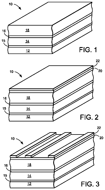
Integrated circuit with self-aligned line and via
An integrated circuit is provided having a base with a first dielectric layer formed thereon.
US 8,766,534 B2 · Assignee: Idemitsu Kosan Co., Ltd. · Inventors: Fukuoka; Kenichi et al.
Sheet 1 of 3 from the published document. All sheets in the USPTO PDF
An organic electroluminescence element comprising: an anode; a first emitting layer comprising at least a first host material and a first dopant; a second emitting layer comprising at least a second host material and a second dopant; and a cathode in the order mentioned: wherein the energy gap E.sub.gh1 of the first host material, the energy gap E.sub.gd1 of the first dopant, the energy gap E.sub.gh2 of the second host material, and the energy gap E.sub.gd2 of the second dopant satisfy the following formulas; and the luminescent intensity I1 at the maximum luminescent wavelength of an emission spectrum derived from the first emitting layer, and the luminescent intensity I2 at the maximum luminescent wavelength of an emission spectrum derived from the second emitting layer satisfy the following formula: E.sub.gh1>E.sub.gd1 E.sub.gh2>E.sub.gd2 E.sub.gd1>E.sub.gd2 I1>3.5.times.I2.
Electroluminescence elements, which uses electroluminescence (electroluminescence being abbreviated to "EL" hereinafter), have a high visibility because of spontaneous emission and further have good features, such as excellent impact resistance, because they are completely solid elements. Therefore, attention has been paid to the use thereof as light emitting elements in various display devices. The EL elements are classified into inorganic EL elements, wherein an inorganic compound is used for their luminescent material, and organic EL elements, wherein an organic compound is used therefor. In particular, the organic EL elements are being developed as next-generation light emitting elements since the elements enable to reduce the voltage to be applied largely, easily enable the formation of full-color devices, are small in power consumption and make panel-emission possible. An organic E
1 of 3 drawing sheets so far from the published document, cropped to the drawing. Every sheet is in the USPTO PDF.
What the patent claimed, word for word. All of it is now free to use.
The present invention relates to an organic electroluminescence element and, specifically, an organic electroluminescence element comprising an emitting layer having a bi-layered structure.
Electroluminescence elements, which uses electroluminescence (electroluminescence being abbreviated to "EL" hereinafter), have a high visibility because of spontaneous emission and further have good features, such as excellent impact resistance, because they are completely solid elements. Therefore, attention has been paid to the use thereof as light emitting elements in various display devices.
The EL elements are classified into inorganic EL elements, wherein an inorganic compound is used for their luminescent material, and organic EL elements, wherein an organic compound is used therefor. In particular, the organic EL elements are being developed as next-generation light emitting elements since the elements enable to reduce the voltage to be applied largely, easily enable the formation of full-color devices, are small in power consumption and make panel-emission possible.
An organic EL element basically has a structure of an anode/an emitting layer/a cathode, as illustrated in FIG. 3.
This organic EL element 10 has an emitting layer 14 sandwiched between a pair of electrodes composed of an anode 12 and a cathode 13. The emitting layer 14 is usually composed of plural laminated layers. When an electric field is applied across the electrodes 12 and 13 in this element 10, electrons are injected from the cathode 13 and holes are injected from the anode 12. The electrons and the holes are recombined in the emitting layer 14 so as to cause an exciting state. When the exciting state returns to a ground state, energy is emitted as light.
FIG. 4 shows an energy diagram of the organic EL element in FIG. 3. In FIG. 4, a valence electron level EV0 (HOMO) and a conduction level EC0 (LUMO), which are energy levels of the emitting layer 14, are shown. Holes go in the layer 14 from the anode 12 and electrons go therein from the cathode 13. The holes and the electrons are combined with each other in the layer 14 so as to emit light.
There is known an element wherein the above-mentioned structure is used as a base and a hole injecting.cndot.transporting layer and/or an electron injecting layer are appropriately added, an example of the element being an element having the following structure: an anode/a hole injecting.cndot.transporting layer/an emitting layer/a cathode; or an anode/a hole injecting layer/a hole transporting layer/an emitting layer/an electron injecting layer/a cathode.
The emitting layer has the following functions:
Injecting function: a function capable of injecting holes into the layer from an anode or a hole injecting layer, and injecting electrons into the layer from a cathode or an electron injecting layer when an electric field is applied.
Transporting function: a function of transporting the injected charges (electrons and holes) by the electric field.
Light emitting functions: a function of supplying a field where the electrons and the holes are recombined and inducing light emission from this recombination.
The hole injecting.cndot.transporting layer has a function of injecting holes into the layer from an anode and transporting the holes into an organic emitting layer. A hole injecting layer and a hole transporting layer may be separately formed. The electron injecting layer has a function of injecting electrons into the layer from a cathode, and transporting the electrons into the organic emitting layer.
In order to make light emission in the emitting layer more intense, a technique of adding a very small amount of a fluorescent molecule (dopant) thereto is known.
FIG. 5 illustrates an energy diagram of an organic EL element to which a dopant is added. In this figure, ECh represents the conduction level of the host thereof; EVh, the valence electron level of the host; ECd, the conduction level of the dopant; and EVd, the valence electron level of the dopant. Egh and Egd represent the energy gap (difference between the ECh and the EVh) of the host and the energy gap (difference between the ECd and the EVd) of the dopant, respectively.
The dopant receives the energy of the excited host effectively so as to enhance the light emitting efficiency.
The method for obtaining multicolor from the luminescence of an organic EL element is roughly classified into the following three methods:
A method of taking out lights of three colors from white luminescence emitted from an organic EL element by using three colors, red, green and blue filters.
A method of converting blue luminescence emitted from an blue EL element to light of other colors by a fluorescent layer formed on the light-taking-out side of its emitting layer.
A method of arranging blue, red and green emitting layers side by side on the same substrate.
For these methods, organic EL elements giving a high luminance and having a long durability have been demanded. For example, for the methods
and (2), the following has been earnestly desired: organic EL elements which emit light having a bluish green or white broad band (wide spectrum) and which have a half life of several ten thousands of hours or more for an initial luminance of several hundreds nit.
Various element structures have been investigated for such a desire.
As one method out of them, a method for making an organic emitting layer into plural layers, thereby obtaining white or broad band luminescence is suggested as follows:
A way of making an organic emitting layer into a bi-layered structure, the first emitting layer in the anode side thereof being a blue emitting layer made of an aluminum complex compound, and the second emitting layer in the cathode side being a red emitting layer made of an aluminum complex compound containing a red fluorescent material, thereby taking out white light (see, for example, EP0643549).
A way of making an organic emitting layer into a bi-layered structure, the first emitting layer in the anode side thereof being a blue emitting layer made of a distyrylarylene-based compound, and the second emitting layer in the cathode side being an emitting layer wherein a red fluorescent material is added to an aluminum complex compound emitting green light, thereby taking out white light (see, for example, U.S. Pat. No. 5,503,910).
A way of incorporating coumarin and rubrene as dopants into an emitting layer which is a mixture layer of an electron transporting compound made of an aluminum complex and a hole transporting compound made of a diamine compound, thereby emitting light having a green component and an orange component (see, for example, WO98/08360).
A way of doping a host material made of a distyrylarylene-based compound with two or more fluorescent materials different in color, thereby forming two emitting layers (see, for example, JP-A-12-68057).
These conventional techniques are ways for causing plural kinds of dopants equally to emit light to obtain broad band or white luminescence. The light emitted from the organic EL element is light wherein various wavelengths are mixed.
However, there is not known any organic EL element which has a multi-layered, laminated structure, emits light with a high color purity and a narrow band (narrow spectrum), and has a long durability.
In light of the above-mentioned problems, an object of the present invention is to provide an organic EL element which emits light with a high color purity and a narrow band and has a long durability.
Disclosure of the Invention
In order to solve the problems, the present inventors have found out that in an organic EL element having at least two emitting layers, the light emission of the second emitting layer is restrained or the two emitting layers satisfy a given relationship, whereby the color purity and/or durability of the element can be improved.
The present invention provides the following EL elements. [1] An organic electroluminescence element comprising:
an anode;
a first emitting layer comprising at least a first host material and a first dopant;
a second emitting layer comprising at least a second host material and a second dopant; and
a cathode in the order mentioned:
wherein the energy gap E.sub.gh1 of the first host material, the energy gap E.sub.gd1 of the first dopant, the energy gap E.sub.gh2 of the second host material, and the energy gap E.sub.gd2 of the second dopant satisfy the following formulas; and
the luminescent intensity I1 at the maximum luminescent wavelength of an emission spectrum derived from the first emitting layer, and the luminescent intensity I2 at the maximum luminescent wavelength of an emission spectrum derived from the second emitting layer satisfy the following formula: E.sub.gh1>E.sub.gd1 E.sub.gh2>E.sub.gd2 E.sub.gd1>E.sub.gd2 I1>3.5.times.I2. [2] An organic electroluminescence element according to [1], wherein the following formula is satisfied: I1>5.times.I2. [3] An organic electroluminescence element according to [1] or [2], wherein E.sub.gd2 is more than 2.7 eV. [4] An organic electroluminescence element comprising:
an anode;
a first emitting layer comprising at least a first host material and a first dopant;
a second emitting layer comprising at least a second host material and a second dopant; and
a cathode in the order mentioned:
wherein the energy gap E.sub.gh1 of the first host material, the energy gap E.sub.gd1 of the first dopant, the energy gap E.sub.gh2 of the second host material, and the energy gap E.sub.gd2 of the second dopant satisfy the following formulas: E.sub.gh1>E.sub.gd1 E.sub.gh2>E.sub.gd2 E.sub.gd1>E.sub.gd2 >2.7 eV. [5] An organic electroluminescence element according to any one of [1] to [4], wherein the ratio of the first dopant to the first host material is 0.1 to 10 mol % in the first emitting layer. [6] An organic electroluminescence element according to any one of [1] to [5], wherein the ratio of the second dopant to the second host material is 0.1 to 10 mol % in the second emitting layer. [7] An organic electroluminescence element according to any one of [1] to [6], wherein at least one of the first host material and the second host material is a compound represented by a formula [1]:
##STR00001## wherein Ar.sup.1 is an aromatic ring with 6 to 50 nucleus carbons, X is a substituent, m is an integer of 1 to 5 and n is an integer of 0 to 6, provided that Ars may be the same as or different from each other when m is 2 or more, and Xs may be the same as or different from each other when n is 2 or more. [8] An organic electroluminescence element according to any one of [1] to [7], wherein the first host material is the same as the second host material. [9] An organic electroluminescence element according to any one of [1] to [8], wherein at least one of the first dopant and the second dopant is a compound represented by a formula [2]:
##STR00002## wherein Ar.sup.2 to Ar.sup.4 are a substituted or unsubstituted aromatic group with 6 to 50 nucleus carbons, or a substituted or unsubstituted stylyl group; and p is an integer of 1 to 4; provided that Ar.sup.3s and Ar.sup.4s may be the same as or different from each other when p is 2 or more. [10] An organic electroluminescence element according to any one of [1] to [9], wherein the first emitting layer has a film thickness of 10 nm or more. [11] An organic electroluminescence element according to any one of [1] to [10], wherein the luminescent intensity I2 at the maximum luminescent wavelength of an emission spectrum derived from the second emitting layer is 0. [12] An organic electroluminescence element according to any one of [1] to [11], further comprising an electron injecting layer between the second emitting layer and the cathode, the electron mobility of the electron injecting layer being 10.sup.-4 cm.sup.2/(Vsec) or more. [13] An organic electroluminescence element according to [12], wherein the electron injecting layer comprises one or more organic compounds comprising a nitrogen-containing heterocyclic derivative. [14] An organic electroluminescence element according to [13], wherein the organic compound(s) is/are an imidazopyrazine derivative and/or an imidazole derivative.
FIG. 1 is a schematic sectional view of an organic EL element of the present invention.
FIG. 2 is the energy diagram of the organic EL element of the present invention.
FIG. 3 is a schematic sectional view of an ordinary organic EL element.
FIG. 4 is the energy diagram of the organic EL element.
FIG. 5 is the energy diagram of an organic EL element to which a dopant is added.
The present invention is described in detail hereinafter.
A first organic EL element of the present invention comprises an anode, a first emitting layer comprising at least a first host material and a first dopant, a second emitting layer comprising at least a second host material and a second dopant, and a cathode in the order mentioned, wherein the energy gap E.sub.gh1 of the first host material, the energy gap E.sub.gd1 of the first dopant, the energy gap E.sub.gh2 of the second host material, and the energy gap E.sub.gd2 of the second dopant satisfy the following formulas; and the luminescent intensity I1 at the maximum luminescent wavelength of an emission spectrum derived from the first emitting layer, and the luminescent intensity I2 at the maximum luminescent wavelength of an emission spectrum derived from the second emitting layer satisfy the following formulas: E.sub.gh1>E.sub.gd1 E.sub.gh2>E.sub.gd2 E.sub.gd1>E.sub.gd2 I1>3.5.times.I2.
FIG. 1 is a schematic sectional view of an organic EL element of the present invention.
The organic EL element 1 has at least an anode 2, a first emitting layer 3, a second emitting layer 4, and a cathode 5, and these are laminated in the order mentioned.
FIG. 2 is the energy diagram of the organic EL element 1.
In this energy diagram, energy levels of the anode 2, the first emitting layer 3, the second emitting layer 4, and the cathode 5 are shown. The following are also shown: the energy gap E.sub.gh1 of the first host material, the energy gap E.sub.gd1 of the first dopant, the energy gap E.sub.gh2 of the second host material, and the energy gap E.sub.gd2 of the second dopant.
The energy gap corresponds to the energy difference between the valence electron level of an organic EL material and the conduction level thereof, and is usually obtained from an absorption edge of the optical absorption spectrum of the material.
As shown in FIG. 2, in the present invention, an emitting layer is made into a bi-layered structure and the different emitting layers 3 and 4 are doped with the first dopant and the second dopant, respectively, the first emitting layer 3 containing the dopant with a large energy gap mainly emitting light.
In general, when two kinds of dopants are incorporated into a single emitting layer, energy shift is easily caused since the distance between these dopants is small. Usually, therefore, each of the two kinds of dopants emits light or only the dopant having a smaller energy gap emits light. It is very difficult to cause only the dopant having a larger energy gap to emit light.
However, as understood from the conventional art, only by making an emitting layer into a bi-layered structure, both of the first emitting layer 3 and the second emitting layer 4 emit light. Therefore light with a narrow band leading to a high purity of color is not obtained.
One of the causes thereof is position where holes and electrons are recombined. Holes injected into the emitting layer are recombined with electrons, whereby the concentration thereof becomes lower as the holes advance further toward the cathode 5. However, a part thereof reach the vicinity of the cathode 5. Accordingly, a recombining region is present near the cathode 5 also. This causes light emission of both of the first emitting layer 3 (emitting layer near the anode 2) and the second emitting layer 4 (emitting layer near the cathode 5).
Thus, in order to restrain light emission of the emitting layer containing a dopant having a small energy gap, the emission being a cause of lowering the purity of color, the first emitting layer 3 is formed near the anode 2 where a recombination possibility is high, and the second light emitting 4 is formed near the cathode 5 where a recombination possibility is low. This makes it possible that light is emitted mainly by the first emitting layer 3 and that light emission of the second emitting layer 4 is sufficiently reduced.
Furthermore, in the present invention, an electron injecting layer is formed between the second emitting layer 4 and the cathode 5. The electron mobility of this electron injecting layer is preferably 10.sup.-4 cm.sup.2/Vsecond or more in an electric field having an electric field intensity (E) of 1.times.10.sup.5 to 10.sup.6 V/cm.
The electron injecting layer having such an electron mobility enables the more stable formation of a light emitting region in the first emitting layer 3. Accordingly, the first emitting layer 3 can emit light more selectively, so that narrow band luminescence better in color purity can be obtained. Additionally, the durability of the EL element can be made remarkably long.
As a method for measuring the electron mobility, the following is known: the time of flight method (the method of calculating the mobility from the measurement of the running time of charges in an organic film), a method of calculating the mobility from the voltage characteristic of space limitation electric current, or the like [see Electronic Process in Organic Crystals (M. Pope, C. E. Swenberg), and Organic Molecular Solids (W. Jones)]
In the specification, it is calculated by the time of flight method. Specifically, for a laminate of ITO/an organic layer (such as an electron injecting layer)/Al, the time characteristic (the transient characteristic time) of the transient current generated by radiation of light is measured and then the electron mobility is calculated from the following equation: Electron mobility=(Organic layer thickness).sup.2/(Transient characteristic time.times.Electric field intensity)
In general, the number of materials having a large energy gap and having a long half life is smaller than that of materials having a small energy gap and having a long half life. Thus, the selection of a material therefrom is difficult. However, this structure allows the longer durability of the organic EL element although the second emitting layer hardly contributes to light emission.
In this organic EL element 1, the energy gap (E.sub.gh1) of the first host material is larger than the energy gap (E.sub.gd1) of the first dopant. That is, the relationship of E.sub.gh1>E.sub.gd1 is satisfied.
The energy gap E.sub.gd1 of the first dopant is preferably more than 2.7 eV. In general, the number of dopants having a large energy gap and giving a short durability to organic EL elements is larger than that of dopants having a small energy gap and giving a short durability to organic EL elements. Therefore, for purely blue organic EL elements used for full color display, it is difficult that the durability thereof is made long. In the present invention, however, purely blue luminescence having a very long durability can be obtained by the above-mentioned structure.
The second emitting layer comprises at least a second host material and a second dopant.
The energy gap E.sub.gh2 of the second host material is larger than the energy gap E.sub.gd2 of the second dopant. That is, the relationship of E.sub.gh2>E.sub.gd2 is satisfied.
The energy gap E.sub.gd1 of the first dopant is larger than the energy gap E.sub.gd2 of the second dopant, that is, the relationship of E.sub.gd1>E.sub.gd2 is satisfied.
It is also preferred that the energy gap E.sub.gd2 of the second dopant is larger than 2.7 eV, that is, the relationship of E.sub.gd2>2.7 eV is satisfied. This enables the production of an organic EL element which emits blue light high in color purity for full color display.
In this organic EL element, the luminescent intensity I1 at the maximum luminescent wavelength of an emission spectrum derived from the first emitting layer and the luminescent intensity I2 at the maximum luminescent wavelength of an emission spectrum derived from the second emitting layer satisfy the relationship of I1>3.5.times.I2. When this relationship is satisfied, narrow band luminescence good in color purity can be obtained. Preferably, I1>5.times.I2. More preferably, I1>10.times.I2. It is in particular preferred that the luminescent intensity I2 from the second emitting layer is 0.
As described above, the durability of an organic EL element can be made long even when the luminescence of its second emitting layer hardly contributes to the luminescence of the whole of the organic EL element.
In general, as materials have a smaller energy gap, a larger number of the materials have a long durability. Thus, the selection of a material therefrom is easy. Accordingly, about EL elements for broad band luminescence or white luminescence, it is relatively easy to make a long-durability element structure.
However, it is difficult to select a long-durability material for narrow band luminescence, in particular, blue luminescence. In particular, purely blue luminescent materials suitable for full color use have hardly been reported so far. The present invention is a technique for elongating the durability of purely blue luminescent materials which have been hitherto known. In other words, the present invention is a technique of daring to using a material the durability of which is known to be long adjacently to an emitting layer and further restricting luminescence therefrom as much as possible, thereby making the durability of the EL element long.
A second organic EL element of the present invention comprises an anode, a first emitting layer comprising at least a first host material and a first dopant, a second emitting layer comprising at least a second host material and a second dopant, and a cathode in the order mentioned, wherein the energy gap E.sub.gh1 of the first host material, the energy gap E.sub.gd1 of the first dopant, the energy gap E.sub.gh2 of the second host material, and the energy gap E.sub.gd2 of the second dopant satisfy the following formulas: E.sub.gh1>E.sub.gd1, E.sub.gh2>E.sub.gd2, and E.sub.gd1>E.sub.gd2>2.7 eV.
Accordingly, the basic structure thereof is the same as that of the organic EL element described above.
This organic EL element satisfies the relationship of: E.sub.gd1>E.sub.gd2>2.7 eV. This relationship is satisfied; therefore, even if both of the first and second emitting layers emit light, both of them emit blue light, which is different from the above-mentioned organic EL element. Consequently, blue luminescence high in color purity can be obtained.
Furthermore, such an element structure makes it possible to make the durability of the organic EL element long in the same manner as in the first invention.
The host materials used in the first and second emitting layers may each be a material known as a luminescent material having a long durability. It is preferred to use, as the host material of the luminescent material, a material represented by a general formula [1]:
##STR00003## wherein Ar.sup.1 is an aromatic ring with 6 to 50 nucleus carbons, X is a substituent, m is integer of 1 to 5, and n is an integer of 0 to 6, provided that Ar.sup.1s may be the same as or different from each other when m is 2 or more, and Xs may be the same as or different from each other when n is 2 or more.
Specific examples of Ar.sup.1 include phenyl, naphthyl, anthracene, biphenylene, azulene, acenaphthylene, fluorene, phenanthrene, fluoranthene, acephenanthrylene, triphenylene, pyrene, chrysene, naphthacene, picene, perylene, penthaphene, pentacene, tetraphenylene, hexaphene, hexacene, rubicene, coronene, and trinaphthylene rings.
Preferred examples thereof include phenyl, naphthyl, anthracene, acenaphthylene, fluorene, phenanthrene, fluoranthene, triphenylene, pyrene, chrysene, perylene, and trinaphthylene rings.
More preferred examples thereof include phenyl, naphthyl, anthracene, fluorene, phenanthrene, fluoranthene, pyrene, chrysene, and perylene rings.
Specific examples of X include substituted or unsubstituted aromatic groups with 6 to 50 nucleus carbons, substituted or unsubstituted aromatic heterocyclic groups with 5 to 50 nucleus carbons, substituted or unsubstituted alkyl groups with 1 to 50 carbons, substituted or unsubstituted alkoxy groups with 1 to 50 carbons, substituted or unsubstituted aralkyl groups with 1 to 50 carbons, substituted or unsubstituted aryloxy groups with 5 to 50 nucleus atoms, substituted or unsubstituted arylthio groups with 5 to 50 nucleus atoms, substituted or unsubstituted carboxyl groups with 1 to 50 carbons, substituted or unsubstituted styryl groups, halogen groups, a cyano group, a nitro group, and a hydroxyl group.
Examples of the substituted or unsubstituted aromatic groups with 6 to 50 nucleus carbons include phenyl, 1-naphthyl, 2-naphthyl, 1-anthryl, 2-anthryl, 9-anthryl, 1-phenanthryl, 2-phenanthryl, 3-phenanthryl, 4-phenanthryl, 9-phenanthryl, 1-naphthacenyl, 2-naphthacenyl, 9-naphthacenyl, 1-pyrenyl, 2-pyrenyl, 4-pyrenyl, 2-biphenylyl, 3-biphenylyl, 4-biphenylyl, p-terphenyl-4-yl, p-terphenyl-3-yl, p-terphenyl-2-yl, m-terphenyl-4-yl, m-terphenyl-3-yl, m-terphenyl-2-yl, o-tolyl, m-tolyl, p-tolyl, p-t-butylphenyl, p-(2-phenylpropyl)phenyl, 3-methyl-2-naphthyl, 4-methyl-1-naphthyl, 4-methyl-1-anthryl, 4'-methylbiphenylyl, 4''-t-butyl-p-terphenyl-4-yl, 2-fluorenyl, 9,9-dimethyl-2-fluorenyl and 3-fluorantenyl groups.
Preferred examples thereof include phenyl, 1-naphthyl, 2-naphthyl, 9-phenanthryl, 1-naphthacenyl, 2-naphthacenyl, 9-naphthacenyl, 1-pyrenyl, 2-pyrenyl, 4-pyrenyl, 2-biphenylyl, 3-biphenylyl, 4-biphenylyl, o-tolyl, m-tolyl, p-tolyl, p-t-butylphenyl, 2-fluorenyl, 9,9-dimethyl-2-fluorenyl and 3-fluorantenyl groups.
Examples of the substituted or unsubstituted aromatic heterocyclic groups with 5 to 50 nucleus carbons include 1-pyrrolyl, 2-pyrrolyl, 3-pyrrolyl, pyrazinyl, 2-pyridinyl, 3-pyridinyl, 4-pyridinyl, 1-indolyl, 2-indolyl, 3-indolyl, 4-indolyl, 5-indolyl, 6-indolyl, 7-indolyl, 1-isoindolyl, 2-isoindolyl, 3-isoindolyl, 4-isoindolyl, 5-isoindolyl, 6-isoindolyl, 7-isoindolyl, 2-furyl, 3-furyl, 2-benzofuranyl, 3-benzofuranyl, 4-benzofuranyl, 5-benzofuranyl, 6-benzofuranyl, 7-benzofuranyl, 1-isobenzofuranyl, 3-isobenzofuranyl, 4-isobenzofuranyl, 5-isobenzofuranyl, 6-isobenzofuranyl, 7-isobenzofuranyl, quinolyl, 3-quinolyl, 4-quinolyl, 5-quinolyl, 6-quinolyl, 7-quinolyl, 8-quinolyl, 1-isoquinolyl, 3-isoquinolyl, 4-isoquinolyl, 5-isoquinolyl, 6-isoquinolyl, 7-isoquinolyl, 8-isoquinolyl, 2-quinoxalinyl, 5-quinoxalinyl, 6-quinoxalinyl, 1-carbazolyl, 2-carbazolyl, 3-carbazolyl, 4-carbazolyl, 9-carbazolyl, 1-phenanthrydinyl, 2-phenanthrydinyl, 3-phenanthrydinyl, 4-phenanthrydinyl, 6-phenanthrydinyl, 7-phenanthrydinyl, 8-phenanthrydinyl, 9-phenanthrydinyl, 10-phenanthrydinyl, 1-acrydinyl, 2-acrydinyl, 3-acrydinyl, 4-acrydinyl, 9-acrydinyl, 1,7-phenanthroline-2-yl, 1,7-phenanthroline-3-yl, 1,7-phenanthroline-4-yl, 1,7-phenanthroline-5-yl, 1,7-phenanthroline-6-yl, 1,7-phenanthroline-8-yl, 1,7-phenanthroline-9-yl, 1,7-phenanthroline-10-yl, 1,8-phenanthroline-2-yl, 1,8-phenanthroline-3-yl, 1,8-phenanthroline-4-yl, 1,8-phenanthroline-5-yl, 1,8-phenanthroline-6-yl, 1,8-phenanthroline-7-yl, 1,8-phenanthroline-9-yl, 1,8-phenanthroline-10-yl, 1,9-phenanthroline-2-yl, 1,9-phenanthroline-3-yl, 1,9-phenanthroline-4-yl, 1,9-phenanthroline-5-yl, 1,9-phenanthroline-6-yl, 1,9-phenanthroline-7-yl, 1,9-phenanthroline-8-yl, 1,9-phenanthroline-10-yl, 1,10-phenanthroline-2-yl, 1,10-phenanthroline-3-yl, 1,10-phenanthroline-4-yl, 1,10-phenanthroline-5-yl, 2,9-phenanthroline-1-yl, 2,9-phenanthroline-3-yl, 2,9-phenanthroline-4-yl, 2,9-phenanthroline-5-yl, 2,9-phenanthroline-6-yl, 2,9-phenanthroline-7-yl, 2,9-phenanthroline-8-yl, 2,9-phenanthroline-10-yl, 2,8-phenanthroline-1-yl, 2,8-phenanthroline-3-yl, 2,8-phenanthroline-4-yl, 2,8-phenanthroline-5-yl, 2,8-phenanthroline-6-yl, 2,8-phenanthroline-7-yl, 2,8-phenanthroline-9-yl, 2,8-phenanthroline-10-yl, 2,7-phenanthroline-1-yl, 2,7-phenanthroline-3-yl, 2,7-phenanthroline-4-yl, 2,7-phenanthroline-5-yl, 2,7-phenanthroline-6-yl, 2,7-phenanthroline-8-yl, 2,7-phenanthroline-9-yl, 2,7-phenanthroline-10-yl, 1-phenazinyl, 2-phenazinyl, 1-phenothiazinyl, 2-phenothiazinyl, 3-phenothiazinyl, 4-phenothiazinyl, 10-phenothiazinyl, 1-phenoxazinyl, 2-phenoxazinyl, 3-phenoxazinyl, 4-phenoxazinyl, 10-phenoxazinyl, 2-oxazolyl, 4-oxazolyl, 5-oxazolyl, 2-oxadiazolyl, 5-oxadiazolyl, 3-furazanyl, 2-thienyl, 3-thienyl, 2-methylpyrrole-1-yl, 2-methylpyrrole-3-yl, 2-methylpyrrole-4-yl, 2-methylpyrrole-5-yl, 3-methylpyrrole-1-yl, 3-methylpyrrole-2-yl, 3-methylpyrrole-4-yl, 3-methylpyrrole-5-yl, 2-t-butylpyrrole-4-yl, 3-(2-phenylpropyl)pyrrole-1-yl, 2-methyl-1-indolyl, 4-methyl-1-indolyl, 2-methyl-3-indolyl, 4-methyl-3-indolyl, 2-t-butyl 1-indolyl, 4-t-butyl 1-indolyl, 2-t-butyl 3-indolyl, and 4-t-butyl 3-indolyl groups.
Examples of the substituted or unsubstituted alkyl groups with 1 to 50 carbons include methyl, ethyl, propyl, isopropyl, n-butyl, s-butyl, isobutyl, t-butyl, n-pentyl, n-hexyl, n-heptyl, n-octyl, hydroxymethyl, 1-hydroxyethyl, 2-hydroxyethyl, 2-hydroxyisobutyl, 1,2-dihydroxyethyl, 1,3-dihydroxyisopropyl, 2,3-dihydroxy-t-butyl, 1,2,3-trihydroxypropyl, chloromethyl, 1-chloroethyl, 2-chloroethyl, 2-chloroisobutyl, 1,2-dichloroethyl, 1,3-dichloroisopropyl, 2,3-dichloro-t-butyl, 1,2,3-trichloropropyl, bromomethyl, 1-bromoethyl, 2-bromoethyl, 2-bromoisobutyl, 1,2-dibromoethyl, 1,3-dibromoisopropyl, 2,3-dibromo-t-butyl, 1,2,3-tribromopropyl, iodomethyl, 1-iodoethyl, 2-iodoethyl, 2-iodoisobutyl, 1,2-diiodoethyl, 1,3-diiodoisopropyl, 2,3-diiodo-t-butyl, 1,2,3-triiodopropyl, aminomethyl, 1-aminoethyl, 2-aminoethyl, 2-aminoisobutyl, 1,2-diaminoethyl, 1,3-diaminoisopropyl, 2,3-diamino-t-butyl, 1,2,3-triaminopropyl, cyanomethyl, 1-cyanoethyl, 2-cyanoethyl, 2-cyanoisobutyl, 1,2-dicyanoethyl, 1,3-dicyanoisopropyl, 2,3-dicyano-t-butyl, 1,2,3-tricyanopropyl, nitromethyl, 1-nitroethyl, 2-nitroethyl, 2-nitroisobutyl, 1,2-dinitroethyl, 1,3-dinitroisopropyl, 2,3-dinitro-t-butyl, 1,2,3-trinitropropyl, cyclopropyl, cyclobutyl, cyclopentyl, cyclohexyl, 4-methylcyclohexyl, 1-adamanthyl, 2-adamanthyl, 1-norbornyl, and 2-norbornyl groups.
The substituted or unsubstituted alkoxy groups with 1 to 50 carbons are groups represented by --OY. Examples of Y include methyl, ethyl, propyl, isopropyl, n-butyl, s-butyl, isobutyl, t-butyl, n-pentyl, n-hexyl, n-heptyl, n-octyl, hydroxymethyl, 1-hydroxyethyl, 2-hydroxyethyl, 2-hydroxyisobutyl, 1,2-dihydroxyethyl, 1,3-dihydroxyisopropyl, 2,3-dihyroxy-t-butyl, 1,2,3-trihydroxypropyl, chloromethyl, 1-chloroethyl, 2-chloroethyl, 2-chloroisobutyl, 1,2-dichloroethyl, 1,3-dichloroisopropyl, 2,3-dichloro-t-butyl, 1,2,3-trichloropropyl, bromomethyl, 1-bromoethyl, 2-bromoethyl, 2-bromoisobutyl, 1,2-dibromoethyl, 1,3-dibromoisopropyl, 2,3-dibromo-t-butyl, 1,2,3-tribromopropyl, iodomethyl, 1-iodoethyl, 2-iodoethyl, 2-iodoisobutyl, 1,2-diiodoethyl, 1,3-diiodoisopropyl, 2,3-diiodo-t-butyl, 1,2,3-triiodopropyl, aminomethyl, 1-aminoethyl, 2-aminoethyl, 2-aminoisobutyl, 1,2-diaminoethyl, 1,3-diaminoisopropyl, 2,3-diamino-t-butyl, 1,2,3-triaminopropyl, cyanomethyl, 1-cyanoethyl, 2-cyanoethyl, 2-cyanoisobutyl, 1,2-dicyanoethyl, 1,3-dicyanoisopropyl, 2,3-dicyano-t-butyl, 1,2,3-tricyanopropyl, nitromethyl, 1-nitroethyl, 2-nitroethyl, 2-nitroisobutyl, 1,2-dinitroethyl, 1,3-dinitroisopropyl, 2,3-dinitro-t-butyl, and 1,2,3-trinitropropyl groups.
Examples of the substituted or unsubstituted aralkyl groups with 1 to 50 carbons include benzyl, 1-phenylethyl, 2-phenylethyl, 1-phenylisopropyl, 2-phenylisopropyl, phenyl-t-butyl, .alpha.-naphthylmethyl, 1-.alpha.-naphthylethyl, 2-.alpha.-naphthylethyl, 1-.alpha.-naphthylisopropyl, 2-.alpha.-naphthylisopropyl, .beta.-naphthylmethyl, 1-.beta.-naphthylethyl, 2-.beta.-naphthylethyl, 1-.beta.-naphthylisopropyl, 2-.beta.-naphthylisopropyl, 1-pyrrolylmethyl, 2-(1-pyrrolyl)ethyl, p-methylbenzyl, m-methylbenzyl, o-methylbenzyl, p-chlorobenzyl, m-chlorobenzyl, o-chlorobenzyl, p-bromobenzyl, m-bromobenzyl, o-bromobenzyl, p-iodobenzyl, m-iodobenzyl, o-iodobenzyl, p-hydroxybenzyl, m-hydroxybenzyl, o-hydroxybenzyl, p-aminobenzyl, m-aminobenzyl, o-aminobenzyl, p-nitrobenzyl, m-nitrobenzyl, o-nitrobenzyl, p-cyanobenzyl, m-cyanobenzyl, o-cyanobenzyl, 1-hydroxy-2-phenylisopropyl, and 1-chloro-2-phenylisopropyl groups.
The substituted or unsubstituted aryloxy groups with 5 to 50 nucleus atoms are represented by --OY'. Examples of Y' include phenyl, 1-naphthyl, 2-naphthyl, 1-anthryl, 2-anthryl, 9-anthryl, 1-phenanthryl, 2-phenanthryl, 3-phenanthryl, 4-phenanthryl, 9-phenanthryl, 1-naphthacenyl, 2-naphthacenyl, 9-naphthacenyl, 1-pyrenyl, 2-pyrenyl, 4-pyrenyl, 2-biphenylyl, 3-biphenylyl, 4-biphenylyl, p-terphenyl-4-yl, p-terphenyl-3-yl, p-terphenyl-2-yl, m-terphenyl-4-yl, m-terphenyl-3-yl, m-terphenyl-2-yl, o-tolyl, m-tolyl, p-tolyl, p-t-butylphenyl, p-(2-phenylpropyl)phenyl, 3-methyl-2-naphthyl, 4-methyl-1-naphthyl, 4-methyl-1-anthryl, 4'-methylbiphenylyl, 4''-t-butyl-p-terphenyl-4-yl, 2-pyrrolyl, 3-pyrrolyl, pyrazinyl, 2-pyridinyl, 3-pyridinyl, 4-pyridinyl, 2-indolyl, 3-indolyl, 4-indolyl, 5-indolyl, 6-indolyl, 7-indolyl, 1-isoindolyl, 3-isoindolyl, 4-isoindolyl, 5-isoindolyl, 6-isoindolyl, 7-isoindolyl, 2-furyl, 3-furyl, 2-benzofuranyl, 3-benzofuranyl, 4-benzofuranyl, 5-benzofuranyl, 6-benzofuranyl, 7-benzofuranyl, 1-isobenzofuranyl, 3-isobenzofuranyl, 4-isobenzofuranyl, 5-isobenzofuranyl, 6-isobenzofuranyl, 7-isobenzofuranyl, 2-quinolyl, 3-quinolyl, 4-quinolyl, 5-quinolyl, 6-quinolyl, 7-quinolyl, 8-quinolyl, 1-isoquinolyl, 3-isoquinolyl, 4-isoquinolyl, 5-isoquinolyl, 6-isoquinolyl, 7-isoquinolyl, 8-isoquinolyl, 2-quinoxalinyl, 5-quinoxalinyl, 6-quinoxalinyl, 1-carbazolyl, 2-carbazolyl, 3-carbazolyl, 4-carbazolyl, 1-phenanthrydinyl, 2-phenanthrydinyl, 3-phenanthrydinyl, 4-phenanthrydinyl, 6-phenanthrydinyl, 7-phenanthrydinyl, 8-phenanthrydinyl, 9-phenanthrydinyl, 10-phenanthrydinyl, 1-acrydinyl, 2-acrydinyl, 3-acrydinyl, 4-acrydinyl, 9-acrydinyl, 1,7-phenanthroline-2-yl, 1,7-phenanthroline-3-yl, 1,7-phenanthroline-4-yl, 1,7-phenanthroline-5-yl, 1,7-phenanthroline-6-yl, 1,7-phenanthroline-8-yl, 1,7-phenanthroline-9-yl, 1,7-phenanthroline-10-yl, 1,8-phenanthroline-2-yl, 1,8-phenanthroline-3-yl, 1,8-phenanthroline-4-yl, 1,8-phenanthroline-5-yl, 1,8-phenanthroline-6-yl, 1,8-phenanthroline-7-yl, 1,8-phenanthroline-9-yl, 1,8-phenanthroline-10-yl, 1,9-phenanthroline-2-yl, 1,9-phenanthroline-3-yl, 1,9-phenanthroline-4-yl, 1,9-phenanthroline-5-yl, 1,9-phenanthroline-6-yl, 1,9-phenanthroline-7-yl, 1,9-phenanthroline-8-yl, 1,9-phenanthroline-10-yl, 1,10-phenanthroline-2-yl, 1,10-phenanthroline-3-yl, 1,10-phenanthroline-4-yl, 1,10-phenanthroline-5-yl, 2,9-phenanthroline-1-yl, 2,9-phenanthroline-3-yl, 2,9-phenanthroline-4-yl, 2,9-phenanthroline-5-yl, 2,9-phenanthroline-6-yl, 2,9-phenanthroline-7-yl, 2,9-phenanthroline-8-yl, 2,9-phenanthroline-10-yl, 2,8-phenanthroline-1-yl, 2,8-phenanthroline-3-yl, 2,8-phenanthroline-4-yl, 2,8-phenanthroline-5-yl, 2,8-phenanthroline-6-yl, 2,8-phenanthroline-7-yl, 2,8-phenanthroline-9-yl, 2,8-phenanthroline-10-yl, 2,7-phenanthroline-1-yl, 2,7-phenanthroline-3-yl, 2,7-phenanthroline-4-yl, 2,7-phenanthroline-5-yl, 2,7-phenanthroline-6-yl, 2,7-phenanthroline-8-yl, 2,7-phenanthroline-9-yl, 2,7-phenanthroline-10-yl, 1-phenazinyl, 2-phenazinyl, 1-phenothiazinyl, 2-phenothiazinyl, 3-phenothiazinyl, 4-phenothiazinyl, 1-phenoxazinyl, 2-phenoxazinyl, 3-phenoxazinyl, 4-phenoxazinyl, 2-oxazolyl, 4-oxazolyl, 5-oxazolyl, 2-oxadiazolyl, 5-oxadiazolyl, 3-furazanyl, 2-thienyl, 3-thienyl, 2-methylpyrrole-1-yl, 2-methylpyrrole-3-yl, 2-methylpyrrole-4-yl, 2-methylpyrrole-5-yl, 3-methylpyrrole-1-yl, 3-methylpyrrole-2-yl, 3-methylpyrrole-4-yl, 3-methylpyrrole-5-yl, 2-t-butylpyrrole-4-yl, 3-(2-phenylpropyl)pyrrole-1-yl, 2-methyl-1-indolyl, 4-methyl-1-indolyl, 2-methyl-3-indolyl, 4-methyl-3-indolyl, 2-t-butyl 1-indolyl, 4-t-butyl 1-indolyl, 2-t-butyl 3-indolyl, and 4-t-butyl 3-indolyl groups.
The description continues in the full USPTO document.
About 4,754 words. The USPTO PDF has it with every drawing.
Fees are due 3.5, 7.5 and 11.5 years after grant. This patent expired on July 1, 2026, so the fee marked "not paid" was the one that went unpaid.
Organic electroluminescence element
Filed Nov 2003 · published Mar 2006Organic electroluminescence element
Filed Nov 2003 · granted Feb 2010Organic electroluminescence element
Filed Jan 2010 · published Jun 2010Organic electroluminescence element
Filed Jan 2010 · granted Jul 2014Earlier publications, parents and continuations. None of them can still be enforced, or this patent would not be listed.
Prior art cited by the examiner or applicant. Useful when you check your own idea for novelty.
Everything on this page comes from the documents linked above.


